EP0199269A2 - Verfahren zur Gewinnung von dreidimensionalen Entfernungsdaten - Google Patents
Verfahren zur Gewinnung von dreidimensionalen Entfernungsdaten Download PDFInfo
- Publication number
- EP0199269A2 EP0199269A2 EP86105212A EP86105212A EP0199269A2 EP 0199269 A2 EP0199269 A2 EP 0199269A2 EP 86105212 A EP86105212 A EP 86105212A EP 86105212 A EP86105212 A EP 86105212A EP 0199269 A2 EP0199269 A2 EP 0199269A2
- Authority
- EP
- European Patent Office
- Prior art keywords
- image
- points
- color
- image sensing
- azimuth angle
- Prior art date
- Legal status (The legal status is an assumption and is not a legal conclusion. Google has not performed a legal analysis and makes no representation as to the accuracy of the status listed.)
- Granted
Links
Images


Classifications
-
- H—ELECTRICITY
- H04—ELECTRIC COMMUNICATION TECHNIQUE
- H04N—PICTORIAL COMMUNICATION, e.g. TELEVISION
- H04N13/00—Stereoscopic video systems; Multi-view video systems; Details thereof
- H04N13/20—Image signal generators
- H04N13/204—Image signal generators using stereoscopic image cameras
- H04N13/243—Image signal generators using stereoscopic image cameras using three or more two-dimensional [2D] image sensors
-
- H—ELECTRICITY
- H04—ELECTRIC COMMUNICATION TECHNIQUE
- H04N—PICTORIAL COMMUNICATION, e.g. TELEVISION
- H04N13/00—Stereoscopic video systems; Multi-view video systems; Details thereof
- H04N13/10—Processing, recording or transmission of stereoscopic or multi-view image signals
-
- H—ELECTRICITY
- H04—ELECTRIC COMMUNICATION TECHNIQUE
- H04N—PICTORIAL COMMUNICATION, e.g. TELEVISION
- H04N13/00—Stereoscopic video systems; Multi-view video systems; Details thereof
- H04N13/20—Image signal generators
- H04N13/257—Colour aspects
-
- H—ELECTRICITY
- H04—ELECTRIC COMMUNICATION TECHNIQUE
- H04N—PICTORIAL COMMUNICATION, e.g. TELEVISION
- H04N13/00—Stereoscopic video systems; Multi-view video systems; Details thereof
- H04N2013/0074—Stereoscopic image analysis
- H04N2013/0081—Depth or disparity estimation from stereoscopic image signals
Definitions
- the present invention relates to a visual system, and more particularly to a method of and an apparatus for forming a passive three-dimensional stereo vision which are capable of extracting three-dimensional distance information.
- the above method and apparatus are applicable to various fields requiring an accurate, highspeed passive visual system such as an automobile (for the purpose of guiding the automobile when the automobile is entered into a garage, is parked, or runs on a snarl-up road or a high-way, and for the purpose of facilitating the navigation of the automobile on an ordinary road), vehicles other than the automobile, a robot, factory automation, laboratory automation, office automation, building automation, home automation, and precise measurement.
- an automobile for the purpose of guiding the automobile when the automobile is entered into a garage, is parked, or runs on a snarl-up road or a high-way, and for the purpose of facilitating the navigation of the automobile on an ordinary road
- vehicles other than the automobile a robot, factory automation, laboratory automation, office automation, building automation, home automation, and precise measurement.
- the method and apparatus are used in operatorless repairs, an inspecting operation, an operatorless wagon, and operatorless crane, operatorless construction, civil engineering machinery, the assembly of parts, measurement of the number of queuing persons, a burglar-proof system, a disaster prevention system, a blindman guiding system, a speed detector, a distance detector, an object detector, the automatic focusing mechanism of each of a'microscope, an enlarger, a projector, a copying machine, an optical disc apparatus, an image pickup device, a camera and others, character/figure recognition, the recognition of number plate, a stereoscopic camera (for a still or moving object) and a game/leisure machine.
- two brightness data obtained by two eyes are caused to correspond to each other (that is, corresponding points of the two brightness data are determined) by pattern matching techniques.
- the scale (namely, measure) of a coordinate space is enlarged or contracted at each of points in that portion of the- coordinate space which has brightness distribution, so that the difference between the brightness distribution in the coordinate space whose scale has been changed and reference brightness distribution becomes minimum under some.criterion.
- the pattern matching techniques encounter with two problems, the first one of which is as follows.
- the number of coordinate points where the scale of the coordinate space is to be enlarged or contracted is equal to the number of bright points - (herein referred to as "bright lines") formed on a sensing surface, and the position of each of the coordinate points can be freely changed, provided that the configurational order of the bright lines is not changed.
- a vast number of combinations of scale transformation are basically allowed, and a combination capable of minimizing the difference between the brightness distribution obtained after scale transformation and the reference brightness distribution, is selected from a multiplicity of combinations.
- the second problem of the pattern matching techniques is as follows.
- the scale transformation is made so that the configurational order of the bright lines is not changed.
- the brightness distribution at an object system is such that first group of bright lines which is formed on a sensing surface by the first image focusing lens system, is different in the configurational order of bright lines from the second group of bright lines which is formed on the sensing surface by the second image focusing lens system
- pattern patching is attended with a fundamental error. This error is attended for an object system in which the spacing between two object points in the direction of depth is greater than the spacing between the object points in a direction corresponding to the change of longitudinal azimuth angle.
- An object of the present invention is to provide a method of and an apparatus for forming a three-dimensional stereo vision which are able to solve the problems of the prior art and to form a stereo vision in a short time without producing the fundamental error based upon the spatial distribution object points within an object system.
- a method of and an apparatus for forming a three-dimensional stereo vision in accordance with the present invention use three or more image focusing lens systems.
- special attention is paid to the fact that a special relation exists between the geometrical positional relation among image points (namely, bright lines) of the same object point which are formed on a sensing surface by three or more image focusing lens systems, and the geometrical positional relations among the image focusing lens systems themselves and between the sensing surface and the image focusing lens systems, and bright lines of the same object point are selected from a mulfiplicity of bright lines on the sensing surface by using the special relation, to eliminate the two problems of the conventional pattern matching techniques.
- An example of the above special relation is such that, when three or more image focusing lens systems (for examples, eyes) are placed in a plane, and the plane is parallel to an image sensing surface, image points (namely, bright lines) of the same object point which are formed on the sensing surface by the image focusing lens systems, are spaced apart from one another so as to have a geometrical positional relation similar to the geometrical positional relation among the image focusing lens systems.
- image points namely, bright lines
- a figure formed by straight lines which connect the image focusing lens systems is similar to a figure formed by straight lines which connect image points of the same object point.
- Those candidates for corresponding points which are extracted in the above-mentioned manner can indicate all of object points, excepting an object point whose image point are not formed on a sensing surface. Moreover, even in a case where the brightness distribution at the object system is such that the configuration order of bright points which are formed on a sensing surface by one of the image focusing lens systems, is different from the configurational order of bright points which are formed on the sensing surface by another image focusing lens system, the above-mentioned fundamental error is not generated in selecting the candidates.
- a virtual object point which does not exist actually may be extracted as an object, since bright lines satisfying the above special relation can be found.
- the probability of extracting the virtual object point can be greatly reduced by increasing the number of image focusing lens systems, disposing image focusing lens systems in a plane at random, or disposing image focusing lens systems in different planes. This is because these countermeasures make conditions for determining corresponding points severe.
- All the candidates for corresponding points thus obtained may be used as the corresponding points.
- the candidates can be reduced on the basis of brightness data.
- color data - namely, data on the frequency characteristics of incident light
- data on the phase of incident light data on the plane of polarization of incident light
- these data and their differentiated values can be used for selecting appropriate ones from the candidates.
- the brightness of each bright line is dependent upon the direction dependence of the reflectivity of the object point and the distance between the object point and the sensing surface.
- the distance between the object point and the sensing surface has been known when the candidates for the corresponding points are extracted. Accordingly, only corresponding points based upon realistic direction dependence of reflectivity are extracted. In a case where data other than the brightness data is used, corresponding points can be extracted by a method corresponding to the data.
- Fig. 1 is a schematic diagram for explaining the pattern matching for two brightness data which are obtained by two image focusing lens systems, and shows a case where an object system is formed of three object points a, b and c.
- the first image focusing lens system and the second image focusing lens system are used, and brightness distribution is formed on a sensing surface by each of these image focusing lens systems. Referring to Fig.
- the brightness distribution which is formed on the sensing surface by the first image focusing lens system is the discrete brightness distribution made up of three bright lines a1, b1 and c1.
- the brightness distribution which is formed on the sensing surface by the second image focusing lens system is the discrete brightness distribution made up of three bright lines a2, b2 and c2.
- the distance between the sensing surface and the object system in the direction of depth is determined on the basis of the distance 1 between corresponding bright lines, and the horizontal azimuth angle is determined on the basis of the distance tg indicating the geometrical positional relation between one image focusing lens system and a bright line formed by this focusing lens system.
- Three-dimensional distance information with respect to the object system is then obtained by using the above distance in the direction of depth, the above horizontal azimuth angle, and others.
- the bright lines obtained by the first image focusing lens system are forced to correspond to the bright lines obtained by the second image focusing lens (that is, corresponding bright lines are determined) by some pattern matching technique.
- the scale - (namely, measure) of a coordinate space is enlarged or contracted at each of points in that portion of the coordinate space which has brightness distribution, so that the difference between the brightness distribution in the coordinate space whose scale has been changed and reference brightness distribution becomes minimum under some criterion, In the case shown in Fig.
- the change of the scale corresponds to the change of each of the distance between the bright lines a2 and b2 and the distance between the bright lines b2 and c2, that-is, the change of the positions of the bright lines a2, b2 and c2 without being attended with a change in the configuration order of these bright lines. It is meant by pattern matching that by changing the positions of the bright lines a2, b2 and c2 in the above manner, the positional relation among the bright lines a2, b2 and c2 becomes equal to the positional relation among the bright lines a1, b1 and c1 (that is, the brightness distribution including the bright lines a2, b2 and c2 becomes entirely equal to the brightness distribution including the bright lines a1, b1 and c1).
- Fig. 2 is a schematic diagram for explaining the generation of the previously-mentioned fundamental error in a case where an object system includes two object points so that the spacing between the object points in the direction of depth is greater than the spacing between the object points in the direction corresponding to the change of horizontal azimuth angle.
- the object system includes an object point a', in stead of the object point a of Fig. 1, and the spacing between the points a' and b in the direction of depth is greater than the spacing between the points a' and b in the direction corresponding to the change of horizontal azimuth angle, to such an extent that the point a' lies between two straight lines which connect the point b with the first and second image focusing lens systems.
- the object system includes an object point a', in stead of the object point a of Fig. 1, and the spacing between the points a' and b in the direction of depth is greater than the spacing between the points a' and b in the direction corresponding to the change of horizontal azimuth angle, to such an extent
- the brightness distribution which is formed on the sensing surface by the first image focusing lens system is different in the configuration order of bright lines from the brightness distribution which is formed on the sensing surface by the second image focusing lens system. That is, the bright lines formed by the first image focusing lens system are arranged in the order of c1, a'1 and b1. While, the bright lines formed by the second image focusing lens system are arranged in the order of c2, b2 and a'2.
- pattern matching is performed for these brightness distribution data, there is a strong probability that the bright line a'1 is forced to correspond to the bright line b2 and the bright line b1 is forced to correspond to the bright line a2.
- the true object points a' and b are not detected from the brightness distribution data on the sensing surface, but the object system is judged to include the false object points m and n. That is, the fundamental error is generated.
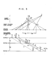
- Fig. 3 shows a case where the third image focusing lens system is added to the first and second image focusing lens systems of Fig. 2.
- the first brightness distribution which is formed on the first logical sensing surface by the first focusing system is spaced apart from the second brightness distribution which is formed on the second logical sensing surface by the second focusing system, by the distance 1, 2 between the first and second focusing systems
- the third brightness distribution which is formed on the third logical sensing surface by the third focusing system is spaced apart from the second brightness distribution by the distance In between the second and third focusing systems.
- the above arrangement of the first, second and third brightness distribution can clearly show a special relation which exists between the geometrical positional relation among bright lines of the same object point which are formed by the focusing systems, and the geometrical positional relations among the focusing systems themselves and between the sensing surface and the focusing systems.
- the special relation is such that a ratio of the distance between the first and second ones of three bright lines of the same object point to the distance between the second and third bright lines is equal to a ratio of the distance between the first and second focusing systems to the distance between the second and third focusing systems.
- the first brightness distribution formed by the first focusing system, the second brightness distribution formed by the second focusing system and the third brightness distribtuion formed by the third focusing system are arranged so that the ratio of the distance between the first brightness distribution and the second brightness distribtuion to the distance between the second brightness distribtuion and the third brightness distribution is equal to the ratio of the distance 1, 2 and the distance 123, three bright lines caused by the same object point lie on a straight line.
- a bright line in the brightness distribution formed by a focusing system for example, the second focusing system
- a bright line in the second brightness distribution is specified, and a bright line is present at each of two positions one of which is spaced apart from the point on the first brightness distribution corresponding to the specified bright line in the leftward direction by a given distance, and the other of which is spaced apart from the point on the third brightness distribution corresponding to the specified bright line in the rightward direction by the distance equal to the product of the given distance and a ratio l 23 /l 12
- the above-mentioned straight line can be obtained by connecting these positions.
- the extraction of the above positions in the first and third brightness distribution capable of satisfying the condition with respect to the ratio l 23 /l 12 and the AND operation for two pieces of brightness information at the above positions can be readily and rapidly performed by hardware or software.
- the remaining straight lines are determined in such a manner that each of bright lines in the second brightness distribution other than the specified bright line is selected, and the presence of a bright line is confirmed at those positions on the first and third brightness distribution which can satisfy the above-mentioned condition with respect to the ratio l 23 /l 12 and another condition that the distance between the selected bright line and the above position on the first brightness distribution is different from the distance between the specified bright line and that position on the first brightness distribution which has a bright line in the preceding processing.
- a vast number of positioning operations are performed on the first, second and third brightness distribution, and the number of positioning operations to be performed is substantially equal to the product of the number of bright lines in the second brightness distribution (that is, the number of object points in a plane which is defined by the focusing systems and bright lines on the actual sensing surface), the number of bright lines in the first or third brightness distribution which are to be combined with the bright lines in the second brightness distribution to determine the distance between the actual sensing surface and each object point in the direction of depth, and the number of bright lines which can be found on the actual sensing surface along a direction corresponding to the change of vertical azimuth angle (that is, a direction parallel to a straight line at which a plane perpendicular to a straight line connecting the first, second and third focusing systems intersects with the actual sensing surface).
- the number of bright lines in each of the first, second and third brightness distribution is equal to the spatial resolving power (namely, resolution).
- the resolution is equal in all directions
- the number of positioning operations is equal to the cube of the resolution at most.
- the number of positioning operation is 125 11 10 6 . If the positioning operations are performed by the serial, digital processing which uses a clock signal of 1 MHz, a processing time proportional to 125 sec will be necessary. If a clock signal of 10 MHz is used, a processing time proportional to 12.5 sec will be required.
- the above positioning operations can be carried out by parallel processing, and thus the processing time can be greatly reduced.
- brightness distribution data corresponding to those straight lines in an actual sensing surface which are parallel to the straight line connecting the first, second and third focusing systems and are equal in number to the resolution can be processed at once by parallel processing. Accordingly, the frequency of processing becomes apparently equal to 10'.
- the serial, digital processing using a clock signal of 1 MHz is carried out, a processing time proportional to 0.25 sec will be necessary. If the clock signal of 10 MHz is used, a processing time proportional to 0.025 sec. will be required.
- the positioning operations for one of the second brightness distribution and the first third brightness distribution can be performed in parallel when a bright line in the other brightness distribution is specified.
- the frequency of processing becomes apparently equal to 500. If the serial, digital processing using the clock signal of 1 MHz is used for the above processing, a processing time proportional to 0.5 msec. will be necessary. If the clock signal of 10 MHz is used, a processing time proportional to 0.05 msec. will be required.
- the pipeline method may be applied to the above 500 processing.
- the number of positioning operations is as small as 125 x 10 3 even when the parallel processing is not used. Accordingly, if the serial, digital processing using the clock signal of 1 MHz is utilized, the processing time will be about 0.125 sec. If the clock signal of 10 MHz is used, the processing time will be about 0.0125 sec.
- the brightness distribution indicating edges in an object system can be used in stead of the brightness distribution indicating object points.
- bright lines in the second brightness distribution which indicate edges are 20% of bright lines in the same brightness distribution which indicate object points
- bright lines in the first or third brightness distribution which indicate edges are 20% of bright lines in the same brightness distribution which indicate objects points
- those bright lines arranged on the actual sensing surface along a direction corresponding to the change of vertical azimuth angle which indicate edges are 20% of bright lines which are arranged along the above direction and indicate object points
- the number of positioning operations is equal to 10 6 . Accordingly, if the serial, digital - processing using the clock signal of 1 MHz is utilized, the processing time will be about 1 sec. If the clock signal of 10 MHz is used, the processing time will be about 0.1 sec.
- the straight lines for extracting candidates for corresponding points can be determined in the above-mentioned processing time.
- the broken lines A, A', B and C correspond to actual object points a, a ', b and c, respectively, but an object point 2 corresponding to the broken line P does not exist actually.
- Fig. 6 shows a case where not only a line segment a c which is an object system, but also first, second and third focusing systems are disposed in the same plane.
- the image of every point in a common area of three triangular regions each bounded by two straight lines connecting one of the first, second and third focusing systems with both ends of the line segment a c and their extensions can be formed on a sensing surface by each of these focusing systems. Accordingly, it seems as if an object system were present throughout the above common area, (namely, hatched area).
- a common portion of three conical regions each bounded by a curved surface connecting one of the first, second and third focusing systems with the periphery of the object system and its extension corresponds to the common area.
- the hatched area of Fig. 6 can be eliminated by placing the third focusing system at a position deviating from the plane, in which the first and second focusing systems and the line segment a c lie, as shown in Fig. 7.
- reference symbol 3' designates the new position of the third focusing system.
- a triangular region bounded by two straight lines connecting the third focusing system with both ends of the line segment a c and their extensions intersects with the above plane only at the line segment a c. Accordingly, the hatched area is extinguished.
- the hatched portion can be made small by additionally disposing the fourth focusing system in the plane which contains the line segment a c and the first, second and third focusing systems, in stead of deviating the third focusing system from the plane.
- the hatched portion can be reduced by changing the geometrical arrangement of the focusing systems or by increasing the number of focusing systems. Further, when the planear shape is converted into a linear shape by preprocessing such as edge extraction, or by decreasing the size of the plate, the portion can be made extremely small.
- the broken line P which appears in Fig. 3 and corresponds to the virtual object point p, can be removed by utilizing the brightness information of bright lines.
- image points of the same object point formed by three focusing systems are equal in brightness to one another, as shown in Fig. 3.
- this straight line is eliminated.
- Bright lines extracted by each of the broken lines A, A', B and C have the same brightness, but two bright lines a1 and a'2 of three bright lines a1, a'2 and b3 extracted by the broken line P are different in bright- nes from the remaining bright line b3. Accordingly, the broken line P is eliminated.
- the processing for eliminating an unwanted straight line can be carried out in a short time by software or hardware. Further, this processing and the above-mentioned positioning processing can be combined so as to be simultaneously performed.
- both the information on the positions of at least two of three bright lines indicated by the corresponding points, on the sensing surface, and the information on the geometrical positional relation between the focusing systems and the sensing surface are used for obtaining two-dimensional distance information of an object point, that is, the distance between the object point and the sensing surface in the direction of depth and one or two horizontal azimuth angles.
- the two-dimensional distance information thus obtained is combined with the vertical azimuth angle information which is obtained independently of the above two-dimensional distance information, to obtain three-dimensional distance information of the object point.
- the processing for obtaining each of the two-dimensional distance information and the three-dimensional distance information is the processing based upon simple algebraic equations, and can be readily performed in a short time.
- the whole quantity of processing necessary for obtaining three-dimensional distance information of an object system is proportional to the number of object points included in the object system.
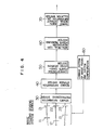
- the first embodiment is carried out by an apparatus which, as shown in Fig. 4, includes image focusing systems 11 to 13 each formed of a lens or mirror, image sensing surfaces 21 to 23, a detected information preprocessing system 30, a detected information storage system 40, a candidate-for-corresponding-point decision system 50, a false-corresponding-point removing system 60, a three-dimensional distance information calculation system 70, and a configuration change system 80 for changing the configuration of the image focusing systems 11 to 13.
- the image focusing systems 11 to 13 are not always required to lie on a straight line parallel to the sensing surfaces 21 to 23, but the positions of the image focusing systems can be changed by the configuration change system 80 so that a plane containing the image focusing systems 11 to 13 makes a desired angle with the image sensing surfaces 21 to 23.
- the images of an object system which are formed on the sensing surfaces 21 to 23 by the focusing systems 11 to 13, are sent to the detected information preprocessing system 30, which corrects errors due to distortions and various aberrations in the focusing system, and extracts bright lines which satisfy a brightness or color condition required for extracting edges or obtaining three-dimensional distance information, if necessary.
- The,. image information thus obtained is sent to the detected information storage system 40.
- the configuration of the focusing systems 11 to 13 and sensing surfaces 21 to 23 is changed by the configuration change system 80, and the image information obtained on the basis of the new configuration is also sent to the detected information storage system 40 through the preprocessing system 30.
- the candidate-for-corresponding-point decision system 50 extracts candidates for corresponding points from a multiplicity of image points stored in the storage system 40, by making use of a special geometrical relation, as mentioned in "SUMMARY OF THE INVENTION".
- the extracted candidates are sent to the false-corresponding-point removing system 60, in which candidates corresponding to a false (namely, now-existing) object point are removed from the extracted candidates by making use of a brightness condition or others, as mentioned in "SUMMARY OF THE INVENTION".
- the remaining candidates are sent to the three-dimensional distance information calculation system 70, to obtain the three-dimensional distance information of the object system in a manner mentioned in "SUMMARY OF THE INVENTION".
- the configuration of the focusing systems 11 to 13 and sensing surfaces 21 to 23 can be freely changed, and moreover, the information obtained on the basis of the new configuration is also stored.
- the apparatus of Fig. 4 can produce the same effect as an apparatus provided with four or more focusing systems, and hence can greatly reduce the redundancy in extracting candidates for corresponding points, no matter what structure the object system may have.
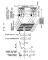
- the second embodiment is carried out by an apparatus which, as shown in Fig. 5, includes color filters 101 to 103 corresponding to three primary , colors, optical path length correction systems 112 and 113, mirrors 123, 133, 121 and 131, a preprocessing system 200, an image focusing system 300, a color image sensor 400, a horizontal addressing system 500, a brightness correcting circuit group 600, a brightness correction system 700, an AND circuit group 800, a two-dimensional distance information calculation system 900, and a three-dimensional distance information calculation system 1000.
- an apparatus which, as shown in Fig. 5, includes color filters 101 to 103 corresponding to three primary , colors, optical path length correction systems 112 and 113, mirrors 123, 133, 121 and 131, a preprocessing system 200, an image focusing system 300, a color image sensor 400, a horizontal addressing system 500, a brightness correcting circuit group 600, a brightness correction system 700, an AND circuit group 800, a two-dimensional distance information calculation system 900, and
- the color filters 101, 102 and 103 transmit red tight, green light and blue light, respectively, and correspond to three primary color filters mounted on the color image sensor 400.
- the color filters 101 to 103, the optical path length correction systems 112 and 113, and the mirrors 123, 133, 121 and 131 are disposed so that the light paths from the color filters 101 to 103 to the color image sensor 400 have the same optical path length, and respective optical axes of three light beams from the color filters 101 to 103 lie in the same horizontal plane and are spaced apart from one another at the light receiving surface of the color image sensor 400 by an amount corresponding to the width - (in a horizontal direction) of each of the color filters mounted on the color image sensor 400.
- each of the mirrors 133 and 131 can transmit light incident upon the back surface thereof.
- the color image sensor 400 is able to be addressed by horizontal direction addressing system 500 in respective colors so that three pixels adjacent to one another and corresponding to three colors in a horizontal direction which are provided with the red, green and blue filters, can be separately addressed by three address lines prepared independently for each color and pixels arranged in a vertical direction and receiving light of the same color can be simultaneously addressed.
- the circuit group 600 includes three correcting circuits for each of pixel layers arranged in a vertical direction.
- the output of each pixel included in the color image sensor 400 is modified in accordance with that circuit constant of each correcting circuit which is specified by the brightness correction system 700, and then three color outputs from three pixels adjacent to one another in a horizontal direction are applied to one of AND circuits included in the AND circuit group 800.
- the brightness correction system 700 gives each correcting circuit of the brightness correcting circuit group 600 a circuit constant necessary for the correction of brightness balance among three primary colors, the brightness correction resulting from the characteristics of the object system, and the classification of brightness into a plurality of levels.
- Three color outputs having been subjected to the brightness correction are applied to one AND circuit of the AND circuit group 800.
- the AND circuit delivers ON-information.
- the AND circuit delivers OFF-information.
- the ON-or OFF-information thus obtained is applied to one two-dimensional distance information calculation circuit of the two-dimensional distance information calculation system 900.
- the second embodiment data from pixel layers arranged in the vertical direction are processed in parallel, and hence the processing time is greatly shortened. Further, the whole processing can be carried out by hardware, and hence not only the productivity and reliability are improved but also the processing speed is increased. Furthermore, only the light receiving surface of a single color image sensor is used as the image sensing surface, and hence the apparatus for carrying out the second embodiment is simple in structure and can be constructed at a low cost.
- a method of forming a three-dimensional stereo vision is provided in which the processing time is short, and the fundamental error dependent upon the spatial distribution of object points can be avoided.
- the image of an object system is formed by an optical system.
- the present invention is not limited to the optical system, but is applicable to various propagation systems such as electromagnetic wave systems other than the optical system, an accoustic system, an elastic wave system, and a particle beam system (for example, the electron beam of an electron microscope).
Landscapes
- Engineering & Computer Science (AREA)
- Multimedia (AREA)
- Signal Processing (AREA)
- Image Processing (AREA)
- Measurement Of Optical Distance (AREA)
- Length Measuring Devices By Optical Means (AREA)
- Image Generation (AREA)
- Image Analysis (AREA)
- Image Input (AREA)
- Stereoscopic And Panoramic Photography (AREA)
- Testing, Inspecting, Measuring Of Stereoscopic Televisions And Televisions (AREA)
Applications Claiming Priority (2)
| Application Number | Priority Date | Filing Date | Title |
|---|---|---|---|
| JP60080159A JPH07109625B2 (ja) | 1985-04-17 | 1985-04-17 | 三次元立体視方法 |
| JP80159/85 | 1985-04-17 |
Publications (4)
| Publication Number | Publication Date |
|---|---|
| EP0199269A2 true EP0199269A2 (de) | 1986-10-29 |
| EP0199269A3 EP0199269A3 (en) | 1988-07-20 |
| EP0199269B1 EP0199269B1 (de) | 1992-01-22 |
| EP0199269B2 EP0199269B2 (de) | 1996-03-13 |
Family
ID=13710522
Family Applications (1)
| Application Number | Title | Priority Date | Filing Date |
|---|---|---|---|
| EP86105212A Expired - Lifetime EP0199269B2 (de) | 1985-04-17 | 1986-04-15 | Verfahren zur Gewinnung von dreidimensionalen Entfernungsdaten |
Country Status (6)
| Country | Link |
|---|---|
| US (1) | US4792694A (de) |
| EP (1) | EP0199269B2 (de) |
| JP (1) | JPH07109625B2 (de) |
| KR (1) | KR950001578B1 (de) |
| CA (1) | CA1255788A (de) |
| DE (1) | DE3683524D1 (de) |
Families Citing this family (16)
| Publication number | Priority date | Publication date | Assignee | Title |
|---|---|---|---|---|
| JP2681941B2 (ja) * | 1987-09-14 | 1997-11-26 | ソニー株式会社 | 画像処理装置 |
| JPS6473468A (en) * | 1987-09-14 | 1989-03-17 | Sony Corp | Image processor |
| US4965840A (en) * | 1987-11-27 | 1990-10-23 | State University Of New York | Method and apparatus for determining the distances between surface-patches of a three-dimensional spatial scene and a camera system |
| US5193124A (en) * | 1989-06-29 | 1993-03-09 | The Research Foundation Of State University Of New York | Computational methods and electronic camera apparatus for determining distance of objects, rapid autofocusing, and obtaining improved focus images |
| US5231443A (en) * | 1991-12-16 | 1993-07-27 | The Research Foundation Of State University Of New York | Automatic ranging and automatic focusing |
| IL115971A (en) * | 1995-11-14 | 1997-01-10 | Razon Moshe | Computer stereo vision system and method |
| JP3852070B2 (ja) * | 1999-11-11 | 2006-11-29 | 富士通株式会社 | 光路シミュレーションcad装置及び方法 |
| US7170677B1 (en) | 2002-01-25 | 2007-01-30 | Everest Vit | Stereo-measurement borescope with 3-D viewing |
| US7027081B2 (en) * | 2003-12-21 | 2006-04-11 | Kremen Stanley H | System and apparatus for recording, transmitting, and projecting digital three-dimensional images |
| JP2007124088A (ja) * | 2005-10-26 | 2007-05-17 | Olympus Corp | 画像撮影装置 |
| US20080298674A1 (en) * | 2007-05-29 | 2008-12-04 | Image Masters Inc. | Stereoscopic Panoramic imaging system |
| US9068831B2 (en) * | 2011-05-27 | 2015-06-30 | Panasonic Intellectual Property Management Co., Ltd. | Image processing apparatus and image processing method |
| US9185391B1 (en) | 2014-06-17 | 2015-11-10 | Actality, Inc. | Adjustable parallax distance, wide field of view, stereoscopic imaging system |
| JP6084192B2 (ja) * | 2014-10-15 | 2017-02-22 | 本田技研工業株式会社 | 物体認識装置 |
| CN114979509A (zh) * | 2017-11-29 | 2022-08-30 | 超威半导体公司 | 计算传感器 |
| FR3080937B1 (fr) | 2018-05-03 | 2021-06-04 | Commissariat Energie Atomique | Procede et dispositif de reconnaissance de distance en temps reel |
Family Cites Families (11)
| Publication number | Priority date | Publication date | Assignee | Title |
|---|---|---|---|---|
| US3770887A (en) * | 1972-01-31 | 1973-11-06 | Us Navy | Color stereo television |
| JPS51142212A (en) * | 1975-06-02 | 1976-12-07 | Hokkaido Daigaku | Tridimensional television system |
| JPS52119818A (en) * | 1976-04-01 | 1977-10-07 | Kiyoshi Nagata | Stereoscopic color televisition transmitter*receiver system and apparatus therefor |
| US4142138A (en) * | 1977-05-02 | 1979-02-27 | E. I. Du Pont De Nemours And Company | Motor control |
| DE2734069A1 (de) * | 1977-07-28 | 1979-02-01 | Univ Moskovsk | Stereoskopisches farbfernsehverfahren |
| US4217602A (en) * | 1979-02-12 | 1980-08-12 | Lady Bea Enterprises, Inc. | Method and apparatus for generating and processing television signals for viewing in three dimensions |
| US4259589A (en) * | 1979-07-20 | 1981-03-31 | Solid Photography, Inc. | Generation of contiguous data files of three-dimensional information |
| FR2498402A1 (fr) * | 1981-01-16 | 1982-07-23 | Centre Nat Rech Scient | Procede et dispositif de visualisation tri-dimensionnelle a partir de video-signaux, notamment pour microscopie electronique |
| NL8202934A (nl) * | 1982-07-21 | 1984-02-16 | Philips Nv | Inrichting voor het weergeven van drie-dimensionale beelden. |
| US4654872A (en) * | 1983-07-25 | 1987-03-31 | Omron Tateisi Electronics Co. | System for recognizing three-dimensional objects |
| JPS6054081A (ja) * | 1983-09-03 | 1985-03-28 | Omron Tateisi Electronics Co | 両眼視系画像の特徴点認識装置 |
-
1985
- 1985-04-17 JP JP60080159A patent/JPH07109625B2/ja not_active Expired - Lifetime
-
1986
- 1986-04-15 EP EP86105212A patent/EP0199269B2/de not_active Expired - Lifetime
- 1986-04-15 CA CA000506640A patent/CA1255788A/en not_active Expired
- 1986-04-15 DE DE8686105212T patent/DE3683524D1/de not_active Expired - Lifetime
- 1986-04-16 KR KR1019860002914A patent/KR950001578B1/ko not_active Expired - Fee Related
- 1986-04-17 US US06/853,231 patent/US4792694A/en not_active Expired - Lifetime
Also Published As
| Publication number | Publication date |
|---|---|
| EP0199269B2 (de) | 1996-03-13 |
| CA1255788A (en) | 1989-06-13 |
| EP0199269B1 (de) | 1992-01-22 |
| KR860008462A (ko) | 1986-11-15 |
| JPS61240376A (ja) | 1986-10-25 |
| JPH07109625B2 (ja) | 1995-11-22 |
| EP0199269A3 (en) | 1988-07-20 |
| DE3683524D1 (de) | 1992-03-05 |
| KR950001578B1 (ko) | 1995-02-25 |
| US4792694A (en) | 1988-12-20 |
Similar Documents
| Publication | Publication Date | Title |
|---|---|---|
| EP0199269B1 (de) | Verfahren zur Gewinnung von dreidimensionalen Entfernungsdaten | |
| CA2101996C (en) | Validation of optical ranging of a target surface in a cluttered environment | |
| US5349378A (en) | Context independent fusion of range and intensity imagery | |
| US4893183A (en) | Robotic vision system | |
| EP0523152B1 (de) | Dreidimensionales echtzeit-sensorsystem | |
| EP2568253B1 (de) | Verfahren und system zur messung von strukturiertem licht | |
| CA1319188C (en) | Three dimensional imaging device | |
| US20040125228A1 (en) | Apparatus and method for determining the range of remote objects | |
| GB2297008A (en) | Visual recognition system for ladar sensors | |
| CN112802114B (zh) | 多视觉传感器融合装置及其方法和电子设备 | |
| CN114742898B (zh) | 一种激光雷达和相机的联合标定方法及系统 | |
| JP4448233B2 (ja) | 着陸地点探索装置、それを用いた飛行体、および着陸地点評価装置 | |
| US5703677A (en) | Single lens range imaging method and apparatus | |
| US6980210B1 (en) | 3D stereo real-time sensor system, method and computer program therefor | |
| JPH05108820A (ja) | 最小差プロセツサ | |
| RU2363018C1 (ru) | Способ селекции объектов на удаленном фоне | |
| EP0069937A1 (de) | Mittels "Mica" verstärkte Polyolefin-Zusammensetzungen | |
| Xie et al. | Active and intelligent sensing of road obstacles: Application to the European Eureka-PROMETHEUS project | |
| Hobrough et al. | Stereopsis for robots by iterative stereo image matching | |
| US4958077A (en) | Method and apparatus for displaying moving objects | |
| GB2272285A (en) | Determining the position of edges and corners in images. | |
| CN113239948B (zh) | 一种面向毫米波雷达与视频图像的数据融合方法及系统 | |
| CN118115347A (zh) | 信息处理装置、点云数据的处理方法及信息处理方法 | |
| RU2519005C1 (ru) | Способ допускового контроля печатных плат | |
| US5023724A (en) | Focus enhancing method |
Legal Events
| Date | Code | Title | Description |
|---|---|---|---|
| PUAI | Public reference made under article 153(3) epc to a published international application that has entered the european phase |
Free format text: ORIGINAL CODE: 0009012 |
|
| AK | Designated contracting states |
Kind code of ref document: A2 Designated state(s): DE FR GB IT |
|
| PUAL | Search report despatched |
Free format text: ORIGINAL CODE: 0009013 |
|
| AK | Designated contracting states |
Kind code of ref document: A3 Designated state(s): DE FR GB IT |
|
| 17P | Request for examination filed |
Effective date: 19881223 |
|
| 17Q | First examination report despatched |
Effective date: 19910212 |
|
| GRAA | (expected) grant |
Free format text: ORIGINAL CODE: 0009210 |
|
| AK | Designated contracting states |
Kind code of ref document: B1 Designated state(s): DE FR GB IT |
|
| REF | Corresponds to: |
Ref document number: 3683524 Country of ref document: DE Date of ref document: 19920305 |
|
| ET | Fr: translation filed | ||
| ITF | It: translation for a ep patent filed | ||
| PLBI | Opposition filed |
Free format text: ORIGINAL CODE: 0009260 |
|
| 26 | Opposition filed |
Opponent name: FIRMA CARL ZEISS Effective date: 19921020 |
|
| PUAH | Patent maintained in amended form |
Free format text: ORIGINAL CODE: 0009272 |
|
| STAA | Information on the status of an ep patent application or granted ep patent |
Free format text: STATUS: PATENT MAINTAINED AS AMENDED |
|
| 27A | Patent maintained in amended form |
Effective date: 19960313 |
|
| AK | Designated contracting states |
Kind code of ref document: B2 Designated state(s): DE FR GB IT |
|
| ET3 | Fr: translation filed ** decision concerning opposition | ||
| ITF | It: translation for a ep patent filed | ||
| REG | Reference to a national code |
Ref country code: GB Ref legal event code: IF02 |
|
| PGFP | Annual fee paid to national office [announced via postgrant information from national office to epo] |
Ref country code: FR Payment date: 20050322 Year of fee payment: 20 |
|
| PGFP | Annual fee paid to national office [announced via postgrant information from national office to epo] |
Ref country code: GB Payment date: 20050324 Year of fee payment: 20 |
|
| PGFP | Annual fee paid to national office [announced via postgrant information from national office to epo] |
Ref country code: IT Payment date: 20050421 Year of fee payment: 20 |
|
| PGFP | Annual fee paid to national office [announced via postgrant information from national office to epo] |
Ref country code: DE Payment date: 20050609 Year of fee payment: 20 |
|
| PG25 | Lapsed in a contracting state [announced via postgrant information from national office to epo] |
Ref country code: GB Free format text: LAPSE BECAUSE OF EXPIRATION OF PROTECTION Effective date: 20060414 |
|
| REG | Reference to a national code |
Ref country code: GB Ref legal event code: PE20 |