EP0199080B1 - Cassette for storing elongated objects - Google Patents
Cassette for storing elongated objects Download PDFInfo
- Publication number
- EP0199080B1 EP0199080B1 EP86103639A EP86103639A EP0199080B1 EP 0199080 B1 EP0199080 B1 EP 0199080B1 EP 86103639 A EP86103639 A EP 86103639A EP 86103639 A EP86103639 A EP 86103639A EP 0199080 B1 EP0199080 B1 EP 0199080B1
- Authority
- EP
- European Patent Office
- Prior art keywords
- insert
- lid
- pivotable
- swivel
- container
- Prior art date
- Legal status (The legal status is an assumption and is not a legal conclusion. Google has not performed a legal analysis and makes no representation as to the accuracy of the status listed.)
- Expired - Lifetime
Links
- 238000004519 manufacturing process Methods 0.000 description 2
- 230000005484 gravity Effects 0.000 description 1
- 238000000034 method Methods 0.000 description 1
Images
Classifications
-
- B—PERFORMING OPERATIONS; TRANSPORTING
- B25—HAND TOOLS; PORTABLE POWER-DRIVEN TOOLS; MANIPULATORS
- B25H—WORKSHOP EQUIPMENT, e.g. FOR MARKING-OUT WORK; STORAGE MEANS FOR WORKSHOPS
- B25H3/00—Storage means or arrangements for workshops facilitating access to, or handling of, work tools or instruments
- B25H3/003—Holders for drill bits or the like
Definitions
- the object of the present invention is therefore to propose a generic cassette that is cheaper to manufacture and offers better use of space.
- connection member passes from the cover to the swivel insert remote from the cover and thereby passes through all further swivel inserts.
- the cover Due to the direct connection of the cover with the first swivel insert not adjacent to it, the other connecting elements are completely eliminated. If the cover is swung up, it pulls by means of the connecting link the first swivel insert also with high. The second swivel insert lying between the cover and the first swivel insert is carried along by the first swivel insert. When the cassette is closed, the cover pivots the first pivot element into the container by means of the connecting member and pushes the second pivot element itself.
- two pivoting inserts are arranged so as to be pivotable about a common pivoting axis and have support members in their lower region which abut one another and cause the pivoting inserts to take one another when pivoting up and down.
- a link is movably attached to the lid and to the immediately adjacent swivel insert.
- both swivel inserts on a common swivel axis also has the disadvantage that the elongated objects to be stored in the swivel inserts are no longer directly above the swivel axis when the cassette is open.
- an object for example a larger twist drill
- the torque balance around the pivot axis changes accordingly.
- the lid and the pivoting inserts themselves must be made relatively heavy, which means that they can tip over to prevent the entire cassette, also requires a correspondingly heavy training of the container itself.
- the connecting member preferably extends from the pivot insert remote from the cover through openings in the second pivot insert to the cover. This makes it possible to use the full width of the container in the swivel axis direction for both swivel inserts.
- At least one of the swivel inserts has two parallel rows of storage spaces. This reduces the use of equipment and materials.
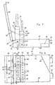
- a cuboid-shaped container 10 has two parallel longitudinal walls 11, 12, two transverse walls 13, 14 perpendicular to it and a bottom 15. Inside the container 10 there is an oblique to the other walls in a corner formed by the longitudinal wall 12 and the transverse wall 13 Oblique wall 16 standing vertically on the floor 15. Two handles 17, 18 are fastened to the transverse wall 12.
- a rectangular cover 20 is articulated on the upper edge of the transverse wall 14. It can be pivoted about a pivot axis 21 which runs adjacent to the upper edge of the transverse wall 14 and is defined by two joints 22, 23. At the end of the cover 20 facing away from the pivot axis 21, a handle 24 is arranged.
- a first pivot insert 30 is located in the vicinity of the transverse wall 14. It can be pivoted about a pivot axis 31 parallel to the pivot axis 21 of the cover 20.
- the pivot axis 31 passes through the longitudinal walls 11 and 12 of the container 10 and can be defined, for example, by rivets.
- the swivel insert 30 is largely cuboid; its extension in the direction of the swivel axis is somewhat less than the length of the transverse walls 13, 14.
- the swivel axis 31 is close to a side of the swivel insert 30 that is rounded in the exemplary embodiment shown in FIGS. 1 and 2.
- the side of the swivel side remote from this rounded side of the Swivel insert 30 is formed by two parallel perforated webs 32, 33 with aligned holes.
- the holes delimit cylindrical storage spaces 34 for elongated objects G.
- the contact surfaces 35 do not extend over the entire width of the swivel insert 30, but instead are each limited to the width of one or more storage spaces 34. They close off individual storage spaces 34 on the side opposite the perforated webs 33.
- a second swivel insert 40 is arranged between the first swivel insert 30 and the transverse wall 14 of the container 10. It can be pivoted about a pivot axis 41 parallel to the pivot axes 21 and 31, which, like the pivot axis 31, passes through the longitudinal walls 11, 12, but closer to its upper edge than the pivot axis 31.
- the second pivot insert 40 is configured similarly to the first pivot insert 30. It has on the side remote from the axis two parallel perforated webs 42, 43 with holes that delimit cylindrical storage spaces 44, and in the area near the axis, contact surfaces 45 parallel to it the perforated webs 42, 43.
- the walls of the second pivot insert 40 which are parallel to the pivot axis 41 and perpendicular to the perforated webs 42, 43 have openings 46 in the central region (indicated schematically in FIG. 2).
- the longitudinal walls 11, 12 have lugs 19 bent into the container 10 at the same distance from the transverse wall 14 above the pivot axis 41 and between the pivot axis 41 and the transverse wall 14.
- the lugs 19 lie on the wall of the cross wall 14 facing Swivel insert 40 on.
- a connecting member 50 connects the cover 20 to the first pivot insert 30.
- the connecting member 50 consists of a U-shaped wire piece, the legs of which extend parallel through the opening 46 in the second pivot insert 40 perpendicular to the pivot axis 41, run out as hooks 51 and in eyelets are hooked in the area away from the axis on the side of the first swivel insert 30 facing the cover 20.
- the base of the connecting member 50 connecting the two legs of the wire piece is guided through a notch 25 in the cover 20.
- the two legs each lead exactly through spaces between two storage spaces 44 through the second swivel insert 40. They enclose one of the storage spaces 44 between them.
- objects G are inserted through the holes in the perforated webs 32, 33 and 42, 43 into the storage spaces 34, 44 in the swivel inserts 30, 40 when the cassette is open.
- the elongated objects G in the illustration twist drills, stand with their lower ends on the contact surfaces 35 and 45.
- the lid 20 is closed by means of the handle 24, i.e. pivoted about the pivot axis 21 (to the right in Fig. 1).
- the connecting member 50 thereby pivots the first pivot insert 30 in the same direction of rotation and the pivot axis 31.
- the second pivot insert 40 initially remains stationary until the inside of the cover 20 abuts against its upper edge or against the objects G inserted into it.
- a further pivoting of the lid 20 also takes the second pivoting insert 40 with it and pivots it about the pivoting axis 41.
- the two pivoting inserts 30, 40 lie one above the other in the container 10.
- the inclined wall 16 prevents shorter, If the cassette is shaken, objects G to be inserted into storage spaces 34, 44 adjacent to side wall 12 slide out of swivel inserts 30, 40.
- the connecting member 50 pulls the first swivel insert 30 with it while the cover 20 is folded up about the swivel axis 21. The latter swivels about the swivel axis 31.
- the second swivel insert 40 lying above the first swivel insert 30 is taken along and swiveled about its swivel axis 41. This process continues until the second swivel insert 40 bumps against the lugs 19 on the longitudinal walls 11, 12. This happens when both swivel inserts 30, 40 and the objects G inserted into them are vertical. At this moment, the cover 20 is already somewhat beyond its vertical position, the opening angle of the cassette is approximately 100 °.
- the connector 50 holds the lid 20 and prevents it from opening further.
- the cover 20 pulls on the first swivel insert 30 by means of the connecting member 50.
- the weight of the cover 20 thus prevents the swivel inserts 30, 40 from tipping over unintentionally and the cassette closing itself.
- the objects G are now available for use and can be removed from the swivel inserts 30.40. Since they are essentially exactly above the pivot axes 31, 41, no change in the torque balance occurs when the objects G are removed or inserted.
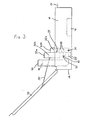
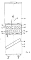
- FIGS. 3 and 4 largely corresponds to the first, described above.
- the main differences are in the design of the swivel inserts 30 and 40.
- the first swivel insert 30 remote from the cover has four parallel perforated webs 32a, 32b, 33a, 33b on its side remote from the axis, two of which are arranged one above the other and have aligned holes. As a result, two parallel rows of holes are formed, which accordingly delimit two parallel rows of cylindrical storage spaces 34 for the elongated objects G.
- Each of the two rows of storage rooms 34 contact areas 35 are assigned.
- An intermediate wall 37 is provided here between the two rows perpendicular to the contact surfaces 35.
- the second swivel insert 40 is each adjacent to a projection 47 and provided parallel to the longitudinal walls 11 and 12.
- the pivot axis 41 runs through these projections 47.
- the operation when opening and closing the cassette corresponds to that of the first embodiment.
- the objects G are not all above the pivot axes 31, 41 in the open position.
Landscapes
- Engineering & Computer Science (AREA)
- Mechanical Engineering (AREA)
- Details Of Rigid Or Semi-Rigid Containers (AREA)
- Purses, Travelling Bags, Baskets, Or Suitcases (AREA)
- Packaging Of Annular Or Rod-Shaped Articles, Wearing Apparel, Cassettes, Or The Like (AREA)
Description
Die Erfindung betrifft eine Kassette zur Aufbewahrung länglicher Gegenstände, insbesondere von Werkzeugen wie Spiralbohrern o. dgl.,
- a) mit einem quaderförmigen Behälter,
- b) mit einem hochschwenkbaren Deckel für den Behälter,
- c) mit einem deckelfernen ersten Schwenkeinsatz in dem Behälter zur Aufnahme der Gegenstände, der um eine zur Schwenkachse des Deckels parallele und durch den Behälter verlaufende Schwenkachse schwenkbar gelagert und beim Öffnen des Deckels selbsstätig hochschwenkbar ist,
- d) mit mindestens einem zweiten Schwenkeinsatz zur Aufnahme der Gegenstände, der zwischen dem Deckel und dem ersten Schwenkeinsatz im Schwenkbereich beider angeordnet und um eine zur Schwenkachse des Deckels parallele und durch den Behälter verlaufende Schwenkachse schwenkbar gelagert ist und
- e) mit mindestens einem Verbindungsglied zwischen Schwenkeinsätzen und Deckel.
- a) with a rectangular container,
- b) with a hinged lid for the container,
- c) with a first pivoting insert remote from the lid in the container for receiving the objects, which is pivotably mounted about a pivoting axis parallel to the pivoting axis of the lid and extending through the container and can be pivoted up automatically when the lid is opened,
- d) with at least one second swivel insert for receiving the objects, which is arranged between the cover and the first swivel insert in the swivel range of both and is pivotably mounted about a swivel axis parallel to the swivel axis of the cover and extending through the container, and
- e) with at least one connecting link between swivel inserts and cover.
In der US-A- 30 74 539 wird eine derartige Kassette beschrieben. Der dem Deckel unmittelbar benachbarte Schwenkeinsatz ist mittels beweglicher Verbindungsglieder mit dem Deckel selbst verbunden. Zwei andere, hiervon unabhängige Verbindungselemente verbinden die Schwenkeinsätze miteinander. Diese Verbindungselemente sind gelenkig an zu den Schwenkachsen senkrecht stehenden Flächen der Schwenkeinsätze befestigt. Nachteilig an dieser bekannten Kassette ist der komplizierte Aufwand für die zusätzlichen Verbindungselemente, die die Kassette verteuern und darüber hinaus auch Platz kosten.Such a cassette is described in US-A-30 74 539. The swivel insert immediately adjacent to the cover is connected to the cover itself by means of movable connecting members. Two other connecting elements, which are independent of this, connect the swivel inserts to one another. These connecting elements are articulated to surfaces of the swivel inserts which are perpendicular to the swivel axes. A disadvantage of this known cassette is the complicated outlay for the additional connecting elements, which make the cassette more expensive and also cost space.
Aufgabe der vorliegenden Erfindung ist es daher, eine gattungsgemäße Kassette vorzuschlagen, die kostengünstiger herzustellen ist und eine bessere Platzausnutzung bietet.The object of the present invention is therefore to propose a generic cassette that is cheaper to manufacture and offers better use of space.
Diese Aufgabe wird dadurch gelöst, daß das Verbindungsglied vom Deckel zum deckelfernen Schwenkeinsatz durchgeht und dabei alle weiteren Schwenkeinsätze passiert.This object is achieved in that the connecting member passes from the cover to the swivel insert remote from the cover and thereby passes through all further swivel inserts.
Durch die direkte Verbindung des Deckels mit dem ihm nicht benachbarten ersten Schwenkeinsatz entfallen die anderen Verbindungselemente vollständig. Wird der Deckel hochgeschwenkt, so zieht er mittels des Verbindungsgliedes den ersten Schwenkeinsatz ebenfalls mit hoch. Der zwischen dem Deckel und dem ersten Schwenkeinsatz liegende zweite Schwenkeinsatz wird dabei vom ersten Schwenkeinsatz mitgenommen. Beim Verschließen der Kassette schwenkt der Deckel mittels des Verbindungsgliedes das erste Schwenkelement in den Behälter und schiebt selbst das zweite Schwenkelement nach.Due to the direct connection of the cover with the first swivel insert not adjacent to it, the other connecting elements are completely eliminated. If the cover is swung up, it pulls by means of the connecting link the first swivel insert also with high. The second swivel insert lying between the cover and the first swivel insert is carried along by the first swivel insert. When the cassette is closed, the cover pivots the first pivot element into the container by means of the connecting member and pushes the second pivot element itself.
In einer anderen, aus der DE-C- 24 61 766 bekannten Kassette sind zwei Schwenkeinsätze um eine gemeinsame Schwenkachse verschwenkbar angeordnet und besitzen in ihrem unteren Bereich Abstützglieder, die aneinander anliegen und bewirken, daß beim Hochschwenken und beim Absenken die Schwenkeinsätze einander mitnehmen. Ein Verbindungsglied ist beweglich am Deckel und am unmittelbar benachbarten Schwenkeinsatz befestigt. Nachteilig an einer derartigen Kassette ist, daß zusätzliche Elemente an den Schwenkeinsätzen erforderlich sind, um sie auf einer gemeinsamen Schwenkachse lagern zu können. Außerdem muß die Erstreckung in Schwenkachsrichtung der beiden Schwenkeinsätze unterschiedlich sein, was zum einen die Herstellung verkompliziert und zum anderen Platz kostet.In another cassette known from DE-C-24 61 766, two pivoting inserts are arranged so as to be pivotable about a common pivoting axis and have support members in their lower region which abut one another and cause the pivoting inserts to take one another when pivoting up and down. A link is movably attached to the lid and to the immediately adjacent swivel insert. A disadvantage of such a cassette is that additional elements are required on the swivel inserts in order to be able to store them on a common swivel axis. In addition, the extent in the swivel axis direction of the two swivel inserts must be different, which on the one hand complicates the manufacture and on the other hand costs space.
Die Lagerung beider Schwenkeinsätze auf einer gemeinsamen Schwenkachse hat darüber hinaus den Nachteil, daß die in de Schwenkeinsätzen aufzubewahrenden länglichen Gegenstände bei einer geöffneten Kassette nicht mehr unmittelbar über der Schwenkachse stehen. Beim Entnehmen oder Einstecken eines Gegenstand, beispielsweise eines größeren Spiralbohrers, ändert sich dementsprechend die Drehmomentbilanz um die Schwenkachse. Um ein unbeabsichtigtes Zuklappen der Kassette zu verhindern, müssen entsprechend der Deckel und die Schwenkeinsätze selbst relativ schwer ausgebildet werden, was, um ein Umkippen der gesamten Kassette zu verhindern, auch eine entsprechend schwere Ausbildung des Behälters selbst erfordert.The storage of both swivel inserts on a common swivel axis also has the disadvantage that the elongated objects to be stored in the swivel inserts are no longer directly above the swivel axis when the cassette is open. When removing or inserting an object, for example a larger twist drill, the torque balance around the pivot axis changes accordingly. In order to prevent the cassette from being inadvertently closed, the lid and the pivoting inserts themselves must be made relatively heavy, which means that they can tip over to prevent the entire cassette, also requires a correspondingly heavy training of the container itself.
Diese Probleme treten in einer bevorzugten Ausführungsform der Erfindung nicht auf. Sie zeichnet sich dadurch aus, daß die Seitenwände des Behälters Nasen aufweisen, die bei aufrechtstehendem zweiten Schwenkeinsatz an der dem Deckel zugewandten Seite des zweiten Schwenkeinsatzes anliegen. Sie verhindern auf diese Weise, daß die beiden Schwenkeinsätze über die aufrechtstehende Position hinausgeschwenkt werden können. Eingesteckte Gegenstände liegen damit mit ihrem Schwerpunkt genau über der ihnen zugeordneten Schwenkachse und beeinflussen die Drehmomentbilanz nicht. Ein unbeabsichtigtes Zuklappen der Kassette beim Herausnehmen oder Einstecken schwerer Gegenstände ist damit vermieden, ohne daß besonders schwere Materialien zum Bau der Kassette verwendet werden müssen.These problems do not occur in a preferred embodiment of the invention. It is characterized in that the side walls of the container have lugs which, when the second pivoting insert is upright, bear against the side of the second pivoting insert facing the cover. In this way you prevent the two pivoting inserts from being pivoted beyond the upright position. With their center of gravity, inserted objects lie exactly above the swivel axis assigned to them and do not influence the torque balance. An unintentional collapse of the cassette when removing or inserting heavy objects is avoided without having to use particularly heavy materials to build the cassette.
Das Verbindungsglied erstreckt sich vorzugsweise vom deckelfernen Schwenkeinsatz durch Öffnungen im zweiten Schwenkeinsatz zum Deckel. Dadurch wird es möglich, für beide Schwenkeinsätze die volle Breite des Behälters in Schwenkachsrichtung auszunutzen.The connecting member preferably extends from the pivot insert remote from the cover through openings in the second pivot insert to the cover. This makes it possible to use the full width of the container in the swivel axis direction for both swivel inserts.
In einer Ausführungsform, die für die Aufnahme einer größeren Zahl länglicher Gegenstände geeignet ist, weist mindestens einer der Schwenkeinsätze zwei parallele Reihen Aufbewahrungsräume auf. Dies verringert den apparativen und den Materialeinsatz.In one embodiment, which is suitable for accommodating a large number of elongated objects, at least one of the swivel inserts has two parallel rows of storage spaces. This reduces the use of equipment and materials.
Weitere bevorzugte Merkmale der Erfindung sind in den Unteransprüchen gekennzeichnet.Further preferred features of the invention are characterized in the subclaims.
Im folgenden werden anhand der Zeichnungen zwei Ausführungsbeispiele der Erfindung im einzelnen beschrieben. Es zeigt:
- Fig. 1
- eine Seitenansicht einer geöffneten Kassette;
- Fig. 2
- eine Draufsicht auf die geöffnete Kassette aus Fig. 1;
- Fig. 3
- eine Seitenansicht einer geöffneten Kassette gemäß einer anderen Ausführungsform;
- Fig. 4
- eine Draufsicht auf die geöffnete Kassette aus Fig. 3.
- Fig. 1
- a side view of an opened cassette;
- Fig. 2
- a plan view of the opened cassette of Fig. 1;
- Fig. 3
- a side view of an opened cassette according to another embodiment;
- Fig. 4
- 3 shows a top view of the opened cassette from FIG. 3.
Ein quaderförmiger Behälter 10 besitzt zwei parallele Längswände 11, 12, zwei senkrecht dazu stehende Querwände 13, 14 und einen Boden 15. Im Inneren des Behälters 10 befindet sich schräg zu den anderen Wänden in einer von der Längswand 12 und der Querwand 13 gebildeten Ecke eine senkrecht auf dem Boden 15 stehende Schrägwand 16. An der Querwand 12 sind zwei Griffe 17, 18 befestigt.A cuboid-
An der Oberkante der Querwand 14 ist ein rechteckiger Deckel 20 angelenkt. Er ist um eine Schwenkachse 21 schwenkbar, die benachbart zu Oberkante der Querwand 14 verläuft und durch zwei Gelenke 22, 23 definiert wird. An dem der Schwenkachse 21 abgewandten Ende des Deckels 20 ist ein Griff 24 angeordnet.A
In der Nähe der Querwand 14 befindet sich eine erster Schwenkeinsatz 30. Er ist um eine zur Schwenkachse 21 des Deckels 20 parallele Schwenkachse 31 schwenkbar.A
Die Schwenkachse 31 geht durch die Längswände 11 und 12 des Behälters 10 und kann beispielsweise durch Nieten definiert werden. Der Schwenkeinsatz 30 ist weitgehend quaderförmig; seine Erstreckung in Richtung der Schwenkachse ist dabei etwas geringer als die Länge der Querwände 13, 14. Die Schwenkachse 31 liegt nahe einer in dem in Fig. 1 und 2 dargestellten Ausführungsbeispiel abgerundeten Seite des Schwenkeinsatzes 30. Die achsferne, dieser abgerundeten Seite gegenüberliegende Seite des Schwenkeinsatzes 30 wird durch zwei parallele gelochte Stege 32, 33 mit aufeinander ausgerichteten Löchern gebildet. Die Löcher begrenzen zylindrische Aufbewahrungsräume 34 für längliche Gegenstände G. Im Inneren des Schwenkeinsatzes 30 befinden sich parallele Aufstandsflächen 35 ohne Löcher in verschiedenen Abständen von den gelochten Stegen 32, 33. Die Aufstandsflächen 35 gehen jeweils nicht über die gesamte Breite des Schwenkeinsatzes 30 durch, sondern sind jeweils auf die Breite von einem oder mehreren Aufbewahrungsräumen 34 beschränkt. Sie schließen einzelne Aufbewahrungsräume 34 auf der den gelochten Stege 33 entgegengesetzten Seite ab.The
Zwischen dem ersten Schwenkeinsatz 30 und der Querwand 14 des Behälters 10 ist ein zweiter Schwenkeinsatz 40 angeordnet. Er ist um eine zu den Schwenkachsen 21 und 31 parallele Schwenkachse 41 schwenkbar, die wie die Schwenkachse 31 durch die Längswände 11, 12 geht, aber näher an deren Oberkante als die Schwenkachse 31. Der zweite Schwenkeinsatz 40 ist ähnlich dem ersten Schwenkeinsatz 30 ausgebildet. Er besitzt auf der achsfernen Seite zwei parallele gelochte Stege 42, 43 mit Löchern, die zylindrische Aufbewahrungsräume 44 begrenzen, und im achsnahen Bereich Aufstandsflächen 45 parallel zu den gelochten Stegen 42, 43. Die zu der Schwenkachse 41 parallelen und zu den gelochten Stegen 42, 43 senkrechten Wände des zweiten Schwenkeinsatzes 40 weisen im mittleren Bereich Öffnungen 46 auf (in Fig. 2 schematisch angedeutet).A second swivel insert 40 is arranged between the
Die Längswände 11,12 besitzen im gleichen Abstand von der Querwand 14 oberhalb der Schwenkachse 41 und zwischen Schwenkachse 41 und Querwand 14 in den Behälter 10 hinein gebogene Nasen 19. Bei aufrecht stehendem Schwenkeinsatz 40 liegen die Nasen 19 an der der Querwand 14 zugewandten Wand des Schwenkeinsatzes 40 an.The
Ein Verbindungsglied 50 verbindet den Deckel 20 mit dem ersten Schwenkeinsatz 30. Das Verbindungsglied 50 besteht aus einem U-förmig gebogenen Drahtstück, dessen Schenkel sich parallel durch die Öffnung 46 im zweiten Schwenkeinsatz 40 senkrecht zur Schwenkachse 41 erstrecken, als Haken 51 auslaufen und in Ösen im achsfernen Bereich auf der dem Deckel 20 zugewandten Seite des ersten Schwenkeinsatzes 30 eingehakt sind. Die die beiden Schenkel des Drahtstücks verbindende Basis des Verbindungsglieds 50 ist durch eine Einkerbung 25 im Deckel 20 geführt. Die beiden Schenkel führen jeweils genau durch Zwischenräume zwischen zwei Aufbewahrungsräumen 44 durch den zweiten Schwenkeinsatz 40. Sie schließen zwischen sich einen der Aufbewahrungsräume 44 ein.A connecting
Zur Benutzung der Kassette werden bei geöffneter Kassette Gegenstände G durch die Löcher in den gelochten Stegen 32, 33 bzw. 42,43 in die Aufbewahrungsräume 34,44 in den Schwenkeinsätzen 30,40 gesteckt. Die länglichen Gegenstände G, in der Darstellung Spiralbohrer, stehen mit ihren unteren Enden auf den Aufstandsflächen 35 bzw. 45.To use the cassette, objects G are inserted through the holes in the
Zum Schließen der Kassette wird der Deckel 20 mit Hilfe des Griffs 24 zugeklappt, d.h. um die Schwenkachse 21 geschwenkt (in Fig. 1 nach rechts). Das Verbindungsglied 50 schwenkt dadurch den ersten Schwenkeinsatz 30 im gleichen Drehsinn un die Schwenkachse 31. Der zweite Schwenkeinsatz 40 bleibt zunächst noch stehen., bis die Innenseite des Deckels 20 gegen seine Oberkante oder gegen die in ihn eingesetzten Gegenstände G stößt. Ein weiteres Schwenken des Deckels 20 nimmt auch den zweiten Schwenkeinsatz 40 mit und schwenkt ihn um die Schwenkachse 41. Ist der Deckel 20 vollständig geschlossen, so liegen die beiden Schwenkeinsätze 30, 40 übereinander in dem Behälter 10. Die Schrägwand 16 verhindert, daß kürzere, in die der Seitenwand 12 benachbarten Aufbewahrungsräume 34,44 einzusteckende Gegenstände G bei Erschütterungen der Kassette aus den Schwenkeinsätzen 30,40 herausgleiten.To close the cassette, the
Zum Öffnen der Kassette werden die Griffe 17, 18 bzw. 24 auseinandergedrückt. Dadurch hebt sich der Deckel 20.To open the cassette, the
Das Verbindungsglied 50 zieht, während der Deckel 20 um die Schwenkachse 21 hochgeklappt wird, den ersten Schwenkeinsatz 30 mit. Dieser schwenkt dabei um die Schwenkachse 31. Der über dem ersten Schwenkeinsatz 30 liegende zweite Schwenkeinsatz 40 wird dabei mitgenommen und um seine Schwenkachse 41 geschwenkt. Dieser Vorgang setzt sich fort, bis der zweite Schwenkeinsatz 40 gegen die Nasen 19 an den Längswänden 11,12 stößt. Dies geschieht, wenn beide Schwenkeinsätze 30,40 und die in ihnen eingesteckten Gegenstände G senkrecht stehen. Der Deckel 20 ist in diesem Moment bereits etwas über seine senkrechte Stellung hinaus, der Öffnungswinkel der Kassette beträgt etwa 100°. Das Verbindungsglied 50 hält den Deckel 20 fest und verhindert, daß er weiter aufklappt. Gleichzeitig zieht der Deckel 20 mittels des Verbindungsgliedes 50 an dem ersten Schwenkeinsatz 30. Die Gewichtskraft des Deckels 20 verhindert auf diese Weise, daß die Schwenkeinsätze 30,40 unbeabsichtigt umkippen und die Kassette sich von selbst schließt. Die Gegenstände G stehen jetzt zur Benutzung zur Verfügung und können den Schwenkeinsätzen 30,40 entnommen werden. Da sie sich im wesentlichen genau über den Schwenkachsen 31,41 befinden, tritt beim Entnehmen bzw. beim Einstecken der Gegenstände G keine Veränderung der Drehmomentbilanz auf.The connecting
Das in den Fig. 3 und 4 dargestellte Ausführungsbeispiel entspricht weitgehend dem ersten, vorbeschriebenen.The embodiment shown in FIGS. 3 and 4 largely corresponds to the first, described above.
Unterschiede liegen im wesentlichen in der Ausbildung der Schwenkeinsätze 30 und 40. Der deckelferne erste Schwenkeinsatz 30 besitzt hier auf seiner achsfernen Seite vier parallele gelochte Stege 32a, 32b, 33a, 33b, von denen je zwei übereinander angeordnet sind und aufeinander ausgerichtete Löcher besitzen. Es werden dadurch zwei parallele Reihen von Löchern gebildet, die entsprechend zwei parallele Reihen zylindrischer Aufbewahrungsräume 34 für die länglichen Gegenstände G begrenzen. Jeder der beiden Reihen der Aufbewahrungsräume 34 sind Aufstandsflächen 35 zugeordnet. Zwischen den beiden Reihen ist hier senkrecht zu den Aufstandsflächen 35 eine Zwischenwand 37 vorgesehen.The main differences are in the design of the swivel inserts 30 and 40. The
Der zweite Schwenkeinsatz 40 ist in diesem Ausführungsbeispiel mit je einem Vorsprung 47 benachbart und parallel zu den Längswänden 11 und 12 versehen. Durch diese Vorsprünge 47 verläuft die Schwenkachse 41.In this exemplary embodiment, the second swivel insert 40 is each adjacent to a projection 47 and provided parallel to the
Die Funktionsweise beim Öffnen und Schließen der Kassette entspricht der des ersten Ausführungsbeispiels. Allerdings stehen in der geöffneten Stellung die Gegensstände G nicht sämtlich über den Schwenkachsen 31,41.The operation when opening and closing the cassette corresponds to that of the first embodiment. However, the objects G are not all above the pivot axes 31, 41 in the open position.
Claims (7)
- Cassette for the storage of elongated articles, more especially tools, such as twist drills or the like,a) with a parallelipipedic container (10),b) with an upwardly swingable lid (20) for the container,c) with a first pivotable insert (30) in the container, remote from the lid and for accommodating the articles, which insert is mounted to be pivotable about a pivot pin (31) parallel to the pivot axis (21) of the lid and extending through the container and is able to swing up automatically when the lid is opened,d) with at least one second pivotable insert (40), for accommodating the articles, which insert is arranged between the lid (20) and the first pivotable insert (30) in the pivoting range of both and is mounted to be pivotable about a pivot axis (41) extending through the container and parallel to the pivot axis (21) of the lid ande) with at least one connecting member (50) between pivotable inserts and lid,
characterised in that the connecting member (50) extends from the lid (20) to the pivotable insert (30) remote from the lid and passes by all other pivotable inserts (40). - Cassette according to claim 1, characterised in that the side walls (11,12) of the container (10) have projections (19) which, when the second pivotable insert is upright, bear on that side of the second pivotable insert (40) which faces the lid .
- Cassette according to claim 1 or 2, characterised in that the connecting member (50) is extended from the first pivotable insert (30) to the lid (20) through openings (46) in the second pivotable insert (40).
- Cassette according to claim 3, characterised in that the connecting member (50) is extended through interstices which are arranged between storage spaces (34, 44) for the elongated articles (G) within the pivotable inserts (30, 40).
- Cassette according to claim 4, characterised in that the connecting member (50) is a wire which is bent to U-shape and the legs (51,52) of which extend parallel to one another perpendicularly of the pivot shafts (21,31,41).
- Cassette according to at least one of the preceding claims, characterised in that the connecting member (50) is linked on that side of the first pivotable insert (30) which is facing the lid (20).
- Cassette according to at least one of the preceding claims, characterised in that one at least of the pivotable inserts (30,40) comprises two parallel rows of storage areas (34, 44).
Applications Claiming Priority (2)
| Application Number | Priority Date | Filing Date | Title |
|---|---|---|---|
| DE8512275U | 1985-04-25 | ||
| DE8512275U DE8512275U1 (en) | 1985-04-25 | 1985-04-25 | Cassette for storing elongated objects |
Publications (3)
| Publication Number | Publication Date |
|---|---|
| EP0199080A2 EP0199080A2 (en) | 1986-10-29 |
| EP0199080A3 EP0199080A3 (en) | 1987-09-02 |
| EP0199080B1 true EP0199080B1 (en) | 1991-07-03 |
Family
ID=6780365
Family Applications (1)
| Application Number | Title | Priority Date | Filing Date |
|---|---|---|---|
| EP86103639A Expired - Lifetime EP0199080B1 (en) | 1985-04-25 | 1986-03-18 | Cassette for storing elongated objects |
Country Status (2)
| Country | Link |
|---|---|
| EP (1) | EP0199080B1 (en) |
| DE (2) | DE8512275U1 (en) |
Cited By (3)
| Publication number | Priority date | Publication date | Assignee | Title |
|---|---|---|---|---|
| USD520744S1 (en) | 2004-02-18 | 2006-05-16 | Black & Decker Inc. | Storage container |
| US7165674B2 (en) | 2004-02-18 | 2007-01-23 | Black & Decker Inc. | Storage container |
| DE102005004253B4 (en) * | 2005-01-28 | 2013-11-07 | Peter Rösler | Cassette for receiving elongated objects |
Families Citing this family (5)
| Publication number | Priority date | Publication date | Assignee | Title |
|---|---|---|---|---|
| EP0424927B1 (en) * | 1989-10-27 | 1994-03-02 | Firma Georg Knoblauch | Sheet-metal cassette for storing tools |
| DE4325390C2 (en) * | 1993-07-29 | 1997-09-04 | Voelkel Gmbh | Toolbox |
| DE20219460U1 (en) * | 2002-12-10 | 2003-03-06 | Adolf Würth GmbH & Co. KG, 74653 Künzelsau | cassette |
| US7328796B2 (en) | 2005-04-25 | 2008-02-12 | Black & Decker Inc. | Tool holder insert for storage container |
| DE102020103319A1 (en) | 2020-02-10 | 2021-08-12 | Adolf Würth Gmbh & Co Kg | Articulated connection separable from the cover of a tool management device on a receiving device for tool elements |
Family Cites Families (5)
| Publication number | Priority date | Publication date | Assignee | Title |
|---|---|---|---|---|
| DE8304781U1 (en) * | 1983-06-23 | Fa. Georg Knoblauch, 7928 Giengen | Cassette for storing elongated objects, in particular tools | |
| US2775342A (en) * | 1955-12-12 | 1956-12-25 | Durex Hardware Mfg Corp | Drill box |
| US3074539A (en) * | 1961-07-12 | 1963-01-22 | Radnor Inc | Container |
| DE2461766C3 (en) * | 1974-12-28 | 1982-05-06 | Georg Knoblauch Werkzeugkassettenfabrik, 7928 Giengen | Cassette for storing elongated objects, in particular tools |
| GB1551250A (en) * | 1975-06-17 | 1979-08-30 | Parkes & Sons Ltd Benjamin | Boxes for drills or other articles of elongated shape |
-
1985
- 1985-04-25 DE DE8512275U patent/DE8512275U1/en not_active Expired
-
1986
- 1986-03-18 EP EP86103639A patent/EP0199080B1/en not_active Expired - Lifetime
- 1986-03-18 DE DE8686103639T patent/DE3680017D1/en not_active Expired - Fee Related
Cited By (4)
| Publication number | Priority date | Publication date | Assignee | Title |
|---|---|---|---|---|
| USD520744S1 (en) | 2004-02-18 | 2006-05-16 | Black & Decker Inc. | Storage container |
| USD524046S1 (en) | 2004-02-18 | 2006-07-04 | Black & Decker Inc. | Storage container |
| US7165674B2 (en) | 2004-02-18 | 2007-01-23 | Black & Decker Inc. | Storage container |
| DE102005004253B4 (en) * | 2005-01-28 | 2013-11-07 | Peter Rösler | Cassette for receiving elongated objects |
Also Published As
| Publication number | Publication date |
|---|---|
| EP0199080A2 (en) | 1986-10-29 |
| DE8512275U1 (en) | 1985-06-05 |
| EP0199080A3 (en) | 1987-09-02 |
| DE3680017D1 (en) | 1991-08-08 |
Similar Documents
| Publication | Publication Date | Title |
|---|---|---|
| DE2759598C2 (en) | Partition wall system made up of several upright wall elements and wall connection elements | |
| EP3294501B1 (en) | Storage equipment | |
| DE69820898T2 (en) | HANDLE FOR MONEY CASE | |
| DE60008032T2 (en) | Containers with foldable walls | |
| DE102007003937B4 (en) | Carrying device for busbars | |
| EP0476343B1 (en) | Box for screwdriver bits | |
| DE3827546C1 (en) | ||
| EP0199080B1 (en) | Cassette for storing elongated objects | |
| DE2421969A1 (en) | OPEN DISPOSAL CONTAINER | |
| DE7619140U1 (en) | BOX FOR DRILLS OR OTHER LONGITUDINAL OBJECTS | |
| DE3145203A1 (en) | Cassette for receiving elongate articles | |
| DE3511955C2 (en) | ||
| DE202012102613U1 (en) | toolbox | |
| DE2717096C2 (en) | Cabinet element with a tilting drawer | |
| DE3500569C1 (en) | Cassette for storing elongate articles, in particular tools such as twist drills | |
| DE4006782A1 (en) | CASSETTE TO KEEP ITEMS | |
| EP0367168A1 (en) | Crate for bottles | |
| DE2353280C3 (en) | Container that can be divided into rooms of different sizes by means of a partition | |
| DE887107C (en) | Connection for scaffolding and like | |
| DE4019487A1 (en) | CASSETTE TO KEEP ITEMS | |
| EP0474968A1 (en) | Cassette for the storage of articles | |
| DE19612148C2 (en) | Cassette for storing elongated objects | |
| DE102016120750A1 (en) | ROLLER TANK WITH DUAL ALIGNMENT | |
| DE3619237C2 (en) | ||
| AT365264B (en) | MOVABLE WALL |
Legal Events
| Date | Code | Title | Description |
|---|---|---|---|
| PUAI | Public reference made under article 153(3) epc to a published international application that has entered the european phase |
Free format text: ORIGINAL CODE: 0009012 |
|
| AK | Designated contracting states |
Kind code of ref document: A2 Designated state(s): BE DE FR NL |
|
| PUAL | Search report despatched |
Free format text: ORIGINAL CODE: 0009013 |
|
| AK | Designated contracting states |
Kind code of ref document: A3 Designated state(s): BE DE FR NL |
|
| 17P | Request for examination filed |
Effective date: 19871203 |
|
| 17Q | First examination report despatched |
Effective date: 19890712 |
|
| GRAA | (expected) grant |
Free format text: ORIGINAL CODE: 0009210 |
|
| AK | Designated contracting states |
Kind code of ref document: B1 Designated state(s): BE DE FR NL |
|
| ET | Fr: translation filed | ||
| REF | Corresponds to: |
Ref document number: 3680017 Country of ref document: DE Date of ref document: 19910808 |
|
| PLBE | No opposition filed within time limit |
Free format text: ORIGINAL CODE: 0009261 |
|
| STAA | Information on the status of an ep patent application or granted ep patent |
Free format text: STATUS: NO OPPOSITION FILED WITHIN TIME LIMIT |
|
| 26N | No opposition filed | ||
| PGFP | Annual fee paid to national office [announced via postgrant information from national office to epo] |
Ref country code: FR Payment date: 19950116 Year of fee payment: 10 |
|
| PGFP | Annual fee paid to national office [announced via postgrant information from national office to epo] |
Ref country code: DE Payment date: 19950328 Year of fee payment: 10 |
|
| PGFP | Annual fee paid to national office [announced via postgrant information from national office to epo] |
Ref country code: NL Payment date: 19950331 Year of fee payment: 10 |
|
| PGFP | Annual fee paid to national office [announced via postgrant information from national office to epo] |
Ref country code: BE Payment date: 19950406 Year of fee payment: 10 |
|
| PG25 | Lapsed in a contracting state [announced via postgrant information from national office to epo] |
Ref country code: BE Effective date: 19960331 |
|
| BERE | Be: lapsed |
Owner name: GISBERT BRINKSCHULTE G.M.B.H. & CO. KG Effective date: 19960331 |
|
| PG25 | Lapsed in a contracting state [announced via postgrant information from national office to epo] |
Ref country code: NL Effective date: 19961001 |
|
| PG25 | Lapsed in a contracting state [announced via postgrant information from national office to epo] |
Ref country code: FR Effective date: 19961129 |
|
| NLV4 | Nl: lapsed or anulled due to non-payment of the annual fee |
Effective date: 19961001 |
|
| PG25 | Lapsed in a contracting state [announced via postgrant information from national office to epo] |
Ref country code: DE Effective date: 19961203 |
|
| REG | Reference to a national code |
Ref country code: FR Ref legal event code: ST |