EP0199045A2 - Förderer mit angetriebenen Rollen mit magnetischer Kupplung - Google Patents
Förderer mit angetriebenen Rollen mit magnetischer Kupplung Download PDFInfo
- Publication number
- EP0199045A2 EP0199045A2 EP86103170A EP86103170A EP0199045A2 EP 0199045 A2 EP0199045 A2 EP 0199045A2 EP 86103170 A EP86103170 A EP 86103170A EP 86103170 A EP86103170 A EP 86103170A EP 0199045 A2 EP0199045 A2 EP 0199045A2
- Authority
- EP
- European Patent Office
- Prior art keywords
- annular elements
- fact
- rollers
- roller
- conveyor according
- Prior art date
- Legal status (The legal status is an assumption and is not a legal conclusion. Google has not performed a legal analysis and makes no representation as to the accuracy of the status listed.)
- Withdrawn
Links
Images


Classifications
-
- B—PERFORMING OPERATIONS; TRANSPORTING
- B65—CONVEYING; PACKING; STORING; HANDLING THIN OR FILAMENTARY MATERIAL
- B65G—TRANSPORT OR STORAGE DEVICES, e.g. CONVEYORS FOR LOADING OR TIPPING, SHOP CONVEYOR SYSTEMS OR PNEUMATIC TUBE CONVEYORS
- B65G13/00—Roller-ways
- B65G13/02—Roller-ways having driven rollers
- B65G13/06—Roller driving means
- B65G13/073—Roller driving means comprising free-wheel gearing
-
- B—PERFORMING OPERATIONS; TRANSPORTING
- B65—CONVEYING; PACKING; STORING; HANDLING THIN OR FILAMENTARY MATERIAL
- B65G—TRANSPORT OR STORAGE DEVICES, e.g. CONVEYORS FOR LOADING OR TIPPING, SHOP CONVEYOR SYSTEMS OR PNEUMATIC TUBE CONVEYORS
- B65G47/00—Article or material-handling devices associated with conveyors; Methods employing such devices
- B65G47/22—Devices influencing the relative position or the attitude of articles during transit by conveyors
- B65G47/26—Devices influencing the relative position or the attitude of articles during transit by conveyors arranging the articles, e.g. varying spacing between individual articles
- B65G47/261—Accumulating articles
Definitions
- the present invention relates to a driven-roller conveyor capable of accumulating conveyed items by stopping the rollers underlying the items during the accumulation phase, these being held stationary by a suitable device, incorporating a transmission device of magnetic type.
- the object of the invention is that of providing a driven roller industrial conveyor capable of allowing the accumulation of conveyed items whilst having a relatively low cost and reduced wear.
- the said object is achieved by the invention in that it relates to a driven-roller conveyor of the type comprising a plurality of adjacently disposed rollers rotatable about their axes, and common transmission means operable to actuate the said rotatable rollers for simultaneously supporting and advancing a plurality of items along the said conveyor, characterised by the fact that it includes, for each of the said rollers, a corresponding transmission device operable to transfer the drive from the said common transmission means to the respective roller, the said device including a pair of facing annular elements which are not mechanically connected to one another and which are located at a predetermined relatively small distance, and coupling means for connecting the first of the said annular elements for rotation with a respective said roller and a second of the said annular elements for rotation with the said common transmission means, at least one of the said annular elements including a magnet and the other being made, at least in part, of a substance able to interact magnetically with the said magnet in such a way as to cause mutual magnetic coupling of the said facing annular elements
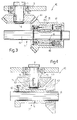
- a horizontal industrial conveyor for items 2 is generally indicated 1 and comprises a supporting base 3 of known type, a plurality of a known type of driven rollers 4, which are cylindrical and adjacently mounted, and rotatable about their axes with respect to the base 3, and operable simultaneously to support and advance items 2 along the conveyor 1, and common transmission means 5, only shown schematically in Figure 6, operable to drive the rollers 4 by transmitting to them the rotational movement imparted by one or more common motors which, again, are known and not illustrated for simplicity.
- the rollers 4 are freely mounted on the frame 3 by respective end support pins 8, on lateral ends 9 projecting from which there are freely carried, on at least one side of the rollers 4, respective toothed wheels 10 forming part of the common transmission means 5, which mesh with a respective roller chain 11, of known type, driven in a known way, not illustrated for simplicity, by the said common motors, in such a way as to drive the toothed wheels 10 to rotate at a constant velocity.
- each roller 4 The drive between the toothed wheels 10 and the respective rollers 4 is transmitted through the pins 8 by means of the device 7 of each roller 4; according to the invention, this comprises a pair of facing annular elements 14 and 15 which are not mechanically connected to one another and which are separated by a predetermined relatively small distance, for example, a few centimetres, and rigidly connected for rotation, the first with the wheel 10 and the second with the free end of the corresponding end 9 carrying the wheel 10.
- the element 14 is rigidly carried, by means of screws 16, by a hub 18 projecting from the corresponding wheel 10, and includes a disc 9 of sheet metal formed as a cup, provided on one face 20 with one or more magnets 21, disposed radially in a ring, whilst the element 15 is directly rigidly fixed to the end 9 of the pin 8 by means of a clamping screw 22 and includes a disc 23 in the form of a flywheel, provided on one face 24 with one or more magnets 25 similar to the magnets 21; a cap 27 completes and protects the device 7.
- the magnets 21 and 25 are permanent and, rather than being formed by a plurality of bi-polar elements disposed in a ring, are constituted by two respective permanent magnets of commercial type having six poles; and entirely equivalently, according to the present invention, one or both of the magnets 21 and 25 can be replaced by electromagnets of equal strength, of known type and not illustrated for simplicity, suitably fed for example through brushes carried by the cap 27, or the magnets of one of the elements 14 or 15 may be replaced with a ring made of ferromagnetic material in such a way that at least part of one of the elements 14,15 is made of a material capable of interacting magnetically with the magnet 21 or 25 (permanent or otherwise) of the other annular element facing it, in such a way as to cause mutual magnetic coupling of the elements 14 and 15 with consequent linking of the respective magnetic fields of these and transmission, by known physical laws, of movement between the elements 14 and 15 which are mechanically unconnected, in consequence of the attraction and/or repulsion phenomena of the respective poles; in fact
- the elements 14 and 15, instead of being formed by facing discs, are constituted by two concentric sleeves 46 and 47 provided laterally with a plurality of permanent magnets 21 and 25 disposed longitudinally in a ring; with such arrangement the maximum magnetic flux linkage is obtained and therefore higher couples can be transmitted.
- the devices 7 do not have bevel gear coupling, but rather the elements 14 and 15 are carried, the first rigidly on the shaft 41 together with all the other elements 14 of the other devices 7, and the second rigidly on the associated wheel 4, fixed to the associated pin 8, for example, with a key 50.
- the elements 14 and 15 comprise respective sleeves 51 at or adjacent ends of which there are fixed, in respective rings, permanent magnets 52 and 53 of frustoconical conformation; in this way transmission between orthogonal axes is ensured without bevel gears, even if the magnetic coupling is not optimal and therefore the transmissible couple is low.
Landscapes
- Engineering & Computer Science (AREA)
- Mechanical Engineering (AREA)
- Rollers For Roller Conveyors For Transfer (AREA)
Applications Claiming Priority (2)
| Application Number | Priority Date | Filing Date | Title |
|---|---|---|---|
| ITTO1985U53173U IT8553173U1 (it) | 1985-03-26 | 1985-03-26 | Trasportatore a rulli motorizzati con frizionamento magnetico |
| IT5317385U | 1985-03-26 |
Publications (2)
| Publication Number | Publication Date |
|---|---|
| EP0199045A2 true EP0199045A2 (de) | 1986-10-29 |
| EP0199045A3 EP0199045A3 (de) | 1987-04-29 |
Family
ID=11280564
Family Applications (1)
| Application Number | Title | Priority Date | Filing Date |
|---|---|---|---|
| EP86103170A Withdrawn EP0199045A3 (de) | 1985-03-26 | 1986-03-10 | Förderer mit angetriebenen Rollen mit magnetischer Kupplung |
Country Status (2)
| Country | Link |
|---|---|
| EP (1) | EP0199045A3 (de) |
| IT (1) | IT8553173U1 (de) |
Cited By (12)
| Publication number | Priority date | Publication date | Assignee | Title |
|---|---|---|---|---|
| FR2643619A1 (fr) * | 1989-02-28 | 1990-08-31 | Renault Automation | Dispositif a arbre traversant pour convoyeur a rouleaux a friction |
| US5188215A (en) * | 1991-06-07 | 1993-02-23 | Grob Werke Gmbh & Co. Kg | Apparatus for the transportation of goods to be conveyed |
| WO1997047541A1 (en) * | 1996-06-11 | 1997-12-18 | Vcs Control Systems Inc. | Motorized conveyor roller |
| GB2284105B (en) * | 1993-11-19 | 1998-03-04 | Maruyasu Kikai Kk | Conveyor |
| EP1132321A3 (de) * | 2000-03-06 | 2001-10-04 | Tgw-Transportgeräte Gmbh | Rollenförderer |
| WO2004000698A1 (de) * | 2002-06-24 | 2003-12-31 | Bleichert Förderanlagen GmbH | Transporteinrichtung mit hysteresekupplung |
| EP1394083A1 (de) * | 2002-08-30 | 2004-03-03 | GROB-Werke Burkhart Grob e.K. | Tranportvorrichtung zum Transport von Werkstücken |
| US20140305773A1 (en) * | 2013-04-16 | 2014-10-16 | Charles Agnoff | Slip clutch and roller conveyor incorporating same |
| US9688473B2 (en) | 2015-03-02 | 2017-06-27 | Lorin Reed | Conveying systems and methods of use |
| US10618740B2 (en) | 2017-11-22 | 2020-04-14 | Lorin Reed | Produce conveying and sizing equipment |
| IT202000005773A1 (it) | 2020-03-18 | 2020-06-18 | Rolle Monica | Sistema di trascinamento per trasportatore a catena di articoli |
| CN113548445A (zh) * | 2021-08-10 | 2021-10-26 | 衢州市川特电子科技有限公司 | 一种用于线路板输送的无接触式钕磁输送装置 |
Family Cites Families (10)
| Publication number | Priority date | Publication date | Assignee | Title |
|---|---|---|---|---|
| US2159657A (en) * | 1937-09-03 | 1939-05-23 | Pittsburgh Plate Glass Co | Magnetic drive for lehr rolls |
| US2436939A (en) * | 1943-10-21 | 1948-03-02 | Hoover Co | Magnetic coupling and bearing |
| FR1132230A (fr) * | 1954-10-13 | 1957-03-06 | Philips Nv | Dispositif pour transformer un mouvement continu de rotation en un mouvement alternatif de rotation ou inversement |
| FR1487492A (fr) * | 1966-05-27 | 1967-07-07 | Dispositif magnétique d'accouplement entre un arbre menant et un arbre mené | |
| DE2210927A1 (de) * | 1972-03-07 | 1973-09-13 | Kuester Hartmann Gmbh | Rollenfoerderstrecke |
| US3961700A (en) * | 1973-08-09 | 1976-06-08 | Fleischauer Fred J | Limited torque conveyor construction |
| DE3023334A1 (de) * | 1980-06-21 | 1982-01-07 | AKo Plan Automationsanlagen GmbH, 6200 Wiesbaden | Speicherrollenband als transportsystem |
| US4469220A (en) * | 1981-12-16 | 1984-09-04 | Tri-Veyor Corp. | Magnetic coupling assembly for accumulating power roll conveyor |
| NL8200857A (nl) * | 1982-03-03 | 1983-10-03 | Speciaalmachinefabriek J H Van | Aangedreven rol voor een rollentransportbaan. |
| DE3210167A1 (de) * | 1982-03-19 | 1983-09-29 | Franz Klaus Union Armaturen, Pumpen Gmbh & Co, 4630 Bochum | Vorrichtung zur drehmomentbegrenzung |
-
1985
- 1985-03-26 IT ITTO1985U53173U patent/IT8553173U1/it unknown
-
1986
- 1986-03-10 EP EP86103170A patent/EP0199045A3/de not_active Withdrawn
Cited By (21)
| Publication number | Priority date | Publication date | Assignee | Title |
|---|---|---|---|---|
| FR2643619A1 (fr) * | 1989-02-28 | 1990-08-31 | Renault Automation | Dispositif a arbre traversant pour convoyeur a rouleaux a friction |
| EP0385849A1 (de) * | 1989-02-28 | 1990-09-05 | Renault Automation | Vorrichtung mit durchgehender Welle für einen Förderer mit Friktionsrollen |
| US5188215A (en) * | 1991-06-07 | 1993-02-23 | Grob Werke Gmbh & Co. Kg | Apparatus for the transportation of goods to be conveyed |
| GB2284105B (en) * | 1993-11-19 | 1998-03-04 | Maruyasu Kikai Kk | Conveyor |
| US5899320A (en) * | 1993-11-19 | 1999-05-04 | Maruyasu Kikai Co. Ltd. | Conveyor |
| WO1997047541A1 (en) * | 1996-06-11 | 1997-12-18 | Vcs Control Systems Inc. | Motorized conveyor roller |
| EP1132321A3 (de) * | 2000-03-06 | 2001-10-04 | Tgw-Transportgeräte Gmbh | Rollenförderer |
| WO2004000698A1 (de) * | 2002-06-24 | 2003-12-31 | Bleichert Förderanlagen GmbH | Transporteinrichtung mit hysteresekupplung |
| EP1394083A1 (de) * | 2002-08-30 | 2004-03-03 | GROB-Werke Burkhart Grob e.K. | Tranportvorrichtung zum Transport von Werkstücken |
| US7014037B2 (en) | 2002-08-30 | 2006-03-21 | Grob-Werke Burkhart Grob E.K. | Conveying device for conveying workpieces |
| US20140305773A1 (en) * | 2013-04-16 | 2014-10-16 | Charles Agnoff | Slip clutch and roller conveyor incorporating same |
| US9688473B2 (en) | 2015-03-02 | 2017-06-27 | Lorin Reed | Conveying systems and methods of use |
| US10118769B2 (en) | 2015-03-02 | 2018-11-06 | Lorin Reed | Conveying systems and methods of use |
| US10457491B2 (en) | 2015-03-02 | 2019-10-29 | Lorin Reed | Conveying systems and methods of use |
| US10815065B2 (en) | 2015-03-02 | 2020-10-27 | Lorin Reed | Conveying systems and methods of use |
| US10618740B2 (en) | 2017-11-22 | 2020-04-14 | Lorin Reed | Produce conveying and sizing equipment |
| US10934098B2 (en) | 2017-11-22 | 2021-03-02 | Lorin Reed | Methods of conveying and sizing produce |
| US11319157B2 (en) | 2017-11-22 | 2022-05-03 | Lorin Reed | Produce conveying and sizing equipment |
| IT202000005773A1 (it) | 2020-03-18 | 2020-06-18 | Rolle Monica | Sistema di trascinamento per trasportatore a catena di articoli |
| CN113548445A (zh) * | 2021-08-10 | 2021-10-26 | 衢州市川特电子科技有限公司 | 一种用于线路板输送的无接触式钕磁输送装置 |
| CN113548445B (zh) * | 2021-08-10 | 2023-03-10 | 衢州市川特电子科技有限公司 | 一种用于线路板输送的无接触式钕磁输送装置 |
Also Published As
| Publication number | Publication date |
|---|---|
| IT8553173V0 (it) | 1985-03-26 |
| IT8553173U1 (it) | 1986-09-26 |
| EP0199045A3 (de) | 1987-04-29 |
Similar Documents
| Publication | Publication Date | Title |
|---|---|---|
| US3936683A (en) | Magnetic coupling | |
| US3610406A (en) | Conveyor constructions and torque-limiting transmissions therefor | |
| EP3818917A1 (de) | Berührungslose magnetkupplung für lebensmittelverarbeitungsgeräte mit kleinem bürstenlosen permanentmagnetmotor | |
| AU1476502A (en) | Conveyor system | |
| JP6199087B2 (ja) | 仕分け装置 | |
| US2193214A (en) | Electromagnetic control | |
| DE3915556A1 (de) | Vorrichtung und verfahren zum montieren elektrischer bauteile | |
| WO2012125985A4 (en) | Automated power generator | |
| US20200136492A1 (en) | Improved magnetic clutch assembly | |
| EP0199045A3 (de) | Förderer mit angetriebenen Rollen mit magnetischer Kupplung | |
| EP1340309B1 (de) | Verfahren und vorrichtung zur magnetischen kraftübertragung | |
| US2745549A (en) | Magnetic separator | |
| US10723562B2 (en) | Axial flux motor for a conveyor | |
| CN209796702U (zh) | 一种摆轮分拣设备 | |
| US2411055A (en) | Magnetic clutch | |
| FR2476779B1 (de) | ||
| US3979652A (en) | Electromagnetic motor utilizing attraction and repulsion forces | |
| US1963642A (en) | Electromagnetic transmission | |
| US3659126A (en) | Magnetic torque control coupling | |
| SU864458A1 (ru) | Бесконтактна магнитна муфта-редуктор | |
| JP4666341B2 (ja) | ローラコンベヤ | |
| JPS591417Y2 (ja) | うず電流クラツチ・ブレ−キ | |
| JPH09317840A (ja) | 磁気ネジ搬送装置 | |
| GB2158541A (en) | Synchronised coupling means | |
| EP0067112A1 (de) | Wickelmaschine mit beweglichem Arm für ein Kernelement mit Aussennuten einer dynamo-elektrischen Maschine |
Legal Events
| Date | Code | Title | Description |
|---|---|---|---|
| PUAI | Public reference made under article 153(3) epc to a published international application that has entered the european phase |
Free format text: ORIGINAL CODE: 0009012 |
|
| AK | Designated contracting states |
Kind code of ref document: A2 Designated state(s): AT BE CH DE FR GB LI LU NL SE |
|
| PUAL | Search report despatched |
Free format text: ORIGINAL CODE: 0009013 |
|
| AK | Designated contracting states |
Kind code of ref document: A3 Designated state(s): AT BE CH DE FR GB LI LU NL SE |
|
| STAA | Information on the status of an ep patent application or granted ep patent |
Free format text: STATUS: THE APPLICATION IS DEEMED TO BE WITHDRAWN |
|
| 18D | Application deemed to be withdrawn |
Effective date: 19870430 |
|
| RIN1 | Information on inventor provided before grant (corrected) |
Inventor name: MORICONI, MARCELLO |