EP0198511B1 - Appareil de reproduction/d'enregistrement magnétique - Google Patents
Appareil de reproduction/d'enregistrement magnétique Download PDFInfo
- Publication number
- EP0198511B1 EP0198511B1 EP86105425A EP86105425A EP0198511B1 EP 0198511 B1 EP0198511 B1 EP 0198511B1 EP 86105425 A EP86105425 A EP 86105425A EP 86105425 A EP86105425 A EP 86105425A EP 0198511 B1 EP0198511 B1 EP 0198511B1
- Authority
- EP
- European Patent Office
- Prior art keywords
- erasing
- heads
- head
- tape
- magnetic recording
- Prior art date
- Legal status (The legal status is an assumption and is not a legal conclusion. Google has not performed a legal analysis and makes no representation as to the accuracy of the status listed.)
- Expired - Lifetime
Links
- 230000005236 sound signal Effects 0.000 claims description 15
- 239000011295 pitch Substances 0.000 description 12
- 230000014509 gene expression Effects 0.000 description 7
- 238000010586 diagram Methods 0.000 description 3
- 238000006073 displacement reaction Methods 0.000 description 2
- 238000004458 analytical method Methods 0.000 description 1
- 238000003491 array Methods 0.000 description 1
- 239000003990 capacitor Substances 0.000 description 1
- 238000000034 method Methods 0.000 description 1
Images


Classifications
-
- G—PHYSICS
- G11—INFORMATION STORAGE
- G11B—INFORMATION STORAGE BASED ON RELATIVE MOVEMENT BETWEEN RECORD CARRIER AND TRANSDUCER
- G11B5/00—Recording by magnetisation or demagnetisation of a record carrier; Reproducing by magnetic means; Record carriers therefor
- G11B5/02—Recording, reproducing, or erasing methods; Read, write or erase circuits therefor
- G11B5/024—Erasing
-
- G—PHYSICS
- G11—INFORMATION STORAGE
- G11B—INFORMATION STORAGE BASED ON RELATIVE MOVEMENT BETWEEN RECORD CARRIER AND TRANSDUCER
- G11B15/00—Driving, starting or stopping record carriers of filamentary or web form; Driving both such record carriers and heads; Guiding such record carriers or containers therefor; Control thereof; Control of operating function
- G11B15/02—Control of operating function, e.g. switching from recording to reproducing
- G11B15/12—Masking of heads; circuits for Selecting or switching of heads between operative and inoperative functions or between different operative functions or for selection between operative heads; Masking of beams, e.g. of light beams
- G11B15/14—Masking or switching periodically, e.g. of rotating heads
-
- G—PHYSICS
- G11—INFORMATION STORAGE
- G11B—INFORMATION STORAGE BASED ON RELATIVE MOVEMENT BETWEEN RECORD CARRIER AND TRANSDUCER
- G11B5/00—Recording by magnetisation or demagnetisation of a record carrier; Reproducing by magnetic means; Record carriers therefor
- G11B5/008—Recording on, or reproducing or erasing from, magnetic tapes, sheets, e.g. cards, or wires
- G11B5/00813—Recording on, or reproducing or erasing from, magnetic tapes, sheets, e.g. cards, or wires magnetic tapes
- G11B5/00847—Recording on, or reproducing or erasing from, magnetic tapes, sheets, e.g. cards, or wires magnetic tapes on transverse tracks
- G11B5/0086—Recording on, or reproducing or erasing from, magnetic tapes, sheets, e.g. cards, or wires magnetic tapes on transverse tracks using cyclically driven heads providing segmented tracks
-
- G—PHYSICS
- G11—INFORMATION STORAGE
- G11B—INFORMATION STORAGE BASED ON RELATIVE MOVEMENT BETWEEN RECORD CARRIER AND TRANSDUCER
- G11B5/00—Recording by magnetisation or demagnetisation of a record carrier; Reproducing by magnetic means; Record carriers therefor
- G11B5/008—Recording on, or reproducing or erasing from, magnetic tapes, sheets, e.g. cards, or wires
- G11B5/00813—Recording on, or reproducing or erasing from, magnetic tapes, sheets, e.g. cards, or wires magnetic tapes
- G11B5/00878—Recording on, or reproducing or erasing from, magnetic tapes, sheets, e.g. cards, or wires magnetic tapes transducing different track configurations or formats on the same tape
-
- G—PHYSICS
- G11—INFORMATION STORAGE
- G11B—INFORMATION STORAGE BASED ON RELATIVE MOVEMENT BETWEEN RECORD CARRIER AND TRANSDUCER
- G11B5/00—Recording by magnetisation or demagnetisation of a record carrier; Reproducing by magnetic means; Record carriers therefor
- G11B5/48—Disposition or mounting of heads or head supports relative to record carriers ; arrangements of heads, e.g. for scanning the record carrier to increase the relative speed
- G11B5/52—Disposition or mounting of heads or head supports relative to record carriers ; arrangements of heads, e.g. for scanning the record carrier to increase the relative speed with simultaneous movement of head and record carrier, e.g. rotation of head
- G11B5/53—Disposition or mounting of heads on rotating support
- G11B5/531—Disposition of more than one recording or reproducing head on support rotating cyclically around an axis
Definitions
- the present invention generally relates to a helical scan type magnetic recording/reproducing apparatus for domenstic use. More particulary, the invention concerns a magnetic recording/reproducing apparatus in which each of slant tracks formed on a magnetic tape is divided into a plurality of sub-tracks or areas in the longitudinal direction of the track, wherein audio signals undergone a pulse code modulation (hereinafter referred to as PCM audio signal) are each recorded or reproduced on or from the sub-tracks (areas or channels) resulting from the division.
- PCM audio signal audio signals undergone a pulse code modulation
- the helical scan type magnetic video recording/reproducing apparatus (such as a VTR) for domestic use has a rotatable cylinder on which magnetic heads are mounted with an angular displacement of appoximately 180° therebetween.
- a magnetic tape is wound or wrapped slant around the periphery of the cylinder over an angular range of appoximately 180°, whereby video signal is recorded on the record track formed slant relative to the direction in which the magnetic tape is transported.
- the record track is divided in a plurality of sub-tracks or areas in the direction trackwise and that PCM audio signal is recorded or reproduced on or from each of the areas resulting from the track division instead of the video signal.
- a single video track is divided into six sub-tracks or areas in the longitudinal direction of the track to thereby prepare first to sixth channels.
- PCM audio signal is recorded only on the first channel while no recording is made on the second to sixth channels. This recording operation is performed sequentially on the adjacent tracks from one to another.
- the sub-track or area corresponding to the second channel is subjected to the recording sequentially on the track basis (i.e from track to track).
- the magnetic video recording/reproducing apparatus includes an erasing head which has a width large enough to erase the record widthwise over the whole width of the magnetic tape. Consequently, when the video track is divided into six sub-tracks or areas for recording different PCM audio signals on the six corresponding channels, respectively, it is impossible to selectively erase only the desired channel for the purpose of recording again a new PCM audio signal thereon.
- the document AT-B-365 354 aims at writing the track pilot signal without reducing their power.
- This document shows an erasing head which is stationary and not adjustable. This head is used for recording pilot track signals as well as for erasing every existing track several times. Thus, this document does not foresee the selective erasing of a desired channel.
- This prior art document does not mention anything about backward operation mode which is of essential importance for the goal and configuration of the present invention, wherein the selective erasing is foreseen for forward as well as for backward operation mode.
- the document EP-A-0 190 695 is a non-prepublished document which discloses a recording/reproducing apparatus containing two magnetic recording heads and two erasing heads. One erasing head is operable when the tape travels in the forward direction and the other erasing head is operable when the tape travels in the backward direction.
- the invention relates to a magnetic recording/reproducing apparatus which includes a first flying erasing head put into operation in the forward tape transporting direction, and a second flying erasing head put into operation in the backward tape transporting direction, both of the flying erasing heads being mounted on a rotatable cylinder at respective positions selectively determined so as to ensure satisfactory erasing characteristic or performance, so that PCM audio signal can be recorded on each of areas or sub-tracks resulting from the division of each track into six, regardless of whether the magnetic tape is transported in the forward direction or backward direction.
- the object of the present invention is obtained by the apparatus defined in the claims.
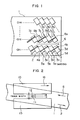
- Fig. 1 shows a record pattern on a magnetic surface of a magnetic tape 1.
- each of the tracks is divided into areas of a first channel CH 1, a second channel CH 2, ..., and a sixth channel CH 6, respectively, sequentially from the bottom, as viewed in the figure, wherein PCM audio signals are recorded on the areas of the respective channels.
- This recording system will be referred to as the multi-channel PCM system.
- For erasing the record it is required that records on the individual channels can be erased independently and separately from one another. To this end, there are employed flying erasing heads according to the teaching of the invention.
- the flying erasing head is so designed to have a tracking width Tw' which is at least twice larger than the track pitch P T (i.e Tw' ⁇ 2P T ) so that two tracks can be simultaneously erased.
- Tw' tracking width
- P T track pitch
- a numeral 10 denotes an upper cylinder
- 15 denotes a lower cylinder
- 16 denotes an arrow indicating a rotational direction of the cylinder
- 11 denotes a video head
- 13 denotes a bottom face of the video head
- a numeral 14 denotes a top face of the video head
- a numeral 12 denotes a head gap.
- positions indicated by arrows 5a, 5b, 5c and 5d are determined by the bottom face of the video head 11, as is illustrated in Fig. 1 for the first channel CH 1.
- positions of arrows 9a, 9b and 9c are determined by the top face 14 of the video head 11, as is illustrated for the second channel CH 2 in Fig. 1. Accordingly, in order to inhibit the flying erasing head from erasing the newly recorded track, it is necessary to mount the flying erasing head on the cylinder at such position in which the bottom face of the flying erasing head is aligned with the position of the arrow 5a or 5c, respectively, as indicated by symbols 4a and 4b, for the first channel CH 1, i.e. when the tape is transported in the forward direction. Similarly, for the second channel, i.e. in case the tape is transported in the backward direction, it is requried that the top face of the flying erasing head is aligned with the position of the arrow 9a or 9c, respectively, as indicated by symbols 8a and 8b.
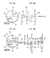
- Figs. 3A and 3B are views for illustrating a head mounting arrangement in a two-head type video tape recorder or VTR. More specifically, Fig. 3A shows disposition of the heads on the cylinder, and Fig. 3B illustrates inter-head offsets.
- a reference numeral 17 denotes a cylinder
- 18 and 19 denote video heads, respectively
- 20 denotes a flying erasing head which is put into operation only for the forward tape transporting operation mode
- 21 denotes a flying erasing head put into operation only for the backward tape transporting operation mode.
- the track pitch P T is 20 ⁇ m
- the tracking width Tw of the video heads 18 and 19 is 20 ⁇ m
- an offset ⁇ H indicated by a double-head arrow 22 is provided so that the bottom face of the flying erasing head 20 for the forward operation mode only is higher than the bottom faces of the video head 18 and 19 by 10 ⁇ m while the top face of the flying erasing head 21 for the backward operation mode only is lower than the top faces of the video heads 18 and 19 by 10 ⁇ m, as indicated in Fig. 3B.
- the offset ⁇ H can be expressed in terms of the track pitch P T and the angle ⁇ as follows:
- the track pitch in the operation mode in which the magnetic tape is transported at a standard speed v (hereinafter referred to as the standard recording mode or simply as SP mode) is represented by P T1 while the track pitch in the operation mode in which the magnetic tape is transported at a speed v n where n represents an integer greater than 2 (hereinafter referred to as an extended time recording mode or simply as LP mode) is represented by P T2 .
- the offset ⁇ H is selected to be ( ⁇ .P T1 )/180 ⁇ m which in turn is determined by the track pitch P T in the SP mode, the offset ⁇ H will be excessively large for the LP mode, involving however no danger that newly recorded track might be erased.
- the offset ⁇ H is selected to be ( ⁇ .P T2 )/180 ⁇ m which is determined by the track pitch P T2 in the LP mode, the offset ⁇ H is excessively small for the SP mode, resulting in undesirable erasure of the newly recorded track. Accordingly, it is necessary that the offset ⁇ H be determined on the basis of the track pitch P T1 for the SP mode in accordance with the expression (1).
- a head mounting arrangement in a four-head type VTR will be described by referring to Figs. 4A and 4B of which Fig. 4A shows a head disposition on the cylinder and Fig. 4B illustrates the inter-head offsets.
- a reference numeral 24 denotes a cylinder
- 25 and 26 denote video heads for the LP mode (hereinafter referred to as LP head)
- 27 and 28 denote video heads for the SP mode (hereinafter referred to as SP head)
- 29 denotes a flying erasing head destined only for the forward tape transporting operation mode
- a numeral 30 denotes a flying erasing head destined only for the backward tape transporting operation mode.
- angles ⁇ 1 and ⁇ 2 are 60° and 120°, respectively
- the tracking width of the SP head is represented by Tw1
- the tracking width of the LP head is Tw2
- the track pitch in the LP mode is P T1
- the track pitch in the SP mode is represented by P T2 .
- the offsets relative to the SP head and LP head are represented by ⁇ H1 and ⁇ H2, respectively, they can be given by the following expressions in accordance with the expression (1).
- the tracking widths Tw1 and Tw2 are, respectively, restricted within the ranges defined as follows: Furthermore, since the SP head 27 and the LP head 25 are mounted to be aligned with each other along the center line of the track, as in illustrated in Fig. 4B, the bottom face of the SP head 27 is lower than that of the LP head 25 by (Tw1 - Tw2)/2. It is now assumed that the offset of the flying erasing head 29 is set with reference to the bottom face of the LP head 25. On the assumption, the offset 31 of the bottom face of the flying erasing head 29 relative to that of the SP head 27 is given by ⁇ H2 + (Tw1 - Tw2)/2.
- the top face of the SP head 28 is higher than that of the LP head 26 by (Tw1 - Tw2)/2, whereby the offset 33 between the top face of the SP head 28 and that of the flying erasing head 30 is given by ⁇ H2 + (Tw1 - Tw2)/2.
- Tw1 20 ⁇ m
- Tw2 15 ⁇ m
- P T1 20 ⁇ m
- P T2 10 ⁇ m.
- ⁇ H2 6.7 ⁇ m.
- double-azimuth head array means a combination or assembly of two heads having different azimuth angles and disposed close to each other with a distance corresponding to a value in a range of 0.5 H to several H (where H represents a horizontal scan period).
- a reference numeral 35 denotes a cylinder
- numerals 36 and 37 denote SP heads having, respectively, plus (+) azimuth and minus (-) azimuth (hereinafter referred to as SP (+) head and SP (-) head, respectively)
- numerals 38 and 39 denote LP heads having, respectively, minus (-) azimuth and plus (+) azimuth (hereinafter referred to as LP (+) head and LP (-) head, respectively)
- a numeral 40 denotes a flying erasing head operative only in the forward tape transporting direction
- a numeral 41 denotes a flying erasing head operative only in the backward tape transporting direction.
- the heads 36 and 38 and the heads 37 and 39 constitute, respectively, the double-azimuth head array in which the gap distance is in the range of 0.5 H to several H, as defined above.
- Fig. 5B is a view for illustrating the offsets among the various heads. It will be seen that the SP heads 36 and 37 and the LP heads 38 and 39 are, respectively, so mounted that the tracking centers thereof coincide with each other. It is assumed that the tracking widths of the SP heads 36, 37 and the LP heads 38, 39 are represented by Tw1 and Tw2, respectively, and that the track pitches are by P T1 and P T2 .
- the flying erasing heads 40 and 41 are mounted with an angular distance ⁇ relative to the video heads 36, 37, 38 and 39
- the flying erasing heads 40 and 41 may be mounted with an offset of ( ⁇ .P T1 )/180 relative to the SP heads 36 and 37 and with an offset of ( ⁇ .P T2 )/180 relative to the LP heads 38 and 39, wherein the following relation applies valid: Since the tracking centers of the video heads 36, 37 and 38, 39 coincide with each other, the bottom face of the SP head (36, 37) is lower than that of the LP head (38, 39) by (Tw1 - Tw2)/2, while the top face of the SP head is higher than that of the LP head by (Tw1 - Tw2)/2.
- Figs. 6A and 6B show a specific version of the arrangement shown in Figs. 5A and 5B.
- Tw1 20 ⁇ m
- Tw2 15 ⁇ m
- P T2 10 ⁇ m.
- the angle ⁇ is selected to be 45°.
- ⁇ H1 5 ⁇ m
- ⁇ H2 2.5 ⁇ m
- (Tw1 - Tw2)/2 2.5 ⁇ m.
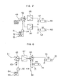
- Figs. 7 and 8 description will be made on the erasing circuit according to an exemplary embodiment of the invention by referring to Figs. 7 and 8.
- the different flying erasing heads are employed in the forward and backward tape transporting directions, respectively, with the offset being varied, simultaneous current supply to both the flying erasing heads results in erasure of the newly recorded track. Accordingly, it is necessary to change over the erasing current between the forward tape transporting mode and the backward tape transporting mode.
- Fig. 7 shows an erasing circuit in which two erasing amplifiers 55 and 56 are employed
- Fig. 8 shows an erasing circuit in which a single erasing amplifier 57 is employed.
- a reference numeral 55 denotes an erasing amplfier only for the forward tape transporting mode
- 57 denotes a rotary transformer
- 59 denotes a flying erasing head
- 56 denotes an erasing amplfier only for the backward tape transporting mode
- a numeral 60 denotes another flying erasing head.
- the change-over of the erasing current is effected by a switch 50 in dependence on the logical output of an AND gate 54 having the inputs supplied with a recording/reproduction indentifying signal REC, a channel change-over signal CH representative of the change-over of channel and a forward/backward tape transporting mode indentifying signal F/R, respectively.
- Fig. 9 shows a timing diagram.
- the recording/reproduction indentifying signal REC assumes a low level, whereby the switch 50 is closed to a contact b .
- the recording/reproduction identifying signal REC assumes a high level.
- a current Ih1 flows constantly to the head 59 operative in the forward tape transportation.
- the switch 50 is closed to a contact a .
- a signal A represents a head change-over signal of 30 Hz derived from a pulse signal which is supplied from a tachogenerator coupled operatively to the rotating cylinder and carrying phase information.
- the channel change-over signal CH assumes a high level at the position corresponding to the first channel CH 1, as previously described by referring to Fig. 1, resutling in that the head 59 operative in the forward tape transporting mode is supplied with the current Ih1.
- the backward/forward identifying signal F/R assumes a high level, while the channel change-over signal CH becomes high at the position corresponding to the second channel CH 2, resutling in that a current Ih2 flows to the head 60 operative only in the backward tape transporting mode.
- the switch 50 is closed to a contact c .
- the change-over between the erasing currents Ih1 and Ih2 for the forward and backward transportation modes is effected by a switch 68 on the output side of the erasing amplifier 67.
- the turning-on/off of the erasing signal is effected by a switch 62 connected in precedence to the erasing amplifier 67.
- the switch 62 is closed to a contact b , whereby the erasing signal is blocked.
- Fig. 10 shows in concrete an exemplary arrangement of the erasing current change-over circuit shown in Fig. 8.
- a reference numeral 74 denotes an erasing signal input terminal
- 75 denotes an input terminal for signal REC.CH representative of an inverted sum signal of the REC and CH signals.
- a transistor Q1 is biased to allow the erasing signal applied to the input terminal 74 to be amplified through the transistors Q1 and Q2, wherein the output signal (erasing signal) of the transistor Q2 is supplied to emitters of transistors Q3 and Q4, respectively.
- the transistor Q3 When the signal F/R applied to a terminal 76 is high, the transistor Q3 is turned on, allowing the erasing signal to flow to the head 72 operative in the forward tape transporting mode. On the other hand, when the signal F/R is at a low level, the transistor Q4 is turned on, resulting in that the erasing signal is supplied to the head 73 operative in the backward tape transporting mode.
- An inductance L1 serves to turning on the transistor Q3 or Q4. This inductance is required to be set at a sufficiently large value when compared with the inductance of the head 72 or 73.
- Capacitors C2 and C3 cooperate with the heads 72 and 73 to constitute resonance circuits, respectively, which are effective for reducing the effective power supplied to the stator sides of the rotary transformers 70 and 71, respectively.
- the complete erasure of the record track can be accomplished upon recording on the magnetic tape transported in either the forward or backward direction.
- the erasing system of the two-head type magnetic recording/reproduction apparatus as well as the four-head type magnetic recording/reproduction apparatus having both SP and LP modes can be realized with a minimum number of the flying erasing heads.
Landscapes
- Recording Or Reproducing By Magnetic Means (AREA)
Claims (3)
- Dispositif d'enregistrement et de lecture magnétique, dans lequel(a) une bande magnétique (1) est enroulée autour d'un cylindre rotatif (17;24;35) et peut se déplacer à la fois dans le sens d'avance et dans le sens rétrograde, le dispositif comprenant:(b) une unité à têtes d'enregistrement/lecture magnétique, montée sur ledit cylindre rotatif;(c) une unité à têtes d'effacement comprenant des première et seconde têtes d'effacement montées également sur ledit cylindre sensiblement à une distance angulaire de 180°, ladite première tête d'effacement (29;40;45;59; 72) pouvant être actionnée lorsque ladite bande se déplace dans le sens d'avance, et ladite seconde tête d'effacement (30;41;46;60;73) pouvant être actionnée lorsque ladite bande se déplace dans le sens rétrograde;(d) un circuit permettant le traitement de signaux audio de sorte que des signaux audio MIC séparés individuellement sont enregistrés et lus dans différents canaux de pistes d'enregistrement, en lesquels sont subdivisées des pistes obliques d'enregistrement situées sur ladite bande magnétique, chaque canal des pistes d'enregistrement étant formé par une suite de parties de pistes d'enregistrement, d'une longueur prédéterminée, produites par ladite subdivision et s'étendant dans la direction longitudinale de ladite bande magnétique; et(e) un circuit d'effacement (figures 7,8,10) associé auxdites première et seconde têtes d'effacement pour l'envoi, lorsqu'un effacement de piste est demandé, d'un signal d'effacement (Ih1 ou Ih2) à l'une desdites têtes d'effacement sur la base d'un signal (F/R) de discrimination du sens de déplacement de la bande et d'un signal (CH) spécifiant le canal, et dans lequel(f) ladite unité à têtes d'enregistrement/lecture magnétique comporte au moins quatre têtes d'enregistrement/lecture magnétique (25-28; 36-39) disposées sur ledit cylindre de telle sorte que la position du centre des parties formant entrefer des têtes d'enregistrement/lecture, telle qu'elle est vue dans la direction de la largeur des pistes d'enregistrement, est sensiblement la même, lesdites au moins quatre têtes d'enregistrement/lecture magnétique comprenant des premier et second couples de têtes d'enregistrement/lecture magnétique, ledit premier couple de têtes d'enregistrement/lecture magnétique possédant une largeur de piste supérieure à celle dudit second couple de têtes d'enregistrement/lecture magnétique, les têtes d'enregistrement/lecture magnétique de chaque couple de têtes d'enregistrement/lecture magnétique étant séparées l'une de l'autre sensiblement par une distance angulaire de 180° sur le cylindre;(g) ladite première tête d'effacement située sur ledit cylindre est agencée de manière à présenter un premier décalage par rapport audit premier couple de têtes d'enregistrement/lecture magnétique, lorsqu'on regarde dans la direction de la largeur de la piste d'enregistrement; et(h) ladite seconde tête d'effacement située sur ledit cylindre est agencée de manière à présenter un second décalage par rapport audit premier couple de têtes d'enregistrement/lecture magnétique, lorsqu'on regarde dans la direction de la largeur de la piste d'enregistrement.
- Dispositif selon la revendication 1, caractérisé en ce que :(a) la largeur de piste de chacune desdites première et seconde têtes d'effacement n'est pas sensiblement inférieure au double du pas des pistes (distance de piste à piste) PT1 pour ledit premier couple de têtes d'enregistrement/lecture magnétique (27;28;36;37) dans lesdites pistes d'enregistrement; et(b) la disposition desdites première et seconde têtes d'effacement (29,30;40,41;45,46) sur ledit cylindre est telle que(b1) lesdites première et seconde têtes d'effacement sont situées en avant, sensiblement d'un premier angle prédéterminé ϑ₁, par rapport audit premier couple de têtes d'enregistrement/lecture magnétique (27,28; 36,37) et en avant, sensiblement d'un second angle prédéterminé ϑ₂, par rapport audit second couple de têtes d'enregistrement/lecture magnétique (25,26; 38,39), avec 0° < ϑ₁ < 180° et 0° < ϑ₂ < 180°,(b2) ledit premier décalage de ladite première tête d'effacement (29;40;45) par rapport audit premier couple de têtes d'enregistrement/lecture magnétique (27,28;36,37) est un décalage, dont une face d'extrémité de ladite première tête d'effacement, qui détermine son extrémité de démarrage de la trace de la bande de chaque canal de pistes d'enregistrement pour ledit premier sens de déplacement d'avance de la bande, est décalée en direction d'une ligne centrale des têtes d'enregistrement/lecture magnétique dans le sens de déplacement de la bande, de sorte que ladite face d'extrémité de ladite première tête d'effacement (29;40;45) est écartée d'une extrémité d'une tête (27;36) dudit premier couple de têtes d'enregistrement/lecture magnétique (27,28;36,37), qui détermine son extrémité de démarrage de la trace de la bande de chaque canal de pistes d'enregistrement pour ledit sens de déplacement d'avance de la bande,(b3) ledit second décalage de ladite seconde tête d'effacement (30;41;46) par rapport audit premier couple de têtes d'enregistrement/lecture magnétique (27,28;36,37) est un décalage, dont une face d'extrémité de ladite seconde tête d'effacement, qui détermine son extrémité de démarrage de la trace de bande de chaque canal de pistes d'enregistrement pour ledit sens de déplacement rétrograde de la bande, est décalée en direction de ladite ligne centrale de sorte que ladite première face d'extrémité de ladite seconde tête d'effacement (30;41;46) est écartée d'une extrémité de l'autre tête (28; 37) dudit premier couple de têtes d'enregistrement/lecture magnétique (27,28;36,37) qui détermine son extrémité de démarrage de trace de bande de chaque canal de pistes d'enregistrement pour ledit sens de déplacement rétrograde de la bande, et(b4) les valeurs desdits premier et second décalages sont définies sensiblement comme étant égales à ϑ₁.PT1/180°.
- Dispositif d'enregistrement et de lecture magnétique, dans lequel(a) une bande magnétique (1) est enroulée autour d'un cylindre rotatif (17;24;35) et peut se déplacer à la fois dans le sens d'avance et dans le sens rétrograde, le dispositif comprenant:(b) au moins deux têtes d'enregistrement/lecture magnétique (18,19;25-28;36-39) montées sur ledit cylindre rotatif à une distance angulaire réciproque d'environ 180° et une unité à têtes d'effacement également montée sur le cylindre pour effacer simultanément des pistes d'enregistrement;(c) un circuit permettant le traitement de signaux audio de sorte que des signaux audio MIC séparés individuellement sont enregistrés et lus dans différents canaux de pistes d'enregistrement, en lesquels sont subdivisées des pistes obliques d'enregistrement situées sur ladite bande magnétique, chaque canal des pistes d'enregistrement étant formé par une suite de parties de pistes d'enregistrement, d'une longueur prédéterminée, produites par ladite subdivision et s'étendant dans la direction longitudinale de ladite bande magnétique;(d) ladite unité à têtes d'effacement comprend une première tête d'effacement (20;29;40;45;59;72) pouvant être actionnée lorsque ladite bande se déplace dans le sens d'avance, et une seconde tête d'effacement (21;30;41;46;60;73) pouvant être actionnée lorsque ladite bande se déplace dans le sens rétrograde;(e) lesdites au moins deux têtes d'enregistrement/lecture magnétique situées sur ledit cylindre sont disposées de telle sorte que la position du centre des parties formant entrefers des têtes, lorsqu'on regarde dans la direction de la largeur de la piste d'enregistrement, est sensiblement la même; et(f) un circuit d'effacement (figures 7,8,10) associé auxdites première et seconde têtes d'effacement pour l'envoi, lorsqu'un effacement de piste est demandé, d'un signal d'effacement (Ih1 ou Ih2) à l'une desdites têtes d'effacement sur la base d'un signal (F/R) de discrimination du sens de déplacement de la bande et d'un signal (CH) spécifiant le canal,
et dans lequel(g) la largeur de piste de chacune desdites première et seconde têtes d'effacement n'est sensiblement pas inférieure au double du pas des pistes PT dans lesdites pistes d'enregistrement; et(h) la disposition desdites première et seconde têtes d'effacement sur ledit cylindre est telle que lesdites première et seconde têtes d'effacement sont situées respectivement en avance, d'un angle prédéterminé ϑ, par rapport à ladite première tête magnétique et ladite autre tête magnétique, avec 0° < ϑ < 180°, et une face d'extrémité de ladite première tête d'effacement déterminant son extrémité de démarrage de trace de bande de chaque canal de pistes d'enregistrement pour ledit sens de déplacement d'avance de la bande est décalée dudit premier décalage (ΔH) vers une ligne centrale de la tête d'enregistrement/lecture magnétique dans la direction de déplacement de la bande à partir d'une première face d'extrémité de ladite première tête magnétique déterminant son extrémité de démarrage de trajet de la bande de chaque canal de pistes d'enregistrement pour ledit sens de déplacement d'avance de la bande, et une première face d'extrémité de ladite seconde tête d'effacement déterminant son extrémité de démarrage de la trace de la bande de chaque canal de pistes d'enregistrement pour ledit sens de déplacement rétrograde de la bande est décalée, dudit second décalage (ΔH), en direction de ladite ligne centrale à partir d'une première face d'extrémité de ladite autre tête d'enregistrement/lecture magnétique déterminant son extrémité de démarrage de trace de la bande de chaque canal de pistes d'enregistrement pour ledit sens de déplacement rétrograde de la bande, et lesdits premier et second décalages étant tous deux définis par ΔH = ϑ.PT/180°.
Applications Claiming Priority (2)
| Application Number | Priority Date | Filing Date | Title |
|---|---|---|---|
| JP82433/85 | 1985-04-19 | ||
| JP60082433A JPH0736203B2 (ja) | 1985-04-19 | 1985-04-19 | 磁気記録再生装置 |
Publications (2)
| Publication Number | Publication Date |
|---|---|
| EP0198511A1 EP0198511A1 (fr) | 1986-10-22 |
| EP0198511B1 true EP0198511B1 (fr) | 1991-07-31 |
Family
ID=13774424
Family Applications (1)
| Application Number | Title | Priority Date | Filing Date |
|---|---|---|---|
| EP86105425A Expired - Lifetime EP0198511B1 (fr) | 1985-04-19 | 1986-04-18 | Appareil de reproduction/d'enregistrement magnétique |
Country Status (4)
| Country | Link |
|---|---|
| US (1) | US4740847A (fr) |
| EP (1) | EP0198511B1 (fr) |
| JP (1) | JPH0736203B2 (fr) |
| DE (1) | DE3680564D1 (fr) |
Families Citing this family (7)
| Publication number | Priority date | Publication date | Assignee | Title |
|---|---|---|---|---|
| AU625311B2 (en) * | 1987-09-11 | 1992-07-09 | Sony Corporation | Recording apparatus |
| JPH01146105A (ja) * | 1987-12-02 | 1989-06-08 | Sharp Corp | 磁気記録再生装置 |
| JPH0832064B2 (ja) * | 1987-12-29 | 1996-03-27 | 松下電器産業株式会社 | 磁気記録再生装置 |
| JPH07107728B2 (ja) * | 1988-05-27 | 1995-11-15 | ティアツク株式会社 | 回転ヘッド型磁気テープ装置 |
| US5532887A (en) * | 1989-05-23 | 1996-07-02 | Kabushiki Kaisha Toshiba | Magnetic recording and reproduction apparatus |
| DE69219105T2 (de) * | 1992-02-26 | 1997-07-24 | Tandberg Data | Verfahren und Gerät zum Löschen der Information von einem Magnetband |
| US6091561A (en) * | 1993-05-31 | 2000-07-18 | Sanyo Electric Co., Ltd. | Magnetic recording/reproduction apparatus which simultaneously scans two continuous tracks in both standard and long play modes |
Citations (1)
| Publication number | Priority date | Publication date | Assignee | Title |
|---|---|---|---|---|
| EP0190695A2 (fr) * | 1985-02-05 | 1986-08-13 | Sony Corporation | Appareil d'enregistrement à bande magnétique |
Family Cites Families (8)
| Publication number | Priority date | Publication date | Assignee | Title |
|---|---|---|---|---|
| US2468782A (en) * | 1946-09-11 | 1949-05-03 | Herman S Heller | Interchangeable magnetic transducer and switching system |
| NL277006A (fr) * | 1962-04-09 | |||
| JPS5514541A (en) * | 1978-07-19 | 1980-02-01 | Nippon Hoso Kyokai <Nhk> | Magnetic recording and reproducing system |
| NL7810250A (nl) * | 1978-10-12 | 1980-04-15 | Philips Nv | Werkwijze voor het inschrijven van informatie en spoor- volgsignalen en een inrichting voor het uitvoeren van de werkwijze. |
| AT365353B (de) * | 1979-07-20 | 1982-01-11 | Philips Nv | Aufzeichnungs- und/oder wiedergabegeraet |
| JPS5683808A (en) * | 1979-12-11 | 1981-07-08 | Sony Corp | Magnetic recording and reproducing device |
| JPS56125172A (en) * | 1980-01-28 | 1981-10-01 | Rca Corp | Tape scanning device for sectioned spiral scanning tape and recording and reproducing apparatus |
| JPS59112406A (ja) * | 1982-12-17 | 1984-06-28 | Sony Corp | Pcm信号の記録再生方法 |
-
1985
- 1985-04-19 JP JP60082433A patent/JPH0736203B2/ja not_active Expired - Lifetime
-
1986
- 1986-04-18 EP EP86105425A patent/EP0198511B1/fr not_active Expired - Lifetime
- 1986-04-18 DE DE8686105425T patent/DE3680564D1/de not_active Expired - Lifetime
- 1986-04-21 US US06/854,023 patent/US4740847A/en not_active Expired - Fee Related
Patent Citations (1)
| Publication number | Priority date | Publication date | Assignee | Title |
|---|---|---|---|---|
| EP0190695A2 (fr) * | 1985-02-05 | 1986-08-13 | Sony Corporation | Appareil d'enregistrement à bande magnétique |
Also Published As
| Publication number | Publication date |
|---|---|
| DE3680564D1 (de) | 1991-09-05 |
| EP0198511A1 (fr) | 1986-10-22 |
| US4740847A (en) | 1988-04-26 |
| JPH0736203B2 (ja) | 1995-04-19 |
| JPS61242303A (ja) | 1986-10-28 |
Similar Documents
| Publication | Publication Date | Title |
|---|---|---|
| US4539615A (en) | Azimuthal magnetic recording and reproducing apparatus | |
| EP0113986B1 (fr) | Procédé et appareil pour enregistrer un signal d'information numérique | |
| US5535068A (en) | Helical scan method and apparatus for adjusting media speed to read non-native formats | |
| KR19990077163A (ko) | 4채널 방위 및 2채널 무-방위 기록-후-판독의 종방향 자기 헤드 | |
| EP0185764B1 (fr) | Appareil d'enregistrement et de reproduction magnetiques | |
| ATE359585T1 (de) | Datenaufzeichnung und -wiedergabe | |
| AU542989B2 (en) | V.t.r. tracking control system | |
| EP0198511B1 (fr) | Appareil de reproduction/d'enregistrement magnétique | |
| GB2274017A (en) | A backward compatible HDTV recording/reproducing system | |
| CA1265237A (fr) | Appareil de montage a tete d'effacement pour enregistrements magnetiques | |
| AU3797885A (en) | Recording a digital signal | |
| TW256913B (en) | Data recording method and apparatus, tape-shaped recording medium, data recording/reproducing apparatus and data reproducing apparatus | |
| JP3271103B2 (ja) | 回転ヘッド型記録/再生装置 | |
| EP0197158B1 (fr) | Tete magnetique composee | |
| GB2226180A (en) | Rotary head magnetic recording and reproducing apparatus | |
| US5953482A (en) | Magnetic recording/reproducing apparatus with the recording/reproducing heads preceding the erasing heads | |
| MY126291A (en) | Method for recording data onto tape-shaped recording media for high-speed retrieval based on system log information recorded in a leading partition | |
| US6349010B1 (en) | Apparatus for recording data in parallel tracks | |
| US5063466A (en) | Rotary head type magnetic recording and reproducing apparatus | |
| US5021895A (en) | Method and magnetic head for recording signals magnetically | |
| USRE39029E1 (en) | Magnetic recording/reproducing apparatus with the recording/reproducing heads preceding the erasing heads | |
| KR930011689B1 (ko) | 헬리컬 주사형 회전자기헤드 장치 | |
| JP3655010B2 (ja) | 磁気記録再生装置 | |
| EP0555838A2 (fr) | Suivi de piste pour un enregistreur de bande magnétique à balayage hélicoidal | |
| JP3497653B2 (ja) | ヘリカルスキャン型磁気記録再生装置 |
Legal Events
| Date | Code | Title | Description |
|---|---|---|---|
| PUAI | Public reference made under article 153(3) epc to a published international application that has entered the european phase |
Free format text: ORIGINAL CODE: 0009012 |
|
| 17P | Request for examination filed |
Effective date: 19860418 |
|
| AK | Designated contracting states |
Kind code of ref document: A1 Designated state(s): DE FR GB IT |
|
| 17Q | First examination report despatched |
Effective date: 19881114 |
|
| GRAA | (expected) grant |
Free format text: ORIGINAL CODE: 0009210 |
|
| AK | Designated contracting states |
Kind code of ref document: B1 Designated state(s): DE FR GB IT |
|
| REF | Corresponds to: |
Ref document number: 3680564 Country of ref document: DE Date of ref document: 19910905 |
|
| ET | Fr: translation filed | ||
| ITF | It: translation for a ep patent filed | ||
| PGFP | Annual fee paid to national office [announced via postgrant information from national office to epo] |
Ref country code: FR Payment date: 19920228 Year of fee payment: 7 |
|
| PGFP | Annual fee paid to national office [announced via postgrant information from national office to epo] |
Ref country code: GB Payment date: 19920407 Year of fee payment: 7 |
|
| PGFP | Annual fee paid to national office [announced via postgrant information from national office to epo] |
Ref country code: DE Payment date: 19920527 Year of fee payment: 7 |
|
| PLBE | No opposition filed within time limit |
Free format text: ORIGINAL CODE: 0009261 |
|
| STAA | Information on the status of an ep patent application or granted ep patent |
Free format text: STATUS: NO OPPOSITION FILED WITHIN TIME LIMIT |
|
| 26N | No opposition filed | ||
| PG25 | Lapsed in a contracting state [announced via postgrant information from national office to epo] |
Ref country code: GB Effective date: 19930418 |
|
| GBPC | Gb: european patent ceased through non-payment of renewal fee |
Effective date: 19930418 |
|
| PG25 | Lapsed in a contracting state [announced via postgrant information from national office to epo] |
Ref country code: FR Effective date: 19931229 |
|
| PG25 | Lapsed in a contracting state [announced via postgrant information from national office to epo] |
Ref country code: DE Effective date: 19940101 |
|
| REG | Reference to a national code |
Ref country code: FR Ref legal event code: ST |
|
| PG25 | Lapsed in a contracting state [announced via postgrant information from national office to epo] |
Ref country code: IT Free format text: LAPSE BECAUSE OF NON-PAYMENT OF DUE FEES Effective date: 20050418 |