EP0197796B1 - Flüssigkeitsgetriebe - Google Patents
Flüssigkeitsgetriebe Download PDFInfo
- Publication number
- EP0197796B1 EP0197796B1 EP86302616A EP86302616A EP0197796B1 EP 0197796 B1 EP0197796 B1 EP 0197796B1 EP 86302616 A EP86302616 A EP 86302616A EP 86302616 A EP86302616 A EP 86302616A EP 0197796 B1 EP0197796 B1 EP 0197796B1
- Authority
- EP
- European Patent Office
- Prior art keywords
- fluid
- casing
- rotary
- transmission according
- rotary element
- Prior art date
- Legal status (The legal status is an assumption and is not a legal conclusion. Google has not performed a legal analysis and makes no representation as to the accuracy of the status listed.)
- Expired
Links
Images

Classifications
-
- F—MECHANICAL ENGINEERING; LIGHTING; HEATING; WEAPONS; BLASTING
- F16—ENGINEERING ELEMENTS AND UNITS; GENERAL MEASURES FOR PRODUCING AND MAINTAINING EFFECTIVE FUNCTIONING OF MACHINES OR INSTALLATIONS; THERMAL INSULATION IN GENERAL
- F16D—COUPLINGS FOR TRANSMITTING ROTATION; CLUTCHES; BRAKES
- F16D35/00—Fluid clutches in which the clutching is predominantly obtained by fluid adhesion
- F16D35/02—Fluid clutches in which the clutching is predominantly obtained by fluid adhesion with rotary working chambers and rotary reservoirs, e.g. in one coupling part
Definitions
- This invention relates to rotary transmissions or clutches of the viscous fluid type, comprising an outer rotary casing with an inner rotary element, having closely spaced surfaces between which the viscous fluid can generate torque in the well-known manner.
- the invention is particularly applicable to transmissions of the kind in which it is required to reduce or disconnect the drive at intervals and the invention is particularly, though not exclusively, applicable to an automatically controlled transmission or drive between an internal combustion engine on a vehicle and an auxiliary component such as a cooling fan.
- a cooling fan in particular it is desirable, particularly in heavy motor vehicles where the cooling fan absorbs considerable power, to be able to disconnect the drive when cooling is not needed. This can be detected, for example, by a thermal sensor in the coolant circuit, or exposed to the air stream passing through a radiator, or some other component of the engine.
- a viscous fluid transmission including a rotary casing and a rotary element within the casing, the casing and the element having closely spaced surfaces between which a viscous fluid in the casing can generate torque, and cooperating elements on the casing and the rotary element for pumping the fluid from its normal position in the casing into a holding reservoir or other displaced zone so as to reduce the quantity of fluid in contact with the rotary element and hence the transmitted torque, and means for varying the pumping action to modify the quantity of fluid in the casing.
- the casing includes a partition member separating the reservoir from the space in which torque is generated there being an aperture in the partition and an arm member incorporating a bimetallic strip and extending through the aperture to support on its free end a pumping element in the said space.
- the pump action varying means comprises means for producing relative movement between the rotary element and the casing in an axial direction.
- the rotary element is shifted axially in relation to the rotary casing by a fluid operated ram having piston and cylinder elements connected respectively by rotary thrust bearings one to the casing and the other to the rotary element, at least one of the two parts of the ram being non-rotary.
- the pumping action may be modified automatically in response to sensed changes in the temperature of an external component or medium.
- the transmission preferably includes means controlling the return of fluid to the casing.
- the rotary element is shifted axially in relation to the rotary casing by a fluid operated ram having piston and cylinder elements connected respectively by rotary thrust bearings one to the casing and the other to the rotary element, at least one of the two parts of the ram being non-rotary.
- FIGS 1 to 3 of the drawings show the invention applied to an automatically operated drive for a cooling fan on a vehicle engine.
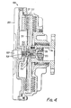
- the transmission unit comprises a rotary casing 10 formed from two casing members or shells 11, 12 and an internal rotary element 13 connected to a short hollow shaft 14 having an external flange 15 by which it may be bolted to the drive flange of a shaft, not shown, driven by the vehicle engine.
- the fan blades 16 are attached to a ring 17 secured to the casing shell 11 by bolts 18 with intervening resilient cushioning elements 20.
- the two casing shells 11, 12 are formed with internal annular grooves and ribs 23 and the rotary element 13 has corresponding grooves and ribs 24 which lie between and are closely spaced from the grooving and ribs 23 on the casing.
- annular wall 25 is provided within the casing defining an annular reservoir 26 and a radial passage 27 (closed at its radially outer end) leads inwards to this reservoir from a pumping port 28 which opens axially in an interior face 31 of the casing shell 12 and which cooperates with a scoop 29 (Figure 2) in this outer annular face of the casing.
- the scoop 29 is in the form of a flat strip of metal secured to the face 31 by a screw.
- the adjacent annular face 30 of the internal rotary element 13 creates a rotational movement of the fluid between the two parts and thus causes pumping action driving the fluid radially inwards.
- the effectiveness of the pumping action can be varied by altering the distance or displacement between the two faces 30, 31 and in this example, the control is effected by bodily axial movement of the whole rotary element 13 relative to the casing.
- An internal pneumatically operated ram includes a ram cylinder 35 connected via a thrust bearing 36 to the shaft 14 and thus held fixed axially.
- An annular piston 37 is connected by an internal hollow spindle 38 and another thrust bearing 39 to the forward casing part 12. Compressed air to operate the ram is admitted via a flexible pressure tube 40 and a coupling 41 to an internal passage 42 within the spindle 38, this communicating via port 43 with an annular space 44 between the piston and cylinder.
- Compressed air is automatically admitted to the pressure hose 40 under the control of a thermostat sensing the temperature of the coolant for the engine.
- a thermostat sensing the temperature of the coolant for the engine.
- the supply of compressed air is shut off by a valve (not shown) and a compression spring 45 acts in an axial direction urging the casing 12 bodily to the left in Figure 1 so as to cause axial separation between the surfaces 30, 31 and thus destroy the pumping action. Accordingly, fluid is retained in the whole labyrinth zone and the maximum viscous drive is obtained hence causing the maximum cooling effect of the fan blade 16.
- the thermostat When the sensed coolant temperature falls, the thermostat opens the air valve admitting compressed air to the hose 40 from which it is transmitted to the front face of the piston 37 generating an axial force which overcomes the spring 45 and causes the casing to move bodily to the right thus closing the clearance between the pumping faces 30 and 31.
- the resultant pumping action drives the fluid radially inwards along the passage 27 into the reservoir 26 where it is retained and the depletion of fluid in the labyrinth pumping zone causes the drive to be interrupted.
- the rotary element 13 may be provided with an additional ring 50 in close contact with the innermost rib 51 on the casing, and acting as a valve such that when the element 13 moves relatively to the right the rib 50 opens a small gap and allows fluid to flow back to the pumping zone. This again is provided without any other internal moving parts.
- the unit, as described, may be designed for a positive on/off operation, the internal element 13 having just two possible positions relative to the casing.
- the ram cylinder 35 and annular piston 37 may be arranged to control or adjust the relative axial position of the rotary element 13 so as to provide either continuous variation or stepping positioning so as to modify or modulate the pumping effect and hence to modulate the quantity of fluid in the labyrinth, which in turn provides modulation of the speed of the fan.
- ram 35 and piston 37 may be employed, for example, an electric solenoid, or a mechanical linkage, or a mechanical connection to a remote fluid actuator.
- the control is derived from a remote thermal sensor, not illustrated, positioned in the liquid coolant circuit of the engine.
- Other thermal controls may be used such as an air sensing unit, for example in a form of a bi-metal strip positioned in the air stream flowing over the fan blades 16.
- This bi-metal element may be located, for example, at the left-hand front end of the unit centrally on the rotary axis and arranged to operate a small pneumatic control valve which admits compressed air to the ram 35 and piston 37.
- the air sensing unit may be used as an alternative or an addition to the liquid coolant sensor as described.
- the variation in drive can be achieved automatically as a result of the change in temperature of a wax capsule which acts between axially movable parts of the drive comprising an external rotary casing and an internal rotary element.
- the rotary casing 100 includes a casing member or shell 120 formed with a central cavity 152 housing a compression spring 153 which reacts against an annular flange 154 on the end of a spindle 155 mounted with the shaft 14 via a thrust bearing 136.
- the spring 153 therefore, normally acts to cause the casing 100 to be biased to the right to close the clearance between the faces 130 and 131 with the resulting interruption of the drive.
- a wax capsule 156 within a cavity 157 in the spindle 155 expands and drives out a piston 158 on a plug 159 secured within the shell 120, thus overcoming the bias of the spring 153 and causing the casing 100 to move bodily to the left. This opens the clearance between the pumping faces 130 and 131 to reduce or destroy the pumping action so that the viscous drive between the casing 100 and the rotary element 113 is restored.
- bleed holes may be one or more bleed holes extending through the annular wall 25, for example close to its outer periphery, the size of the hole or holes being selected to achieve the desired idle speed and/or rate of fan engagement.
Landscapes
- Engineering & Computer Science (AREA)
- General Engineering & Computer Science (AREA)
- Mechanical Engineering (AREA)
- General Details Of Gearings (AREA)
Claims (8)
Priority Applications (1)
| Application Number | Priority Date | Filing Date | Title |
|---|---|---|---|
| AT86302616T ATE46749T1 (de) | 1985-04-09 | 1986-04-09 | Fluessigkeitsgetriebe. |
Applications Claiming Priority (4)
| Application Number | Priority Date | Filing Date | Title |
|---|---|---|---|
| GB8509041 | 1985-04-09 | ||
| GB858509041A GB8509041D0 (en) | 1985-04-09 | 1985-04-09 | Viscous fluid transmissions |
| GB8515790 | 1985-06-21 | ||
| GB858515790A GB8515790D0 (en) | 1985-04-09 | 1985-06-21 | Viscous fluid transmissions |
Publications (2)
| Publication Number | Publication Date |
|---|---|
| EP0197796A1 EP0197796A1 (de) | 1986-10-15 |
| EP0197796B1 true EP0197796B1 (de) | 1989-09-27 |
Family
ID=26289102
Family Applications (1)
| Application Number | Title | Priority Date | Filing Date |
|---|---|---|---|
| EP86302616A Expired EP0197796B1 (de) | 1985-04-09 | 1986-04-09 | Flüssigkeitsgetriebe |
Country Status (3)
| Country | Link |
|---|---|
| US (1) | US4682679A (de) |
| EP (1) | EP0197796B1 (de) |
| DE (1) | DE3665912D1 (de) |
Families Citing this family (7)
| Publication number | Priority date | Publication date | Assignee | Title |
|---|---|---|---|---|
| DE3807109A1 (de) * | 1988-03-04 | 1989-09-14 | Fichtel & Sachs Ag | Visco-luefterkupplung |
| US4917573A (en) * | 1989-05-31 | 1990-04-17 | Deere & Company | Cooling fan isolation mount |
| BE1004675A3 (fr) * | 1991-03-11 | 1993-01-12 | Solvay | Procede d'obtention de particules microspheroidales homodisperses, particules microspheroidales de silice a surface specifique elevee, catalyseurs supportes sur ces particules et procede de polymerisation des alpha-olefines en presence de ces catalyseurs. |
| JPH08296669A (ja) * | 1995-04-27 | 1996-11-12 | Usui Internatl Ind Co Ltd | 流体式ファン・カップリング装置 |
| DE19702973C2 (de) * | 1996-02-10 | 2002-03-07 | Behr Gmbh & Co | Flüssigkeitsreibungskupplung |
| DE19623676C1 (de) * | 1996-06-14 | 1997-07-03 | Fichtel & Sachs Ag | Klimaanlage mit einem Kältekompressor mit Visko-Kupplung |
| US8464963B2 (en) * | 2007-02-15 | 2013-06-18 | Borgwarner Inc. | Viscous coolant heater with variable coolant pump drive |
Family Cites Families (26)
| Publication number | Priority date | Publication date | Assignee | Title |
|---|---|---|---|---|
| US25481A (en) * | 1859-09-20 | Changeable stencil | ||
| USRE25481E (en) | 1963-11-12 | Fluid coupling mechanism | ||
| US2838244A (en) * | 1955-01-10 | 1958-06-10 | Eaton Mfg Co | Viscous drive for fan |
| US3055473A (en) * | 1959-05-11 | 1962-09-25 | Eaton Mfg Co | Fluid coupling device |
| US3101825A (en) * | 1959-09-10 | 1963-08-27 | Caroli Gerhard | Hydraulic clutch |
| DE1245655B (de) * | 1961-05-18 | 1967-07-27 | Eaton Yale & Towne | Fluessigkeitsreibungskupplung mit insbesondere temperaturabhaengig gesteuerter Fuellung |
| US3227254A (en) * | 1962-07-25 | 1966-01-04 | Eaton Mfg Co | Fluid coupling |
| US3191733A (en) * | 1963-01-07 | 1965-06-29 | Schwitzer Corp | Torque transmitting fluid coupling |
| US3194372A (en) * | 1963-03-06 | 1965-07-13 | Schwitzer Corp | Variable volume coupling mechanism |
| US3236346A (en) * | 1963-05-15 | 1966-02-22 | Eaton Mfg Co | Shear type fluid coupling |
| US3339688A (en) * | 1963-09-20 | 1967-09-05 | Eaton Yale & Towne | Coupling device |
| US3263783A (en) * | 1963-10-14 | 1966-08-02 | Eaton Yale & Towne | Viscous drive coupling |
| US3339689A (en) * | 1963-10-25 | 1967-09-05 | Eaton Yale & Towne | Temperature responsive fluid coupling device |
| US3250355A (en) * | 1963-12-16 | 1966-05-10 | Schwitzer Corp | Remote control fluid coupling |
| US3262528A (en) * | 1964-03-18 | 1966-07-26 | Schwitzer Corp | Variable fluid torque coupling |
| US3403764A (en) * | 1966-02-14 | 1968-10-01 | Eaton Yale & Towne | Fluid coupling |
| US3490686A (en) * | 1968-03-14 | 1970-01-20 | Wallace Murray Corp | Fan drive |
| GB1377476A (en) * | 1970-11-21 | 1974-12-18 | Dynair Ltd | Fan drives |
| US3739891A (en) * | 1972-03-13 | 1973-06-19 | Gen Motors Corp | Viscous fluid clutch |
| GB1568814A (en) * | 1975-10-10 | 1980-06-04 | Elmer A | Cooling fan drives for internal combustion engines |
| JPS5927452B2 (ja) * | 1978-11-16 | 1984-07-05 | アイシン精機株式会社 | 粘性流体継手装置 |
| US4282960A (en) * | 1979-06-08 | 1981-08-11 | Cummins Engine Company | Viscous fluid clutch |
| US4269295A (en) * | 1979-08-01 | 1981-05-26 | Murray Corporation | Torque transmitting fluid couplings |
| JPS57132026U (de) * | 1981-02-13 | 1982-08-17 | ||
| DE3122958A1 (de) * | 1981-06-10 | 1983-01-05 | Fichtel & Sachs Ag, 8720 Schweinfurt | Viskose-luefterkupplung mit rueckschlagventil |
| US4458798A (en) * | 1981-12-03 | 1984-07-10 | Eaton Corporation | Rotary magnetic control for a viscous fluid coupling |
-
1986
- 1986-03-03 US US06/835,732 patent/US4682679A/en not_active Expired - Fee Related
- 1986-04-09 EP EP86302616A patent/EP0197796B1/de not_active Expired
- 1986-04-09 DE DE8686302616T patent/DE3665912D1/de not_active Expired
Also Published As
| Publication number | Publication date |
|---|---|
| EP0197796A1 (de) | 1986-10-15 |
| DE3665912D1 (en) | 1989-11-02 |
| US4682679A (en) | 1987-07-28 |
Similar Documents
| Publication | Publication Date | Title |
|---|---|---|
| US3055473A (en) | Fluid coupling device | |
| US3191733A (en) | Torque transmitting fluid coupling | |
| EP2166246B1 (de) | Geteilter Vorratsbehälter einer Visko-Kupplung | |
| US3856122A (en) | Viscous coupling | |
| JPS597844B2 (ja) | 特に内燃機関の冷却フアンのための流体摩擦クラツチ | |
| US3262528A (en) | Variable fluid torque coupling | |
| KR920008643B1 (ko) | 온도감응식 팬 유체 커플링 | |
| US3972399A (en) | Temperature responsive coupling | |
| US2637308A (en) | Fan drive clutch | |
| US3250355A (en) | Remote control fluid coupling | |
| GB2163835A (en) | Viscous fluid couplings | |
| JPH0366536B2 (de) | ||
| US4898267A (en) | Electroviscous fluid clutch | |
| US3339689A (en) | Temperature responsive fluid coupling device | |
| EP0197796B1 (de) | Flüssigkeitsgetriebe | |
| CA1177712A (en) | Modulating fluid shear coupling | |
| US5152384A (en) | Viscous fluid coupling and remote control assembly therefor | |
| JPH0356328B2 (de) | ||
| JPS6034527A (ja) | 流体継手 | |
| EP0378341B1 (de) | Viskose Flüssigkeitsreibungskupplung und Regelventile dafür | |
| US3339688A (en) | Coupling device | |
| US5558192A (en) | Fluid coupling and external control therefor | |
| CA1299977C (en) | Viscous drive with variable pump action | |
| US6896191B2 (en) | Heating device suitable for motor vehicles | |
| US6029613A (en) | Viscous liquid heater |
Legal Events
| Date | Code | Title | Description |
|---|---|---|---|
| PUAI | Public reference made under article 153(3) epc to a published international application that has entered the european phase |
Free format text: ORIGINAL CODE: 0009012 |
|
| AK | Designated contracting states |
Kind code of ref document: A1 Designated state(s): AT BE CH DE FR GB IT LI NL SE |
|
| 17P | Request for examination filed |
Effective date: 19870414 |
|
| 17Q | First examination report despatched |
Effective date: 19880516 |
|
| ITF | It: translation for a ep patent filed | ||
| GRAA | (expected) grant |
Free format text: ORIGINAL CODE: 0009210 |
|
| AK | Designated contracting states |
Kind code of ref document: B1 Designated state(s): AT BE CH DE FR GB IT LI NL SE |
|
| REF | Corresponds to: |
Ref document number: 46749 Country of ref document: AT Date of ref document: 19891015 Kind code of ref document: T |
|
| REF | Corresponds to: |
Ref document number: 3665912 Country of ref document: DE Date of ref document: 19891102 |
|
| ET | Fr: translation filed | ||
| PLBE | No opposition filed within time limit |
Free format text: ORIGINAL CODE: 0009261 |
|
| STAA | Information on the status of an ep patent application or granted ep patent |
Free format text: STATUS: NO OPPOSITION FILED WITHIN TIME LIMIT |
|
| 26N | No opposition filed | ||
| PGFP | Annual fee paid to national office [announced via postgrant information from national office to epo] |
Ref country code: AT Payment date: 19910325 Year of fee payment: 6 |
|
| PGFP | Annual fee paid to national office [announced via postgrant information from national office to epo] |
Ref country code: SE Payment date: 19910328 Year of fee payment: 6 |
|
| PGFP | Annual fee paid to national office [announced via postgrant information from national office to epo] |
Ref country code: FR Payment date: 19910422 Year of fee payment: 6 |
|
| PGFP | Annual fee paid to national office [announced via postgrant information from national office to epo] |
Ref country code: NL Payment date: 19910430 Year of fee payment: 6 |
|
| PGFP | Annual fee paid to national office [announced via postgrant information from national office to epo] |
Ref country code: CH Payment date: 19910628 Year of fee payment: 6 |
|
| PGFP | Annual fee paid to national office [announced via postgrant information from national office to epo] |
Ref country code: BE Payment date: 19910712 Year of fee payment: 6 |
|
| PG25 | Lapsed in a contracting state [announced via postgrant information from national office to epo] |
Ref country code: AT Effective date: 19920409 |
|
| PG25 | Lapsed in a contracting state [announced via postgrant information from national office to epo] |
Ref country code: SE Effective date: 19920410 |
|
| PG25 | Lapsed in a contracting state [announced via postgrant information from national office to epo] |
Ref country code: LI Effective date: 19920430 Ref country code: CH Effective date: 19920430 Ref country code: BE Effective date: 19920430 |
|
| BERE | Be: lapsed |
Owner name: KYSOR INDUSTRIAL CORP. Effective date: 19920430 |
|
| PG25 | Lapsed in a contracting state [announced via postgrant information from national office to epo] |
Ref country code: NL Effective date: 19921101 |
|
| NLV4 | Nl: lapsed or anulled due to non-payment of the annual fee | ||
| PG25 | Lapsed in a contracting state [announced via postgrant information from national office to epo] |
Ref country code: FR Effective date: 19921230 |
|
| REG | Reference to a national code |
Ref country code: CH Ref legal event code: PL |
|
| REG | Reference to a national code |
Ref country code: FR Ref legal event code: ST |
|
| PGFP | Annual fee paid to national office [announced via postgrant information from national office to epo] |
Ref country code: GB Payment date: 19930319 Year of fee payment: 8 |
|
| PGFP | Annual fee paid to national office [announced via postgrant information from national office to epo] |
Ref country code: DE Payment date: 19930428 Year of fee payment: 8 |
|
| ITTA | It: last paid annual fee | ||
| PG25 | Lapsed in a contracting state [announced via postgrant information from national office to epo] |
Ref country code: GB Effective date: 19940409 |
|
| GBPC | Gb: european patent ceased through non-payment of renewal fee |
Effective date: 19940409 |
|
| PG25 | Lapsed in a contracting state [announced via postgrant information from national office to epo] |
Ref country code: DE Effective date: 19950103 |
|
| EUG | Se: european patent has lapsed |
Ref document number: 86302616.7 Effective date: 19921108 |
|
| PG25 | Lapsed in a contracting state [announced via postgrant information from national office to epo] |
Ref country code: IT Free format text: LAPSE BECAUSE OF NON-PAYMENT OF DUE FEES;WARNING: LAPSES OF ITALIAN PATENTS WITH EFFECTIVE DATE BEFORE 2007 MAY HAVE OCCURRED AT ANY TIME BEFORE 2007. THE CORRECT EFFECTIVE DATE MAY BE DIFFERENT FROM THE ONE RECORDED. Effective date: 20050409 |