EP0196846B1 - Méthode et appareil pour commander un moteur électrique à courant alternatif - Google Patents
Méthode et appareil pour commander un moteur électrique à courant alternatif Download PDFInfo
- Publication number
- EP0196846B1 EP0196846B1 EP86302131A EP86302131A EP0196846B1 EP 0196846 B1 EP0196846 B1 EP 0196846B1 EP 86302131 A EP86302131 A EP 86302131A EP 86302131 A EP86302131 A EP 86302131A EP 0196846 B1 EP0196846 B1 EP 0196846B1
- Authority
- EP
- European Patent Office
- Prior art keywords
- motor
- current
- voltage
- rated
- frequency
- Prior art date
- Legal status (The legal status is an assumption and is not a legal conclusion. Google has not performed a legal analysis and makes no representation as to the accuracy of the status listed.)
- Expired - Lifetime
Links
Images
Classifications
-
- H—ELECTRICITY
- H02—GENERATION; CONVERSION OR DISTRIBUTION OF ELECTRIC POWER
- H02P—CONTROL OR REGULATION OF ELECTRIC MOTORS, ELECTRIC GENERATORS OR DYNAMO-ELECTRIC CONVERTERS; CONTROLLING TRANSFORMERS, REACTORS OR CHOKE COILS
- H02P27/00—Arrangements or methods for the control of AC motors characterised by the kind of supply voltage
- H02P27/04—Arrangements or methods for the control of AC motors characterised by the kind of supply voltage using variable-frequency supply voltage, e.g. inverter or converter supply voltage
- H02P27/06—Arrangements or methods for the control of AC motors characterised by the kind of supply voltage using variable-frequency supply voltage, e.g. inverter or converter supply voltage using dc to ac converters or inverters
Definitions
- This invention relates to a method and apparatus for controlling the motor speed of an AC motor and a method of determining torque.
- Squirrel cage induction motors are often desirable motors for industrial applications because of their low cost, ready availability, ruggedness and reliability.
- the speed of the motor has not been easily controllable but is determined by the number of poles, the mains supply frequency, and the motor loading.
- the motor loading causes small deviations in speed known as the motor slip.
- Inverter drives for AC motors are now available at reasonable cost and allow the frequency of the voltage supplied to the motor to be varied over a wide range.
- the motor speed under no load conditions can be varied by adjusting the inverter output frequency, but small speed variations caused by changing motor loads are still present.
- To control the speed more accurately it is common practice to use a tachogenerator on the output shaft of the motor with a feedback control signal operating on the inverter output frequency.
- Another approach to providing a motor speed controller may be found in GB ⁇ A ⁇ 2075716 which discloses adjusting the AC voltage to the motor in dependence on the magnitude of the current signal.
- the invention consists in a method of controlling the motor speed of an electric AC motor comprising the steps of:
- the invention consists in a method according to the preceding paragraph defining the method of controlling motor speed further including the steps of determining torque by adjusting the AC motor terminal voltage and current until the proportion of the rated voltage and proportion of the rated current at a given frequency are equal, measuring the proportion of the rated voltage or current and squaring the read voltage or current to give the motor torque in proportion to its rated value.
- the input current I is given by since
- both the voltage and the current magnitude vary in exact proportion as the shaft torque varies for any given excitation frequency - this is in sharp contrast to the more usual mode of operation of an induction motor where the voltage is held constant and the torque increases as the current increases for the usual range of operating slip frequencies.
- a torque and speed control strategy is therefore to adjust the terminal voltage until the p.u. voltage (at that frequency) and the p.u. current are equal. At this precise point the p.u. torque is then given-by the square of the p.u. voltage (or current) while the slip frequency is the rated value for the machine so that the shaft speed is known directly from a knowledge of the inverter frequency.
- equation (14) For small variations about the steady state operating point we may differentiate equation (14) to leave at
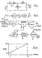
- a frequency input device a 1 p.u. voltage (which varies with frequency) calculation circuit
- an electronic multiplier an inverter with independent amplitude and frequency controls
- an induction motor with a current sensor and a current filter.
- the inverter simply performs the function of a high power amplifier and is assumed to have no effect on the p.u. values of the signals it passes.
- the inputs to the electronic multiplier are the 1 p.u. voltage according to equation (12) and the filtered signal representing the p.u. motor current.
- an input signal represents the required frequency to drive the motor 5.
- Adder 1 adds to this frequency input an offset voltage controllable by potentiometer 2 so that the output of adder 1 varies linearly with the frequency input but is displaced at zero frequency in such a way as to.follow the required voltage amplitudes versus frequency characteristics.
- the current from motor 5 is measured by a current sensor 6 which may be any one of a variety of current sensors well known to motor controller designers - for example it may use Hall-effect devices to measure the alternating current and then rectify this measured signal with a diode bridge to give a signal representative of the motor current amplitude.
- This current signal is then filtered by a low pass filter comprising resistor 7 and capacitor 8.
- inverter 4 which produces high voltage waveforms corresponding to those voltage and frequency signals to power motor 5.
- inverter 4 will be a pulse- width-modulated inverter which allows for rapid and easy changing of both the amplitude and frequency inputs.
- V b (cf. Fig. 4) is given by which is inconvenient to calculate ask,, R" and R 2 are difficult to determine.
- a simple setting up procedure is however possible involving the steps of
- the motor speed can be held essentially constant, as the motor torque varies over a wide range (from 0.05 to 1.0 p.u.) without the need for a tachogenerator.
- the motor torque can be determined in a simple fashion at any time while the motor speed is being so controlled. Motor losses are able to be significantly reduced at times when high voltage boost is not necessary and thus at any speed including stall or starting conditions the motor voltage is effectively varied dynamically in such a way that the speed is controlled, and the torque can be determined, yet the motor losses are only as high as those necessary to drive the connected load.
- the technique described in this invention is applicable to situations where the drive operation is essentially steady state or continuous such as pumps, fans and blowers, machine tools, and conveyors. It is not effective with pulsing tools where the pulsations occur in less than typically 0.5 seconds. Apart from this restraint, the invention is applicable to all types of inverter, converter, and cycloconverter drive to give improved efficiency, lower motor losses, speed control, and torque measurement, over a wide range of operating conditions, with no external flux, speed or other transducers.
Claims (10)


Priority Applications (1)
| Application Number | Priority Date | Filing Date | Title |
|---|---|---|---|
| AT86302131T ATE52886T1 (de) | 1985-03-21 | 1986-03-21 | Methode und geraet zum regeln eines elektrischen wechselstrommotors. |
Applications Claiming Priority (2)
| Application Number | Priority Date | Filing Date | Title |
|---|---|---|---|
| NZ211523 | 1985-03-21 | ||
| NZ211523A NZ211523A (en) | 1985-03-21 | 1985-03-21 | Motor speed control by frequency dependent signal |
Publications (2)
| Publication Number | Publication Date |
|---|---|
| EP0196846A1 EP0196846A1 (fr) | 1986-10-08 |
| EP0196846B1 true EP0196846B1 (fr) | 1990-05-16 |
Family
ID=19921140
Family Applications (1)
| Application Number | Title | Priority Date | Filing Date |
|---|---|---|---|
| EP86302131A Expired - Lifetime EP0196846B1 (fr) | 1985-03-21 | 1986-03-21 | Méthode et appareil pour commander un moteur électrique à courant alternatif |
Country Status (7)
| Country | Link |
|---|---|
| US (1) | US4881022A (fr) |
| EP (1) | EP0196846B1 (fr) |
| AT (1) | ATE52886T1 (fr) |
| AU (1) | AU594667B2 (fr) |
| CA (1) | CA1288464C (fr) |
| DE (1) | DE3671345D1 (fr) |
| NZ (1) | NZ211523A (fr) |
Families Citing this family (11)
| Publication number | Priority date | Publication date | Assignee | Title |
|---|---|---|---|---|
| NZ211523A (en) * | 1985-03-21 | 1990-03-27 | Univ Auckland | Motor speed control by frequency dependent signal |
| FI981186A (fi) * | 1998-05-28 | 1999-11-29 | Stenman Ulf Haakan | Uusi immunomääritys ja sen käyttö diagnostiikassa |
| US20030070544A1 (en) * | 2001-10-15 | 2003-04-17 | Hamilton Beach/Proctor-Silex, Inc. | System and method for determining filter condition |
| EP1501186B1 (fr) * | 2003-07-18 | 2018-08-22 | III Holdings 10, LLC | Appareil de commande de moteur |
| EP1607563A1 (fr) * | 2004-05-28 | 2005-12-21 | Cardo Door Ab | Dispositif d'entrainement et procede pour une porte avec regulation de temperature de la transmission |
| US20070024224A1 (en) * | 2005-07-26 | 2007-02-01 | Mcdonald Raymond G | kW-based torque control for AC motors |
| NZ545664A (en) * | 2006-02-28 | 2008-07-31 | Auckland Uniservices Ltd | Single phase power supply for inductively coupled power transfer systems |
| GB2530293B (en) * | 2014-09-17 | 2017-08-02 | Nidec Control Techniques Ltd | Method of controlling a power output of an inverter drive |
| US11207988B2 (en) | 2018-08-06 | 2021-12-28 | Robert M. Lyden | Electric or hybrid vehicle with wireless device and method of supplying electromagnetic energy to vehicle |
| US10840707B2 (en) | 2018-08-06 | 2020-11-17 | Robert M. Lyden | Utility pole with solar modules and wireless device and method of retrofitting existing utility pole |
| US11588421B1 (en) | 2019-08-15 | 2023-02-21 | Robert M. Lyden | Receiver device of energy from the earth and its atmosphere |
Family Cites Families (5)
| Publication number | Priority date | Publication date | Assignee | Title |
|---|---|---|---|---|
| DE2361339C3 (de) * | 1973-12-08 | 1985-05-30 | Brown, Boveri & Cie Ag, 6800 Mannheim | Anordnung zur Steuerung des Drehmomentes einer Asynchronmaschine |
| US3909687A (en) * | 1974-03-05 | 1975-09-30 | Westinghouse Electric Corp | Flux control system for controlled induction motors |
| US3989991A (en) * | 1974-10-03 | 1976-11-02 | Westinghouse Electric Corporation | Method and circuit for the derivation of an analog slip frequency signal of an induction motor in a tachometerless motor drive |
| US4443750A (en) * | 1980-04-30 | 1984-04-17 | Zero-Max Industries, Incorporated | Energy saving motor speed controller |
| NZ211523A (en) * | 1985-03-21 | 1990-03-27 | Univ Auckland | Motor speed control by frequency dependent signal |
-
1985
- 1985-03-21 NZ NZ211523A patent/NZ211523A/xx unknown
-
1986
- 1986-03-20 AU AU54965/86A patent/AU594667B2/en not_active Ceased
- 1986-03-21 DE DE8686302131T patent/DE3671345D1/de not_active Expired - Lifetime
- 1986-03-21 CA CA000504782A patent/CA1288464C/fr not_active Expired - Lifetime
- 1986-03-21 AT AT86302131T patent/ATE52886T1/de not_active IP Right Cessation
- 1986-03-21 EP EP86302131A patent/EP0196846B1/fr not_active Expired - Lifetime
-
1988
- 1988-05-10 US US07/191,711 patent/US4881022A/en not_active Expired - Fee Related
Also Published As
| Publication number | Publication date |
|---|---|
| ATE52886T1 (de) | 1990-06-15 |
| AU594667B2 (en) | 1990-03-15 |
| CA1288464C (fr) | 1991-09-03 |
| AU5496586A (en) | 1986-09-25 |
| DE3671345D1 (de) | 1990-06-21 |
| US4881022A (en) | 1989-11-14 |
| EP0196846A1 (fr) | 1986-10-08 |
| NZ211523A (en) | 1990-03-27 |
Similar Documents
| Publication | Publication Date | Title |
|---|---|---|
| US5440219A (en) | Induction motor speed control having improved sensing of motor operative conditions | |
| US5689169A (en) | Transient inductance identifier for motor control | |
| US4041361A (en) | Constant torque induction motor drive system | |
| US20060066275A1 (en) | Method and apparatus to regulate torque provided to loads | |
| EP0196846B1 (fr) | Méthode et appareil pour commander un moteur électrique à courant alternatif | |
| WO1995028031A1 (fr) | Procede et appareil de regulation de moteurs a induction | |
| EP0279415A1 (fr) | Appareil de régulation pour un moteur à induction | |
| KR900001961B1 (ko) | 엘리베이터의 속도 제어장치 | |
| US6528966B2 (en) | Sensorless vector control apparatus and method thereof | |
| CN100359798C (zh) | 控制双输送机的方法 | |
| KR0134984B1 (ko) | 모우터 제어 장치 | |
| SU1435164A3 (ru) | Устройство дл регулировани частоты вращени и крут щего момента асинхронного двигател | |
| EP3171508A1 (fr) | Procédé pour la commande de scalaire d'un moteur à induction, en particulier au fonctionnement à faible vitesse, et système de commande scalaire destiné à un moteur à induction | |
| US4322672A (en) | Electric motor control apparatus | |
| US11404982B2 (en) | Method for estimating mechanical parameters of an electrical motor | |
| JPS633556B2 (fr) | ||
| Venkataraman et al. | Electronic analog slip calculator for induction motor drives | |
| RU2380821C2 (ru) | Электропривод переменного тока | |
| RU2389127C2 (ru) | Электропривод переменного тока | |
| RU2251204C1 (ru) | Электропривод переменного тока | |
| Jerkovic et al. | Comparison of different motor control principles using frequency converter | |
| SU1737694A1 (ru) | Электропривод переменного тока | |
| RU2123757C1 (ru) | Устройство управления асинхронным тяговым электродвигателем | |
| SU936321A1 (ru) | Устройство дл измерени статического момента нагрузки электропривода посто нного тока | |
| JPH0683597B2 (ja) | リラクタンス発電機制御装置 |
Legal Events
| Date | Code | Title | Description |
|---|---|---|---|
| PUAI | Public reference made under article 153(3) epc to a published international application that has entered the european phase |
Free format text: ORIGINAL CODE: 0009012 |
|
| AK | Designated contracting states |
Kind code of ref document: A1 Designated state(s): AT BE CH DE FR GB IT LI LU NL SE |
|
| 17P | Request for examination filed |
Effective date: 19870116 |
|
| 17Q | First examination report despatched |
Effective date: 19880519 |
|
| GRAA | (expected) grant |
Free format text: ORIGINAL CODE: 0009210 |
|
| AK | Designated contracting states |
Kind code of ref document: B1 Designated state(s): AT BE CH DE FR GB IT LI LU NL SE |
|
| PG25 | Lapsed in a contracting state [announced via postgrant information from national office to epo] |
Ref country code: SE Effective date: 19900516 Ref country code: NL Effective date: 19900516 Ref country code: LI Effective date: 19900516 Ref country code: CH Effective date: 19900516 Ref country code: BE Effective date: 19900516 Ref country code: AT Effective date: 19900516 |
|
| REF | Corresponds to: |
Ref document number: 52886 Country of ref document: AT Date of ref document: 19900615 Kind code of ref document: T |
|
| ITF | It: translation for a ep patent filed |
Owner name: JACOBACCI & PERANI S.P.A. |
|
| REF | Corresponds to: |
Ref document number: 3671345 Country of ref document: DE Date of ref document: 19900621 |
|
| ET | Fr: translation filed | ||
| REG | Reference to a national code |
Ref country code: CH Ref legal event code: PL |
|
| NLV1 | Nl: lapsed or annulled due to failure to fulfill the requirements of art. 29p and 29m of the patents act | ||
| PLBE | No opposition filed within time limit |
Free format text: ORIGINAL CODE: 0009261 |
|
| STAA | Information on the status of an ep patent application or granted ep patent |
Free format text: STATUS: NO OPPOSITION FILED WITHIN TIME LIMIT |
|
| PG25 | Lapsed in a contracting state [announced via postgrant information from national office to epo] |
Ref country code: LU Free format text: LAPSE BECAUSE OF NON-PAYMENT OF DUE FEES Effective date: 19910331 |
|
| 26N | No opposition filed | ||
| ITTA | It: last paid annual fee | ||
| PGFP | Annual fee paid to national office [announced via postgrant information from national office to epo] |
Ref country code: FR Payment date: 19931215 Year of fee payment: 9 |
|
| PGFP | Annual fee paid to national office [announced via postgrant information from national office to epo] |
Ref country code: GB Payment date: 19931223 Year of fee payment: 9 |
|
| PGFP | Annual fee paid to national office [announced via postgrant information from national office to epo] |
Ref country code: DE Payment date: 19940525 Year of fee payment: 9 |
|
| PG25 | Lapsed in a contracting state [announced via postgrant information from national office to epo] |
Ref country code: GB Effective date: 19950321 |
|
| GBPC | Gb: european patent ceased through non-payment of renewal fee |
Effective date: 19950321 |
|
| PG25 | Lapsed in a contracting state [announced via postgrant information from national office to epo] |
Ref country code: FR Free format text: LAPSE BECAUSE OF NON-PAYMENT OF DUE FEES Effective date: 19951130 |
|
| PG25 | Lapsed in a contracting state [announced via postgrant information from national office to epo] |
Ref country code: DE Effective date: 19951201 |
|
| REG | Reference to a national code |
Ref country code: FR Ref legal event code: ST |
|
| PG25 | Lapsed in a contracting state [announced via postgrant information from national office to epo] |
Ref country code: IT Free format text: LAPSE BECAUSE OF NON-PAYMENT OF DUE FEES;WARNING: LAPSES OF ITALIAN PATENTS WITH EFFECTIVE DATE BEFORE 2007 MAY HAVE OCCURRED AT ANY TIME BEFORE 2007. THE CORRECT EFFECTIVE DATE MAY BE DIFFERENT FROM THE ONE RECORDED. Effective date: 20050321 |