EP0196817A1 - Dispositif de rattrapage automatique - Google Patents
Dispositif de rattrapage automatique Download PDFInfo
- Publication number
- EP0196817A1 EP0196817A1 EP86301915A EP86301915A EP0196817A1 EP 0196817 A1 EP0196817 A1 EP 0196817A1 EP 86301915 A EP86301915 A EP 86301915A EP 86301915 A EP86301915 A EP 86301915A EP 0196817 A1 EP0196817 A1 EP 0196817A1
- Authority
- EP
- European Patent Office
- Prior art keywords
- adjuster
- uni
- spindle
- rotation
- bore
- Prior art date
- Legal status (The legal status is an assumption and is not a legal conclusion. Google has not performed a legal analysis and makes no representation as to the accuracy of the status listed.)
- Granted
Links
Images


Classifications
-
- F—MECHANICAL ENGINEERING; LIGHTING; HEATING; WEAPONS; BLASTING
- F16—ENGINEERING ELEMENTS AND UNITS; GENERAL MEASURES FOR PRODUCING AND MAINTAINING EFFECTIVE FUNCTIONING OF MACHINES OR INSTALLATIONS; THERMAL INSULATION IN GENERAL
- F16D—COUPLINGS FOR TRANSMITTING ROTATION; CLUTCHES; BRAKES
- F16D65/00—Parts or details
- F16D65/38—Slack adjusters
- F16D65/40—Slack adjusters mechanical
- F16D65/52—Slack adjusters mechanical self-acting in one direction for adjusting excessive play
- F16D65/56—Slack adjusters mechanical self-acting in one direction for adjusting excessive play with screw-thread and nut
- F16D65/561—Slack adjusters mechanical self-acting in one direction for adjusting excessive play with screw-thread and nut for mounting within the confines of a drum brake
- F16D65/562—Slack adjusters mechanical self-acting in one direction for adjusting excessive play with screw-thread and nut for mounting within the confines of a drum brake arranged between service brake actuator and braking member, and subjected to service brake force
-
- F—MECHANICAL ENGINEERING; LIGHTING; HEATING; WEAPONS; BLASTING
- F16—ENGINEERING ELEMENTS AND UNITS; GENERAL MEASURES FOR PRODUCING AND MAINTAINING EFFECTIVE FUNCTIONING OF MACHINES OR INSTALLATIONS; THERMAL INSULATION IN GENERAL
- F16D—COUPLINGS FOR TRANSMITTING ROTATION; CLUTCHES; BRAKES
- F16D65/00—Parts or details
- F16D65/38—Slack adjusters
- F16D65/40—Slack adjusters mechanical
- F16D65/42—Slack adjusters mechanical non-automatic
- F16D65/46—Slack adjusters mechanical non-automatic with screw-thread and nut
-
- F—MECHANICAL ENGINEERING; LIGHTING; HEATING; WEAPONS; BLASTING
- F16—ENGINEERING ELEMENTS AND UNITS; GENERAL MEASURES FOR PRODUCING AND MAINTAINING EFFECTIVE FUNCTIONING OF MACHINES OR INSTALLATIONS; THERMAL INSULATION IN GENERAL
- F16D—COUPLINGS FOR TRANSMITTING ROTATION; CLUTCHES; BRAKES
- F16D2125/00—Components of actuators
- F16D2125/18—Mechanical mechanisms
- F16D2125/20—Mechanical mechanisms converting rotation to linear movement or vice versa
- F16D2125/22—Mechanical mechanisms converting rotation to linear movement or vice versa acting transversely to the axis of rotation
- F16D2125/26—Cranks
-
- F—MECHANICAL ENGINEERING; LIGHTING; HEATING; WEAPONS; BLASTING
- F16—ENGINEERING ELEMENTS AND UNITS; GENERAL MEASURES FOR PRODUCING AND MAINTAINING EFFECTIVE FUNCTIONING OF MACHINES OR INSTALLATIONS; THERMAL INSULATION IN GENERAL
- F16D—COUPLINGS FOR TRANSMITTING ROTATION; CLUTCHES; BRAKES
- F16D2125/00—Components of actuators
- F16D2125/18—Mechanical mechanisms
- F16D2125/20—Mechanical mechanisms converting rotation to linear movement or vice versa
- F16D2125/22—Mechanical mechanisms converting rotation to linear movement or vice versa acting transversely to the axis of rotation
- F16D2125/28—Cams; Levers with cams
- F16D2125/30—Cams; Levers with cams acting on two or more cam followers, e.g. S-cams
Definitions
- This invention relates to an automatic adjuster, primarily for a vehicle brake, operable to maintain a substantially constant clearance between the braking surfaces respectively of a braking element and a rotatable braking member of the brake, the adjuster being of the kind comprising a strut having two parts between which there is a non-reversible screw threaded connection permitting the effective length of the strut to be increased by relative rotation between the parts under the influence of an adjuster device which incorporates clutch means for controlling said relative rotation in response to the occurrence of excessive clearance between said surfaces.
- adjuster of this kind is illustrated in our earlier British Patent No.1419254 applied to a shoe drum brake, and incorporates a clutch member which is urged by resilient means into engagement with a clutch face so as normally to prevent rotation of an adjuster member. Whilst this arrangement operates quite satisfactorily under most conditions there can be a tendency, under heavy vibration for example, for the clutching force to be overcome temporarily, permitting the adjuster member to rotate to a de-adjusted position, giving rise to suddenly increased pedal movement upon brake actuation, and consequent adverse driver reaction.
- An object of the present invention is to provide an automatic adjuster in which the aforesaid tendency to random de-adjustment is minimised or avoided.
- an automatic adjuster comprises a strut having two parts between which there is a non-reversible screw threaded connection permitting the effective length of the strut to be increased by relative rotation between the parts under the influence of an adjuster device which incorporates clutch means for controlling said relative rotation in response to the occurrence of excessive clearance between braking surfaces, one of the adjuster parts being coupled by uni-directional means to a relatively fixed part of the adjuster to resist rotation of said one adjuster part in a de-adjusting direction but to permit rotation thereof in the adjusting direction.
- resilient means which urges the clutch into engagement acts also to urge the uni-directional means towards an operative condition.
- said uni-directional. means comprises two parts independently movable axially but keyed against relative rotation, one of which parts is non-rotatably engaged with said one adjuster part and the other of which is releasably uni-directionally coupled to said relatively fixed part.
- Said uni-directional means preferably includes a pawl engagable with a ratchet on said relatively fixed part.
- the ratchet may be of annular form and the uni-directional means may have angularly spaced arms, each carrying a pawl for engagement with the ratchet.
- the shoe drum brake illustrated therein has a pair of arcuate shoes 1 and 2 mounted on a backplate 3, each shoe having a friction lining 4 for braking engagement with a rotatable drum (not shown).
- the brake is of the leading/trailing type, having a cam actuator 5 mounted on the backplate 3 between one pair of adjacent shoe ends and an abutment device 6 also mounted on the backplate and disposed between the other pair of adjacent shoe ends, in conventional manner.
- the actuator 5 is illustrated in more detail in Figure 2 and will be seen to comprise a housing 7 adapted to be fixed in conventional manner to the backplate 3 and within which is mounted a rotary cam 8 which co-operates via struts 9 and inserts 10 with respective tappets indicated generally at 11, 12 the inserts being press-fitted within the tappets.
- Each tappet 11, 12 incorporates an automatic adjuster mechanism, each of which includes an internally threaded nut 13 through which extends'a correspondingly threaded spigot 14 projecting from a head portion 15 of the tappet, the nut and spigot together constituting a strut of variable length operable to alter the retracted position of the adjacent brake shoe in response to wear of the shoe friction lining.
- the adjacent shoe contacts the nut 13 and thereby prevents rotation of the nut which, however, may move axially along the spigot 14 by rotation of the latter.
- the external surface of the head 15 is formed with helical gear teeth 16 which mesh with similar teeth 17 on an end portion of an adjuster member in the form of a spigot 18 mounted in the housing for rotation about an axis at right angles to that of the tappet 11.
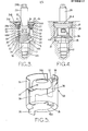
- the adjuster member and its associated mechanism is illustrated in more detail in Figures 3 and 4.
- the spigot 18 is mounted in a bore 19 of the housing which is stepped to receive various parts of the adjuster member and its associated mechanism which have different diameters.
- the spigot 18 is journalled for rotation in the bore by means respectively of larger and smaller diameter axially spaced portions 18A and 18B of the spigot.
- the helical teeth 25 are provided around the spigot adjacent the portion 18B and mesh with the teeth 16 of the head 15, as described above.
- the larger diameter portion 18A of the spigot terminates in a radial flange 20 and a clutch member 21 is pressed on to the portion 18A into abutment with the flange 20 in such a manner as to be rotatable with the spigot 18.
- the portion 18A is knurled so as to ensure keying of the clutch member to the spigot.
- the clutch member 21 is provided with a conical clutch face 22 which normally co-operates with a corresponding conical clutch surface 23 formed on the internal wall of the housing.
- the upper end of the bore 19 is closed by an end member 24 retained in position by a circlip 25 lodged under a shoulder 26 of the housing, and held against rotation by suitable means shown as a pair of opposed lugs 24A engaged in recesses 24B of the housing, although more or less than two could be used, as required.
- a seal 27 is interposed between the outer wall of an annular boss 28 of the end member and the inner wall of the bore to prevent ingress of foreign material.
- a manual adjuster spindle 29 is rotatably mounted in the end member and slidable longitudinally so that a hexagonal or similar formation 30 on the upper end of the adjuster member 18 may be engaged by a complementary recess in the inner end of the shaft 29 to enable manual adjustment of the adjuster to be effected by rotation of the shaft. Sealing between the shaft 29 and end member 24 is performed by a seal 31 interposed between an end surface of the end member and a rib 32 on the shaft.
- the adjuster of the invention is provided with a uni-directional coupling means, indicated generally at 33 which acts to prevent rotation of the spigot 18 in the de-adjusting direction.
- the coupling means includes a first component 34 in the form of a hollow can made from thin gauge metal and having a pair of tongues 35 projecting from its end which will be lowermost in use.
- the can is assembled around the upper end of the spigot 18 with the tongues 35 engaged closely within slots 36 formed in the upper surface of the larger diameter portion 19 of the spigot.
- the coupling means is thereby rendered substantially non-rotational relative to the spigot.
- a second component 33A of the coupling means is generally annular and, in use, surrounds the lower end portion of the manual adjuster shaft 29.
- a pair of arms 37 projecting radially from this component are engaged in respective longitudinal slots 38 of the first component to render the two components relatively non-rotatable but to allow relative axial movement between the two. Any other convenient number of arms may be used, as required.
- Each arm 37 is provided with an upstanding tongue 39 inclined to the upper surface of its associated arm and each forming a pawl for engagement with ratchet teeth 40 formed around the periphery of the lower end surface of the annular boss 28 of the end member 24, as will be seen more clearly from Figure 4.
- the pawls 39 are urged firmly into engagement with the teeth 40 by a spring 40A which acts between the flange 35A of the can 34 and component 33A.
- the direction of the ratchet action between the pawls 39 and teeth 40 is such that rotation of the adjuster member 18 in the de-adjusting direction is normally prevented, although the adjuster member is able to rotate in the opposite direction in order to permit operation of the automatic adjuster, in the manner now to be described.
- the tappets 11, 12 are urged outwardly in order to urge the shoes 1 and 2 into braking engagement with the brake drum.
- a predetermined amount of backlash is provided between the teeth 16 and 17 respectively on the tappet head portion 15 and adjuster member or spigot 18 to -permit the shoes to move outwardly sufficiently to take up the maximum desired shoe to drum clearance without causing operation of the automatic adjuster.
- wear of the friction linings 4 becomes such that the shoe movement exceeds this maximum clearance, the flanks of the teeth 15 and 18 come into engagement in such a manner as to lift the spigot 18 and thereby cause the clutch 21 to be disengaged from the seat 23, permitting rotation of the spigot 18 to occur dependent upon the amount of shoe outward movement.
- the coupling means rotates with the adjuster member, the second component 33A of the coupling means moving axially inwardly against the action of the spring 40A to permit the teeth 39 to move past a sufficient number of ratchet teeth 40 to accommodate such rotation.
- the brake shoes move inwardly under the action of the shoe return means, the backlash between the teeth 16 and 17 is taken up in the opposite direction, permitting the clutch 21 to re-engage the seat 23, whereupon the tappet 11, 12 rotates by inter-action between said teeth in a direction such as to lengthen the adjuster strut and thereby set a new retracted position for the associated shoe.
- the manual adjuster shaft 29 is normally urged in a direction away from the spigot 18 by a resilient element such as a Belleville washer 29A disposed between the rib 32 and the component 33A of the coupling means.
- the Belleville washer also serves to press the rib 32 firmly against the seal '3 1.
- the manual adjuster shaft 29 is urged axially inwardly against the action of the spring 40A to engage the socket in the inner end of the shaft 29 with the hexagonal formation 30 at the upper end of the spigot.
- This action will also move the second component 33A of the coupling means inwardly to disengage the pawls 39 from the ratchet teeth 40, leaving the adjuster shaft free to rotate in the de-adjustment direction by rotation of the shaft 29, which may conveniently be effected by applying a suitable tool to a further hexagonal formation 29 B at the outer end of the shaft 29.
- the component 33A is moved under the action of the spring 40A to re-engage the pawls 39 with the teeth 40 so as once again to lock the adjuster shaft 18 against unwanted movement in the de-adjustment direction.
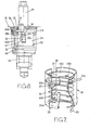
- FIGs 6 and 7 illustrate an alternative embodiment of the adjuster of the invention which is essentially similar to that of Figures 3 to 5, but includes a number of practical refinements.
- the uni-directional coupling means 33 is made as a self-contained unit by retaining the annular part 33A beneath pressed projections 33B extending inwardly of the internal wall of the can 34, the part 33A being urged against the projections by a spring 40A acting between that part and an inwardly directed flange 35A of the can.
- the can assembly is arranged around the upper end portion of the spigot 18, as before, with tongues 35 of the can closely engaging within slots 36 of the spigot.
- the annular part 33A is provided with three equi-angularly spaced arms 37 located in respective slots 38 of the .
- a further coil spring,41 acts between the flange 35A of the can and a flange 32 of the spindle 29, serving to urge the spindle towards its inoperative position and also to compress a seal 31 against the end cap 24 to prevent the ingress of foreign material around the spindle.
- the separate two-piece coupling means 33 is dispensed with and the spring 40A is arranged to perform the coupling function.
- the end member 24 is snap-engaged or otherwise non-rotatably retained in the housing and is provided with a pair of inwardly projecting pips 41 over an upper portion of its axial length which engage in opposed indents 42 formed in a flange 43 of the manual adjuster shaft 29.
- one or more axially extending pins carried by the end member 24 may engage in a corresponding number of slots in the flange 43. Seals 29 C and 24A respectively prevent ingress of foreign material between the shaft 29 and end member 24 and between the latter and the housing.
- the shaft 29 is urged by the spring 40A towards its position as shown in which it is disengaged from the adjuster shaft 18 and held against rotation by the pips 41.
- the lower end of the spring 40A is bent downwardly to form a detent 40B which engages in a recess 40C formed in the flange 20 of the adjuster shaft or spigot 18.
- the upper end of the spring is bent to provide an inclined portion 40 D which acts as a pawl engaging one of a number of ratchet teeth 43A formed on the underside of the flange 43 of the manual adjuster shaft 29.
- the spring 40A is therefore able to act as a uni-directional coupling means between the spigot 18 and manual adjuster shaft 29, the pawl 40D effectively preventing rotation of the spigot 18 in a de-adjusting direction by engagement with the normally non-rotatable shaft 29.
- Movememt of the adjuster shaft 18 in the adjusting direction is, however, permitted by the pawl 40D deforming resiliently to ride over the ratchet teeth 43A during operation of the automatic adjuster. Such operation is substantially as described in relation to the previous embodiment.
- the teeth'43A may be dispensed with and the pawl 40D may then co-operate with a series of radial slots formed in the flange periphery.
- the shaft 29 When manual adjustment is required, the shaft 29 is urged axially inwardly against the action of the spring 40A until the flange 43 has moved sufficiently inwardly to clear the pips 41, whereupon the shaft 29 may be rotated in the appropriate direction to effect corresponding rotation of the adjuster shaft 18 in the de-adjusting direction.
- the invention provides a simple and effective means for preventing any tendency of the adjuster member towards random de-adjustment caused, for example, by vibration, such means being arranged so as to be readily de-activated to enable manual adjustment of the brake to be effected by means of the manual adjuster shaft 29.
Landscapes
- Engineering & Computer Science (AREA)
- General Engineering & Computer Science (AREA)
- Mechanical Engineering (AREA)
- Braking Arrangements (AREA)
- Mechanical Operated Clutches (AREA)
Applications Claiming Priority (2)
| Application Number | Priority Date | Filing Date | Title |
|---|---|---|---|
| GB8507299 | 1985-03-21 | ||
| GB858507299A GB8507299D0 (en) | 1985-03-21 | 1985-03-21 | Automatic adjuster |
Publications (2)
| Publication Number | Publication Date |
|---|---|
| EP0196817A1 true EP0196817A1 (fr) | 1986-10-08 |
| EP0196817B1 EP0196817B1 (fr) | 1990-02-07 |
Family
ID=10576351
Family Applications (1)
| Application Number | Title | Priority Date | Filing Date |
|---|---|---|---|
| EP86301915A Expired EP0196817B1 (fr) | 1985-03-21 | 1986-03-17 | Dispositif de rattrapage automatique |
Country Status (9)
| Country | Link |
|---|---|
| US (1) | US4702352A (fr) |
| EP (1) | EP0196817B1 (fr) |
| JP (1) | JPS61252926A (fr) |
| BR (1) | BR8601238A (fr) |
| DE (1) | DE3668961D1 (fr) |
| ES (1) | ES8701934A1 (fr) |
| GB (1) | GB8507299D0 (fr) |
| HU (1) | HUT50709A (fr) |
| IN (1) | IN167241B (fr) |
Cited By (4)
| Publication number | Priority date | Publication date | Assignee | Title |
|---|---|---|---|---|
| EP0471496A1 (fr) * | 1990-08-14 | 1992-02-19 | Lucas Industries Public Limited Company | Ajusteur automatique pour freins |
| TR25633A (tr) * | 1990-08-14 | 1993-07-01 | Lucas Ind Plc | OTOMATIK FREN AN TESISATI ICIN KORUYUCU DEVRE VE KTELEKOMüNIKASYON TESISATI ICIN KORUYUCU DEVRE VE KORUYUCU FIS. ORUYUCU FIS. |
| GB2294739A (en) * | 1994-11-04 | 1996-05-08 | Lucas Ind Plc | An automatic brake shoe adjuster |
| WO2019025649A1 (fr) | 2017-07-29 | 2019-02-07 | Basamento De Alquileres, S.L. | Cuvette de toilettes comprenant un support de pieds pour une utilisation polyvalente |
Families Citing this family (7)
| Publication number | Priority date | Publication date | Assignee | Title |
|---|---|---|---|---|
| GB8916047D0 (en) * | 1989-07-13 | 1989-08-31 | Lucas Ind Plc | Brake actuator with adjuster |
| US5531298A (en) * | 1995-03-27 | 1996-07-02 | General Motors Corporation | Brake actuator |
| US6253890B1 (en) | 1999-06-17 | 2001-07-03 | Marc Hunter | Air brakes for trucks |
| WO2012125726A1 (fr) * | 2011-03-14 | 2012-09-20 | Intelligent Technologies International, Inc. | Système et procédé de prévention de vol de marchandises |
| US8835104B2 (en) | 2007-12-20 | 2014-09-16 | Fenwal, Inc. | Medium and methods for the storage of platelets |
| WO2012139017A1 (fr) | 2011-04-07 | 2012-10-11 | Fenwal, Inc. | Procédés et systèmes automatisés pour produire des concentrés de plaquettes avec des volumes de plasma résiduel réduits et des milieux de conservation pour de tels concentrés de plaquettes |
| CN112572679B (zh) * | 2020-12-16 | 2022-05-10 | 摩拜(北京)信息技术有限公司 | 刹车装置和共享车辆 |
Citations (7)
| Publication number | Priority date | Publication date | Assignee | Title |
|---|---|---|---|---|
| GB487461A (en) * | 1937-04-07 | 1938-06-21 | Bromsregulator Svenska Ab | Improvements in automatic slack adjusters for vehicle brakes, especially railway carbrakes |
| GB1179235A (en) * | 1966-03-18 | 1970-01-28 | Girling Ltd | Improvements in Brake Adjusters. |
| FR2048875A5 (fr) * | 1969-05-28 | 1971-03-19 | Perrot Bremse Gmbh Deutsche | |
| GB1419254A (en) * | 1972-12-07 | 1975-12-24 | Girling Ltd | Textensible strut assemblies |
| DE2647353A1 (de) * | 1975-10-20 | 1977-04-28 | Tokico Ltd | Mechanische scheibenbremse |
| FR2452020A1 (fr) * | 1979-03-20 | 1980-10-17 | Sab | Dispositif de blocage pour une piece soumise a un couple de rotation intempestif |
| EP0027352A1 (fr) * | 1979-10-10 | 1981-04-22 | LUCAS INDUSTRIES public limited company | Dispositifs de rattrapage automatique de jeu pour freins de véhicule à patin-tambour |
Family Cites Families (3)
| Publication number | Priority date | Publication date | Assignee | Title |
|---|---|---|---|---|
| US3882974A (en) * | 1973-01-23 | 1975-05-13 | Girling Ltd | Automatic slack adjuster for a vehicle brake |
| CA1201984A (fr) * | 1982-06-14 | 1986-03-18 | Sven E. Camph | Mecanisme de reprise automatique des jeux |
| US4530424A (en) * | 1982-09-30 | 1985-07-23 | Nisshin Kogyo Kabushiki Kaisha | Automatic braking-gap adjuster system for hydraulic brake |
-
1985
- 1985-03-21 GB GB858507299A patent/GB8507299D0/en active Pending
-
1986
- 1986-03-17 EP EP86301915A patent/EP0196817B1/fr not_active Expired
- 1986-03-17 DE DE8686301915T patent/DE3668961D1/de not_active Expired - Lifetime
- 1986-03-20 JP JP61063870A patent/JPS61252926A/ja active Pending
- 1986-03-20 BR BR8601238A patent/BR8601238A/pt unknown
- 1986-03-20 US US06/841,764 patent/US4702352A/en not_active Expired - Fee Related
- 1986-03-20 IN IN203/MAS/86A patent/IN167241B/en unknown
- 1986-03-20 ES ES553194A patent/ES8701934A1/es not_active Expired
- 1986-03-21 HU HU861203A patent/HUT50709A/hu unknown
Patent Citations (7)
| Publication number | Priority date | Publication date | Assignee | Title |
|---|---|---|---|---|
| GB487461A (en) * | 1937-04-07 | 1938-06-21 | Bromsregulator Svenska Ab | Improvements in automatic slack adjusters for vehicle brakes, especially railway carbrakes |
| GB1179235A (en) * | 1966-03-18 | 1970-01-28 | Girling Ltd | Improvements in Brake Adjusters. |
| FR2048875A5 (fr) * | 1969-05-28 | 1971-03-19 | Perrot Bremse Gmbh Deutsche | |
| GB1419254A (en) * | 1972-12-07 | 1975-12-24 | Girling Ltd | Textensible strut assemblies |
| DE2647353A1 (de) * | 1975-10-20 | 1977-04-28 | Tokico Ltd | Mechanische scheibenbremse |
| FR2452020A1 (fr) * | 1979-03-20 | 1980-10-17 | Sab | Dispositif de blocage pour une piece soumise a un couple de rotation intempestif |
| EP0027352A1 (fr) * | 1979-10-10 | 1981-04-22 | LUCAS INDUSTRIES public limited company | Dispositifs de rattrapage automatique de jeu pour freins de véhicule à patin-tambour |
Cited By (5)
| Publication number | Priority date | Publication date | Assignee | Title |
|---|---|---|---|---|
| EP0471496A1 (fr) * | 1990-08-14 | 1992-02-19 | Lucas Industries Public Limited Company | Ajusteur automatique pour freins |
| TR25633A (tr) * | 1990-08-14 | 1993-07-01 | Lucas Ind Plc | OTOMATIK FREN AN TESISATI ICIN KORUYUCU DEVRE VE KTELEKOMüNIKASYON TESISATI ICIN KORUYUCU DEVRE VE KORUYUCU FIS. ORUYUCU FIS. |
| GB2294739A (en) * | 1994-11-04 | 1996-05-08 | Lucas Ind Plc | An automatic brake shoe adjuster |
| GB2294739B (en) * | 1994-11-04 | 1999-03-10 | Lucas Ind Plc | Automatic adjuster |
| WO2019025649A1 (fr) | 2017-07-29 | 2019-02-07 | Basamento De Alquileres, S.L. | Cuvette de toilettes comprenant un support de pieds pour une utilisation polyvalente |
Also Published As
| Publication number | Publication date |
|---|---|
| IN167241B (fr) | 1990-09-29 |
| BR8601238A (pt) | 1986-12-02 |
| DE3668961D1 (de) | 1990-03-15 |
| ES8701934A1 (es) | 1986-12-01 |
| GB8507299D0 (en) | 1985-05-01 |
| HUT50709A (en) | 1990-03-28 |
| EP0196817B1 (fr) | 1990-02-07 |
| JPS61252926A (ja) | 1986-11-10 |
| ES553194A0 (es) | 1986-12-01 |
| US4702352A (en) | 1987-10-27 |
Similar Documents
| Publication | Publication Date | Title |
|---|---|---|
| US4454933A (en) | Disc brake | |
| US3900084A (en) | Improvements in hydraulically and mechanically actuatable brake systems with automatic adjusters | |
| CA1183465A (fr) | Dispositif de reprise automatique du jeu aux freins | |
| US4702352A (en) | Automatic adjuster | |
| US3211263A (en) | Adjuster for vehicle brakes | |
| EP0072116B1 (fr) | Rattrapage automatique du jeu | |
| US3997035A (en) | Automatic slack adjuster for vehicle brakes | |
| JPS61184236A (ja) | 自動ブレ−キ調整装置 | |
| JPS5928783B2 (ja) | 車両用ブレ−キのアクチュエ−タ | |
| US4321986A (en) | Brake actuators | |
| US4815571A (en) | Automatic adjuster | |
| EP0154398B1 (fr) | Dispositif d'actionnement de frein | |
| GB1394633A (en) | Brakes | |
| GB2099525A (en) | An automatic adjusting device for a brake | |
| JPS6119853B2 (fr) | ||
| US3999638A (en) | Brake slack adjusters | |
| EP0124754B1 (fr) | Dispositif de rajustage pour un frein à disque | |
| US4056175A (en) | Slack adjusters for the shoes of vehicle shoe drum brakes of the duo servo type | |
| US4270634A (en) | Automatic/manual adjuster for drum brake | |
| US4811821A (en) | Compact drum brake adjuster | |
| JPS5929159Y2 (ja) | ブレ−キギャップ調整用組立体 | |
| GB2058258A (en) | Improvements relating to brake adjusters | |
| EP0222659B1 (fr) | Dispositif automatique de rattrapage de jeu | |
| EP0471496A1 (fr) | Ajusteur automatique pour freins | |
| US5069316A (en) | Brake actuator with adjuster |
Legal Events
| Date | Code | Title | Description |
|---|---|---|---|
| PUAI | Public reference made under article 153(3) epc to a published international application that has entered the european phase |
Free format text: ORIGINAL CODE: 0009012 |
|
| AK | Designated contracting states |
Kind code of ref document: A1 Designated state(s): DE FR GB IT |
|
| 17P | Request for examination filed |
Effective date: 19870325 |
|
| 17Q | First examination report despatched |
Effective date: 19880429 |
|
| GRAA | (expected) grant |
Free format text: ORIGINAL CODE: 0009210 |
|
| AK | Designated contracting states |
Kind code of ref document: B1 Designated state(s): DE FR GB IT |
|
| ITF | It: translation for a ep patent filed |
Owner name: ING. A. GIAMBROCONO & C. S.R.L. |
|
| REF | Corresponds to: |
Ref document number: 3668961 Country of ref document: DE Date of ref document: 19900315 |
|
| ET | Fr: translation filed | ||
| PLBE | No opposition filed within time limit |
Free format text: ORIGINAL CODE: 0009261 |
|
| STAA | Information on the status of an ep patent application or granted ep patent |
Free format text: STATUS: NO OPPOSITION FILED WITHIN TIME LIMIT |
|
| 26N | No opposition filed | ||
| ITTA | It: last paid annual fee | ||
| REG | Reference to a national code |
Ref country code: FR Ref legal event code: TP |
|
| REG | Reference to a national code |
Ref country code: GB Ref legal event code: IF02 |
|
| REG | Reference to a national code |
Ref country code: GB Ref legal event code: 732E |
|
| REG | Reference to a national code |
Ref country code: GB Ref legal event code: 732E |
|
| PGFP | Annual fee paid to national office [announced via postgrant information from national office to epo] |
Ref country code: GB Payment date: 20050309 Year of fee payment: 20 |
|
| PG25 | Lapsed in a contracting state [announced via postgrant information from national office to epo] |
Ref country code: IT Free format text: LAPSE BECAUSE OF NON-PAYMENT OF DUE FEES;WARNING: LAPSES OF ITALIAN PATENTS WITH EFFECTIVE DATE BEFORE 2007 MAY HAVE OCCURRED AT ANY TIME BEFORE 2007. THE CORRECT EFFECTIVE DATE MAY BE DIFFERENT FROM THE ONE RECORDED. Effective date: 20050317 |
|
| PGFP | Annual fee paid to national office [announced via postgrant information from national office to epo] |
Ref country code: FR Payment date: 20050321 Year of fee payment: 20 |
|
| PGFP | Annual fee paid to national office [announced via postgrant information from national office to epo] |
Ref country code: DE Payment date: 20050502 Year of fee payment: 20 |
|
| PG25 | Lapsed in a contracting state [announced via postgrant information from national office to epo] |
Ref country code: GB Free format text: LAPSE BECAUSE OF EXPIRATION OF PROTECTION Effective date: 20060316 |
|
| REG | Reference to a national code |
Ref country code: GB Ref legal event code: PE20 |