EP0196773A2 - Vorrichtung zum Einstellen eines Sitzes zum Erleichtern des Zugangs - Google Patents
Vorrichtung zum Einstellen eines Sitzes zum Erleichtern des Zugangs Download PDFInfo
- Publication number
- EP0196773A2 EP0196773A2 EP86301358A EP86301358A EP0196773A2 EP 0196773 A2 EP0196773 A2 EP 0196773A2 EP 86301358 A EP86301358 A EP 86301358A EP 86301358 A EP86301358 A EP 86301358A EP 0196773 A2 EP0196773 A2 EP 0196773A2
- Authority
- EP
- European Patent Office
- Prior art keywords
- blocking
- seat
- latch
- latch member
- track
- Prior art date
- Legal status (The legal status is an assumption and is not a legal conclusion. Google has not performed a legal analysis and makes no representation as to the accuracy of the status listed.)
- Withdrawn
Links
- 230000000903 blocking effect Effects 0.000 claims abstract description 57
- 230000008878 coupling Effects 0.000 claims description 2
- 238000010168 coupling process Methods 0.000 claims description 2
- 238000005859 coupling reaction Methods 0.000 claims description 2
- 230000000694 effects Effects 0.000 description 2
- 230000000712 assembly Effects 0.000 description 1
- 238000000429 assembly Methods 0.000 description 1
- 238000006073 displacement reaction Methods 0.000 description 1
- 230000002787 reinforcement Effects 0.000 description 1
Images
Classifications
-
- B—PERFORMING OPERATIONS; TRANSPORTING
- B60—VEHICLES IN GENERAL
- B60N—SEATS SPECIALLY ADAPTED FOR VEHICLES; VEHICLE PASSENGER ACCOMMODATION NOT OTHERWISE PROVIDED FOR
- B60N2/00—Seats specially adapted for vehicles; Arrangement or mounting of seats in vehicles
- B60N2/02—Seats specially adapted for vehicles; Arrangement or mounting of seats in vehicles the seat or part thereof being movable, e.g. adjustable
- B60N2/04—Seats specially adapted for vehicles; Arrangement or mounting of seats in vehicles the seat or part thereof being movable, e.g. adjustable the whole seat being movable
- B60N2/12—Seats specially adapted for vehicles; Arrangement or mounting of seats in vehicles the seat or part thereof being movable, e.g. adjustable the whole seat being movable slidable and tiltable
- B60N2/123—Seats specially adapted for vehicles; Arrangement or mounting of seats in vehicles the seat or part thereof being movable, e.g. adjustable the whole seat being movable slidable and tiltable and provided with memory locks
Definitions
- This invention relates generally to easy entry seat adjusters and more particularly to such an easy entry seat adjuster which is actuated by tilting movement of the seat back to release a vehicle seat for movement to an easy entry position and return from the easy entry position to a predetermined position.
- Easy entry seat adjusters are well known and include various combinations of latches, links and levers for displacing a vehicle seat forwardly to an easy entry position upon tilting movement of a seat back and returning the seat rearwardly to either the initial starting position or a predetermined position.
- An example of such an arrangement is shown in US Patent No.4,440,442.
- all of these known arrangements are such that if the seat back is returned to its upright position, easy entry movement of the seat is stopped.
- An easy entry seat adjuster in accordance with the present invention is characterised by the features specified in the characterising portion of Claim 1.
- the easy entry seat adjuster of this invention is intended for use with seat slide structures which include a pair of seat track members located in any one of a plurality of horizontally adjusted positions by a latch member which is resiliently biased to latched position.
- the latch member is manually movable to a released or an unlatched position to permit horizontal adjustment of the track members.
- the latch member is also movable to the unlatched position by a blocking member which is normally resiliently biased to an unblocking position.
- the blocking member is movable by a seat back actuated cable from the unblocking position to a blocking position wherein it engages and moves the latch member to the unlatched position since the output of the blocking member spring is less than that of the latch member spring.
- the engagement of the latch member with the blocking member under the bias of the latch member spring retains the latch member in unlatched position and the blocking member in blocking position.
- the seat can be displaced forwardly to an easy entry position when the seat back is tilted to unlatch the latch member. Since the strength of the latch member spring is greater than that of the blocking member spring, return of the seat back to the upright position has no effect on return of the blocking member to unblocking position.
- the latch member engages an abutment and is moved to a more fully unlatched position at approximately the midpoint of the range of adjustment of the seat. This disengages the blocking member from the latch member so that the blocking member returns to an unblocking position and the latch member returns to a latched position.
- the primary feature of this invention is that it provides an improved easy entry seat adjuster wherein a seat back actuated blocking member moves a manually operable latch member of the seat slide structure to an unlatched position upon tilting movement of the seat back and retains the latch member in unlatched position during movement of the seat to a forwardly displaced easy entry position and return to a predetermined position.
- the blocking member is resiliently biased to an unblocking position and is maintained in blocking position against its resilient bias by the resilient bias of the-latch member so that return of the seat back to an upright position has no effect on return of the blocking member to unblocking position.
- the blocking member is released for movement to unblocking position by movement of the latch member to a more fully unlatched position during return of the seat from the easy entry position to a predetermined position in its horizontal range of adjustment.
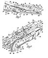
- a seat slide structure designated generally 10 includes an upper track member 12 and a lower track member 14.
- the upper track member 12 includes a base wall 16, a pair of side walls 18 and a pair of terminal flanges 20 which are arcuate.
- the lower track member 14 likewise includes a base wall 22, a pair of side walls 24 and a pair of terminal flanges 26 which are arcuate, with base wall 22 and side walls 24 being located in spaced opposed relationship to respective base wall 16 and side walls 18 of the upper track member 12 and terminal flanges 26 being located in spaced opposed relationship to the terminal flanges 20.
- the upper track member 12 is supported on the lower track member 14 for relative horizontal movement by a pair of bearing assemblies such as those disclosed in US Patent No.4,511,187 or in our copending application No.86300891.8 filed filed 10 February 1986.
- the lower track member 14 is supported on the vehicle, not shown, in a suitable manner, such as by front and rear brackets 28 schematically indicated in Figure 1.
- the upper track member 12 supports a vehicle seat which includes a seat cushion, not shown, and a seat back 30 which is pivoted at 32 to a bracket 34 fixed to the base wall 16 of upper track member 12 for movement between an upright position, as shown; and a forwardly tilted position, not shown, counterclockwise of its position shown.
- a lever 36 is fixed to the seat back 30 for movement therewith for a purpose to be described.
- the upper track member 12 is held in any one of a plurality of horizontally adjusted positions relative to the lower track member 14 by a latch arrangement such as that disclosed in our copending application No.86300892.6 filed 10 par' 1986.
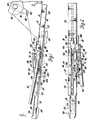
- this latch arrangement includes a latch member 38 having a U-shaped body portion 4) having a slot 42 therein, Figure 3.
- the slot 42 revives the rearward edge portion of a generally rectagular opening 44 in the base wall 16 of the uppe: track member 12 to pivotally and slidably mount the latch member 38 on the upper track member 2 for movement between a latched position as shown in Figures 1, 2 and 4 and an unlatched position as shown in Figure 3, slightly clockwise of its latched position.
- the latch member 38 includes a latch portion 46 which extends inwardly of the rectangular opening 44 and forwardly of the upper track member 12 and terminates in a pair of latch arms or lugs 48 and 50 which are oppositely extending.
- the lug 48 moves vertically within an opening 52 in the base wall 16 of the upper track member 12 and the lug 50 is receivable in any one of a plurality of openings 54 in the base wall 22 of the lower track member 14 to latch the upper track member to the lower track member in a horizontally adjusted position.
- the latch member 38 further includes an arm 56 which extends laterally and outwardly of the upper track member 12 and terminates in an operating arm or portion 58 which receives the rear flattened end 60 of a manual operator 62.
- the manual operator 62 is shown as a tubular member but could be shaped otherwise if desired.
- the latch member 38 is biased to its latched position by first resilient means in the form of a spring 64 which is longitudinally and laterally bowed or arcuate hairpin type, Figures 1 and 2, which encircles the lug 48 and seats on the latch portion 46 adjacent this lug.
- the free ends 66 of the spring 64 extend upwardly through an opening 68 in the base wall 16 of upper track member 12.
- a bracket 70 is fixed to the base wall 16 of upper track member 12.
- the bracket 70 includes a lateral flange 72 which depends therefrom along one side wall 18 of the upper track member 12 and terminates in a lateral tab 74 for a purpose to be described.
- An integral slotted flange 76 extends upwardly from the bracket 70.
- a reinforcement rib 78 is provided between the integral slotted flange 76 and the bracket 70.
- a blocking member 80 of plastic material and of sector shape is pivoted at 82 to the lateral flange 72 of the bracket 70.
- a coil torsion spring 84 provides second resilient means and has one end secured within a slot 86 of the pivot 82 and the other end anchored to the blocking member 80 to bias the blocking member counterclockwise to its unblocking position as shown in Figures 1 and 4.
- the blocking member 80 is located in this position, by engagement with the lateral tab 74 of the bracket 70.
- the output force of the coil torsion spring 84 is much less than that of the spring 64 for a purpose to be described.
- Coupling means in the form of a cable 88 having a sheath 89 has its rearward end anchored at 90 to the lever arm 36.
- the forward end of the sheath 89 of the cable 88 is peripherally slotted and received within the slot 92 of lateral flange 76 to anchor the sheath to the bracket 70.
- the cable extends through a groove 94 in the periphery of the blocking member 80.
- the forward end of the cable 88 has a pin 96 secured thereto which is received within a slot 98 of the blocking member 80 to anchor the cable 88 between the seat back 30 and the blocking member 80.
- the seat back 30 When it is desired to move the seat to the easy entry forwardly displaced position, the seat back 30 is tilted forwardly or rotated counterclockwise about the pivot 32 as viewed in Figure 1. This moves the cable 88 rearwardly and rotates the blocking member 80 clockwise about its pivot 82 from its unblocking position shown in Figures 1 and 4 to its blocking position shown in Figure 3. As the blocking member 80 is rotated to the blocking position, an integral tab or lug 100 of the blocking member rotates the manual operator 62 from its Figure 4 position to its Figure 3 position wherein the manual operator seats on wall 102 of the lug 100 and concurrently moves the latch member 38 to its unlatched position. The seat can then be displaced forwardly to the easy entry position.
- the lug 50 Upon rearward movement of the seat from the easy entry position, the lug 50 will engage operable means in the form of a dimple or abutment 104, Figure 3, which is located in the base wall 22 of the lower track member 14 approximately at the midpoint in the range of adjustment of upper track member 12 relative to lower track member 14.
- the latch member 38 When the lug 50 engages the abutment 104, the latch member 38 is rotated slightly clockwise to a more unlatched position so that the manual operator 62 is lifted off the wall 102 of lug 100.
- Coil torsion spring 84 thereupon rotates the blocking member 80 counterclockwise to its unblocked position.
- this invention provides an improved easy entry seat adjuster in that it permits continued easy entry movement of a seat should the tilted seat back be returned to an upright position.
Landscapes
- Engineering & Computer Science (AREA)
- Aviation & Aerospace Engineering (AREA)
- Transportation (AREA)
- Mechanical Engineering (AREA)
- Seats For Vehicles (AREA)
Applications Claiming Priority (2)
| Application Number | Priority Date | Filing Date | Title |
|---|---|---|---|
| US06/715,912 US4569557A (en) | 1985-03-25 | 1985-03-25 | Easy entry seat adjuster |
| US715912 | 1985-03-25 |
Publications (1)
| Publication Number | Publication Date |
|---|---|
| EP0196773A2 true EP0196773A2 (de) | 1986-10-08 |
Family
ID=24875980
Family Applications (1)
| Application Number | Title | Priority Date | Filing Date |
|---|---|---|---|
| EP86301358A Withdrawn EP0196773A2 (de) | 1985-03-25 | 1986-02-26 | Vorrichtung zum Einstellen eines Sitzes zum Erleichtern des Zugangs |
Country Status (4)
| Country | Link |
|---|---|
| US (1) | US4569557A (de) |
| EP (1) | EP0196773A2 (de) |
| JP (1) | JPS61229624A (de) |
| CA (1) | CA1254825A (de) |
Cited By (2)
| Publication number | Priority date | Publication date | Assignee | Title |
|---|---|---|---|---|
| EP0286693A1 (de) * | 1987-03-19 | 1988-10-19 | C. Rob. Hammerstein GmbH | Kraftfahrzeugsitz, der durch Kippen seiner Rückenlehne längsverschiebbar ist |
| EP0723889A1 (de) * | 1995-01-30 | 1996-07-31 | Bertrand Faure Equipements S.A. | Fahrzeugsitzgleitschiene |
Families Citing this family (13)
| Publication number | Priority date | Publication date | Assignee | Title |
|---|---|---|---|---|
| CA1246430A (en) * | 1985-06-18 | 1988-12-13 | Dukecal J. Harding | Seat assembly |
| US4671571A (en) * | 1986-06-16 | 1987-06-09 | General Motors Corporation | Easy entry seat adjuster slide |
| US5352019A (en) * | 1993-06-18 | 1994-10-04 | Firma C. Rob. Hammerstein Gmbh | Motor vehicle seat movable in the longitudinal direction in the tipped state |
| FR2710011B1 (fr) * | 1993-09-16 | 1995-12-08 | Cesa | Glissière à condamnation, notamment pour sièges de véhicules automobiles. |
| US5957535A (en) * | 1996-03-29 | 1999-09-28 | Dura Automotive Systems, Inc. | Seat track assembly with vertical dislocation resistance bracket |
| US5785387A (en) * | 1996-09-23 | 1998-07-28 | Excel Industries, Inc. | Vehicle seat assembly with position-fixing means |
| US5893545A (en) * | 1997-10-23 | 1999-04-13 | Excel Industries, Inc. | Seat track assembly with enhanced vertical dislocation resistance |
| CA2255432C (en) * | 1997-12-12 | 2008-03-04 | Magna Interior Systems Inc. | Bench seat having track assembly with bi-directional release |
| DE102005026861B4 (de) * | 2004-12-23 | 2019-02-28 | Adient Luxembourg Holding S.À R.L. | Vorverlagerbarer Fahrzeugsitz mit einem Untergestell und zwei Schienenpaaren |
| US20080252126A1 (en) * | 2007-04-10 | 2008-10-16 | Lear Corporation | Power actuated easy entry seat |
| US9776532B2 (en) | 2013-09-20 | 2017-10-03 | Lear Corporation | Easy entry seat track adjuster |
| US9340125B2 (en) | 2013-09-20 | 2016-05-17 | Lear Corporation | Easy entry adjustable end stop |
| US10214119B2 (en) | 2013-09-20 | 2019-02-26 | Lear Corporation | Track adjuster |
Family Cites Families (5)
| Publication number | Priority date | Publication date | Assignee | Title |
|---|---|---|---|---|
| JPS5031522A (de) * | 1973-07-23 | 1975-03-28 | ||
| JPS5047319A (de) * | 1973-08-31 | 1975-04-26 | ||
| JPS52105428A (en) * | 1976-02-27 | 1977-09-03 | Nissan Motor Co Ltd | Memory including seat for walk-in rail |
| FR2378649A1 (fr) * | 1977-01-26 | 1978-08-25 | Toyo Kogyo Co | Mecanisme de liberation de verrouillage pour siege avant de vehicule |
| US4440442A (en) * | 1982-02-11 | 1984-04-03 | General Motors Corporation | Seat position control mechanism |
-
1985
- 1985-03-25 US US06/715,912 patent/US4569557A/en not_active Expired - Lifetime
- 1985-11-19 CA CA000495620A patent/CA1254825A/en not_active Expired
-
1986
- 1986-02-26 EP EP86301358A patent/EP0196773A2/de not_active Withdrawn
- 1986-03-25 JP JP61065001A patent/JPS61229624A/ja active Pending
Cited By (4)
| Publication number | Priority date | Publication date | Assignee | Title |
|---|---|---|---|---|
| EP0286693A1 (de) * | 1987-03-19 | 1988-10-19 | C. Rob. Hammerstein GmbH | Kraftfahrzeugsitz, der durch Kippen seiner Rückenlehne längsverschiebbar ist |
| EP0723889A1 (de) * | 1995-01-30 | 1996-07-31 | Bertrand Faure Equipements S.A. | Fahrzeugsitzgleitschiene |
| FR2729898A1 (fr) * | 1995-01-30 | 1996-08-02 | Faure Bertrand Equipements Sa | Perfectionnements aux glissieres pour sieges de vehicules et aux sieges equipes de telles glissieres |
| US5688026A (en) * | 1995-01-30 | 1997-11-18 | Bertrand Faure Equipements Sa | Slides for vehicle seats, and to seats fitted with such slides |
Also Published As
| Publication number | Publication date |
|---|---|
| US4569557A (en) | 1986-02-11 |
| CA1254825A (en) | 1989-05-30 |
| JPS61229624A (ja) | 1986-10-13 |
Similar Documents
| Publication | Publication Date | Title |
|---|---|---|
| EP0196773A2 (de) | Vorrichtung zum Einstellen eines Sitzes zum Erleichtern des Zugangs | |
| EP0201163A2 (de) | Vorrichtung zum Einstellen eines Sitzes zum Erleichtern des Zugangs | |
| US6616233B1 (en) | Slide rail for vehicle seat and seat comprising such a slide rail | |
| US5707092A (en) | Self-aligning loop striker | |
| JP4038246B2 (ja) | フルリターンまでシートバックロックアウトを有するイージーエントリーシート | |
| US4159147A (en) | Latch releasing mechanism for use in a front seat of a vehicle | |
| US4440442A (en) | Seat position control mechanism | |
| US7533934B2 (en) | Vehicle seat | |
| EP0411850A2 (de) | Fahrzeugsitzverstellvorrichtung | |
| US4015877A (en) | Vehicle seat assemblies | |
| US3973288A (en) | Seat recliner | |
| US5855413A (en) | Slideway for a vehicle seat, and a seat including such a slideway | |
| US4880264A (en) | Latch device for inclinable back rest cushion mounted in seatback | |
| US4057306A (en) | Gang luck assembly for cabinet drawers | |
| JPH0212772B2 (de) | ||
| JP2003527990A (ja) | 乗込みの容易なシート軌道組立体 | |
| US6102478A (en) | Vehicle seat slide mechanism | |
| US4438895A (en) | Vertical seat adjuster for vehicle seats | |
| US6830295B2 (en) | Fixing device for fixing a seat to a vehicle floor, and a seat equipped with such a fixing device | |
| US4422690A (en) | Seat position control mechanism | |
| EP0094141A2 (de) | Verstellbare Befestigungsvorrichtung für einen Fahrzeugsitz | |
| EP0194754A2 (de) | Sitzgleitkonstruktion und Feststellkonstruktion dafür | |
| EP0195508A2 (de) | Sitzschienenaufbau und Verriegelungsaufbau dafür | |
| US5358303A (en) | Roof panel for a motor vehicle | |
| JP3546471B2 (ja) | シートバックのロック装置 |
Legal Events
| Date | Code | Title | Description |
|---|---|---|---|
| PUAI | Public reference made under article 153(3) epc to a published international application that has entered the european phase |
Free format text: ORIGINAL CODE: 0009012 |
|
| 17P | Request for examination filed |
Effective date: 19860306 |
|
| AK | Designated contracting states |
Kind code of ref document: A2 Designated state(s): DE GB |
|
| STAA | Information on the status of an ep patent application or granted ep patent |
Free format text: STATUS: THE APPLICATION HAS BEEN WITHDRAWN |
|
| 18W | Application withdrawn |
Withdrawal date: 19871110 |
|
| RIN1 | Information on inventor provided before grant (corrected) |
Inventor name: GOFORTH, WILLIAM RAY |