EP0196690B1 - Energieaufschlag und Rückgewinnung - Google Patents
Energieaufschlag und Rückgewinnung Download PDFInfo
- Publication number
- EP0196690B1 EP0196690B1 EP86200305A EP86200305A EP0196690B1 EP 0196690 B1 EP0196690 B1 EP 0196690B1 EP 86200305 A EP86200305 A EP 86200305A EP 86200305 A EP86200305 A EP 86200305A EP 0196690 B1 EP0196690 B1 EP 0196690B1
- Authority
- EP
- European Patent Office
- Prior art keywords
- storage space
- liquid
- gas
- pump
- storage
- Prior art date
- Legal status (The legal status is an assumption and is not a legal conclusion. Google has not performed a legal analysis and makes no representation as to the accuracy of the status listed.)
- Expired
Links
- 239000007788 liquid Substances 0.000 claims abstract description 53
- 238000005086 pumping Methods 0.000 claims abstract description 6
- 239000007789 gas Substances 0.000 claims description 46
- IJGRMHOSHXDMSA-UHFFFAOYSA-N Atomic nitrogen Chemical compound N#N IJGRMHOSHXDMSA-UHFFFAOYSA-N 0.000 claims description 6
- VNWKTOKETHGBQD-UHFFFAOYSA-N methane Chemical compound C VNWKTOKETHGBQD-UHFFFAOYSA-N 0.000 claims description 6
- 238000011084 recovery Methods 0.000 claims description 6
- 238000000034 method Methods 0.000 claims description 5
- CURLTUGMZLYLDI-UHFFFAOYSA-N Carbon dioxide Chemical compound O=C=O CURLTUGMZLYLDI-UHFFFAOYSA-N 0.000 claims description 4
- XLYOFNOQVPJJNP-UHFFFAOYSA-N water Substances O XLYOFNOQVPJJNP-UHFFFAOYSA-N 0.000 claims description 4
- 229910052757 nitrogen Inorganic materials 0.000 claims description 3
- 239000012267 brine Substances 0.000 claims description 2
- 229910002092 carbon dioxide Inorganic materials 0.000 claims description 2
- 239000001569 carbon dioxide Substances 0.000 claims description 2
- 238000004891 communication Methods 0.000 claims description 2
- 239000003915 liquefied petroleum gas Substances 0.000 claims description 2
- HPALAKNZSZLMCH-UHFFFAOYSA-M sodium;chloride;hydrate Chemical compound O.[Na+].[Cl-] HPALAKNZSZLMCH-UHFFFAOYSA-M 0.000 claims description 2
- 238000006073 displacement reaction Methods 0.000 claims 1
- 239000003921 oil Substances 0.000 claims 1
- 235000002639 sodium chloride Nutrition 0.000 description 5
- 239000011435 rock Substances 0.000 description 3
- 150000003839 salts Chemical class 0.000 description 3
- FAPWRFPIFSIZLT-UHFFFAOYSA-M Sodium chloride Chemical group [Na+].[Cl-] FAPWRFPIFSIZLT-UHFFFAOYSA-M 0.000 description 2
- 230000015572 biosynthetic process Effects 0.000 description 2
- 230000006835 compression Effects 0.000 description 2
- 238000007906 compression Methods 0.000 description 2
- 239000012530 fluid Substances 0.000 description 2
- 239000011780 sodium chloride Substances 0.000 description 2
- 230000001133 acceleration Effects 0.000 description 1
- 238000004146 energy storage Methods 0.000 description 1
- 230000002349 favourable effect Effects 0.000 description 1
- 230000005484 gravity Effects 0.000 description 1
- 238000009434 installation Methods 0.000 description 1
- 239000003345 natural gas Substances 0.000 description 1
Images

Classifications
-
- E—FIXED CONSTRUCTIONS
- E21—EARTH OR ROCK DRILLING; MINING
- E21B—EARTH OR ROCK DRILLING; OBTAINING OIL, GAS, WATER, SOLUBLE OR MELTABLE MATERIALS OR A SLURRY OF MINERALS FROM WELLS
- E21B41/00—Equipment or details not covered by groups E21B15/00 - E21B40/00
- E21B41/005—Waste disposal systems
- E21B41/0057—Disposal of a fluid by injection into a subterranean formation
- E21B41/0064—Carbon dioxide sequestration
-
- F—MECHANICAL ENGINEERING; LIGHTING; HEATING; WEAPONS; BLASTING
- F03—MACHINES OR ENGINES FOR LIQUIDS; WIND, SPRING, OR WEIGHT MOTORS; PRODUCING MECHANICAL POWER OR A REACTIVE PROPULSIVE THRUST, NOT OTHERWISE PROVIDED FOR
- F03B—MACHINES OR ENGINES FOR LIQUIDS
- F03B13/00—Adaptations of machines or engines for special use; Combinations of machines or engines with driving or driven apparatus; Power stations or aggregates
- F03B13/06—Stations or aggregates of water-storage type, e.g. comprising a turbine and a pump
-
- F—MECHANICAL ENGINEERING; LIGHTING; HEATING; WEAPONS; BLASTING
- F03—MACHINES OR ENGINES FOR LIQUIDS; WIND, SPRING, OR WEIGHT MOTORS; PRODUCING MECHANICAL POWER OR A REACTIVE PROPULSIVE THRUST, NOT OTHERWISE PROVIDED FOR
- F03B—MACHINES OR ENGINES FOR LIQUIDS
- F03B17/00—Other machines or engines
- F03B17/02—Other machines or engines using hydrostatic thrust
-
- Y—GENERAL TAGGING OF NEW TECHNOLOGICAL DEVELOPMENTS; GENERAL TAGGING OF CROSS-SECTIONAL TECHNOLOGIES SPANNING OVER SEVERAL SECTIONS OF THE IPC; TECHNICAL SUBJECTS COVERED BY FORMER USPC CROSS-REFERENCE ART COLLECTIONS [XRACs] AND DIGESTS
- Y02—TECHNOLOGIES OR APPLICATIONS FOR MITIGATION OR ADAPTATION AGAINST CLIMATE CHANGE
- Y02C—CAPTURE, STORAGE, SEQUESTRATION OR DISPOSAL OF GREENHOUSE GASES [GHG]
- Y02C20/00—Capture or disposal of greenhouse gases
- Y02C20/40—Capture or disposal of greenhouse gases of CO2
-
- Y—GENERAL TAGGING OF NEW TECHNOLOGICAL DEVELOPMENTS; GENERAL TAGGING OF CROSS-SECTIONAL TECHNOLOGIES SPANNING OVER SEVERAL SECTIONS OF THE IPC; TECHNICAL SUBJECTS COVERED BY FORMER USPC CROSS-REFERENCE ART COLLECTIONS [XRACs] AND DIGESTS
- Y02—TECHNOLOGIES OR APPLICATIONS FOR MITIGATION OR ADAPTATION AGAINST CLIMATE CHANGE
- Y02E—REDUCTION OF GREENHOUSE GAS [GHG] EMISSIONS, RELATED TO ENERGY GENERATION, TRANSMISSION OR DISTRIBUTION
- Y02E10/00—Energy generation through renewable energy sources
- Y02E10/20—Hydro energy
-
- Y—GENERAL TAGGING OF NEW TECHNOLOGICAL DEVELOPMENTS; GENERAL TAGGING OF CROSS-SECTIONAL TECHNOLOGIES SPANNING OVER SEVERAL SECTIONS OF THE IPC; TECHNICAL SUBJECTS COVERED BY FORMER USPC CROSS-REFERENCE ART COLLECTIONS [XRACs] AND DIGESTS
- Y02—TECHNOLOGIES OR APPLICATIONS FOR MITIGATION OR ADAPTATION AGAINST CLIMATE CHANGE
- Y02E—REDUCTION OF GREENHOUSE GAS [GHG] EMISSIONS, RELATED TO ENERGY GENERATION, TRANSMISSION OR DISTRIBUTION
- Y02E60/00—Enabling technologies; Technologies with a potential or indirect contribution to GHG emissions mitigation
- Y02E60/16—Mechanical energy storage, e.g. flywheels or pressurised fluids
Definitions
- the invention relates to a system for the storage and recovery of energy comprising a first storage space partly filled with liquid, a second storage space which is partly filled with gas, the lower part of the first storage space being liquid-connected to the lower part of the second storage space and wherein a pump is situated at approximately the same height as, or above, the first storage space, and is provided with means for interrupting the flow of liquid, in order, during normal operation, to be able to pump liquid from the first storage space to the second storage space resulting in the gas being compressed, or to be driven by liquid displaced from the second storage space by the expanding gas to flow back to the first storage space.
- FR-A-1,006,464 only relates to an overground installation for producing electric energy by means of wind or the pressure of flowing water and cannot be used for underground energy storage by means of compression and expansion of a gas cushion or gas spring in an underground space or cavern.
- the system of the invention therefore is characterized in that the said system comprises a pump/turbine unit which is in liquid connection in the line between the first storage space and the second storage space, and wherein the second storage space is an underground space or cavern.
- the first storage space can also contain gas that forms a gas cushion above the liquid.
- the second storage space is situated below the first storage space.
- the second storage space can be an underground space, which can be formed in any hard rock.
- a particularly suitable rock is rock salt. This has the advantage that the underground space can be formed by dissolving the salt.
- the first storage space is also an underground space. In that case, it is favourable to form both underground storage spaces in rock salt.
- the first storage space consists of a lake at a high location and the second storage space consists of a second lake at a lower location or of an underground cavern, and there is a connecting line between the lower part of the first storage space and the lower part of the second storage space.
- the pump/turbine unit is installed in the connecting line and located at the same height as the lower, second space in order, during normal operation, to be able to pump a liquid from the second storage space to the higher, first storage space, or to be driven by the liquid flowing back from the higher, first storage space to the lower, second storage space.
- the pump of such a system is usually driven by an electric motor connected by an electric line to an electric network, and the turbine then drives an electric generator which is also connected to an electric line to an electric network.
- Such a system enables an excess of electrical energy to be used to pump the liquid to the higher, first storage space, while a shortage of electrical energy can be supplemented by electrical energy generated by the electric generator driven by the turbine, which is itself driven by liquid flowing back to the lower, second storage space.
- the pump/turbine unit Since the pump/turbine unit is installed near the lower, second storage space, it is necessary in the case of the second storage space being an underground cavern, in addition to this storage space to make a separate space for the pump/turbine unit and to make a separate shaft through which to run an electric line os sufficient size to carry the electrical energy to the electric motor and from the electric generator. This makes such a system extremely costly.
- the invention also relates to a process for the storage and recovery of energy with the aid of the system according to the invention, characterized by the steps of:
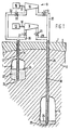
- the system for storing and recovering energy comprises a first underground storage space 1 formed in a salt dome 2 situated beneath an earth layer 3, and a second underground storage space 5 situated on the salt dome 2 below the first storage space 1.
- the system further comprises a pump/turbine unit 8 located at ground level 7 shows the first storage space 1, the pump/turbine unit consisting of a pump 9 connected by a shaft 10 to an electric motor 13, and a turbine 14 connected by a shaft 15 to an electric generator 16.
- the pump/turbine unit 8 is connected to the lower part of the first storage space 1 by a first line 17, and to the lower part of the second storage space 5 by a second line 18.
- the first line 17 comprises a bore-hole provided with a tube 19
- the second line 18 comprises a bore-hole provided with a tube 20.
- the electric motor 13 is connected by an electric line (not shown) to en electric network (not shown) in order to draw electrical energy from it, and the electric generator 16 is connected by an electric line (not shown) to the electric network in order to supply electrical energy to it.
- the first storage space 1 is partly filled with a liquid, viz. brine 22 having a density of 1200 kg/ m 3
- the second storage space 5 is partly filled with a gas, viz. nitrogen, that serves as a gas cushion.
- the liquid is also to be found in the first line 17, the pump/turbine unit 8, the second line 18 and the lower part of the second storage space 5; and the gas is also to be found in the upper part of the first storage space 1 as a gas cushion above the liquid 22.
- the numeral 24 refers to the interface between the two fluids in the first storage space 1 and the numeral 25 to the interface between the two fluids in the second storage space 5.
- the inlet of the pump 9 is connected to the first line 17 by means of a supply pipe 26 provided with a shut-off valve 27, and the outlet of the pump 9 is connected to the second line 18 by a discharge pipe 28 provided with a shut-off valve 29.
- the inlet of the turbine 14 is connected to the second line 18 by means of a supply pipe 30 provided with a shut-off valve 31, and the outlet of the turbine 14 is connected to the first line 17 by a discharge pipe 32 provided with a shut-off valve 33.
- shut-off valves 31 and 33 When it is necessary to recover the stored energy, for example in the case of a large demand for electrical energy, just the shut-off valves 31 and 33 will be opened. Liquid, driven by the expanding gas, will then flow back from the second storage space 5 to the first storage space 1 via the second line 18, the turbine 14 and the first line 17. The returning liquid causes the turbine 14 to move, which drives the electric generator 16, and this in turn generates electrical energy which can be fed into the electric network.
- the gas in the second storage space 5 When the gas in the second storage space 5 has expanded sufficiently, the return flow of the liquid is interrupted by closing the shut-off valves 31 and 33. The system will then again be in its stationary situation.
- the gas pressure in the first storage space 1 and the height of the liquid column in the first line 17 must be chosen such that the liquid pressure in the supply line 26 near the shut-off valve 27 remains slightly above atmospheric pressure, so that when liquid is pumped out of the first storage space 1, the supply of liquid to the pump remains assured. Precautions must also be taken to ensure that the interface 25 in the second storage space 5 cannot fall to below the level of the opening 35 of the second line 18, so that no gas can flow into the second line 18.
- the pump and turbine are separate, but the pump/turbine unit can also consist of a hydraulic machine which can function both as pump (or compressor) and as turbine, which hydraulic machine is connected to an electric machine which can function both as motor and generator.
- this can be provided with a heat exchanger (not shown) to cool the liquid.
- the first storage space can also be situated at ground level, for example in the form of an above-ground storage tank or a lake.
- the above-ground pump/turbine unit will be at about the same height as the first storage space. It will then not be necessary to have a gas cushion above the liquid in the first storage space.
- the gas may consist of carbon dioxide, nitrogen or methane.
- the liquid may also be oil or liquefied petroleum gas.
- Water can also be used, in particular if the underground part of the system is formed in a rock which is not affected by water.
- a suitable system for storing and recovering 100 MW of electrical power has underground storage spaces able to contain about 5x 10 5 m 3 to 6x10 5 m 3 of liquid and in which the second storage space can contain about 2x10 6 m 3 of gas und is situated at a depth of about 1500 m.
- the areas of the passages of the first and second lines should be as large as possible, at least 1.8 m 2 .
- the highest gas pressure in the storage space will be chosen between about 1.3 times the formation pressure at the storage space (being the sum over all earth layers above the storage space of the product of the thickness and the specific mass of each of the earth layers multiplied by the acceleration of gravity) and a pressure equal to about half of the formation pressure.
- the highest gas pressure can be chosen between 40 MPa and 15 MPa, and for an upper storage space, situated at a dpeth of 500 m, between 12 MPa and 6 MPa.
- the gas pressure will vary between this highest gas pressure and a pressure which is 10-20% lower. This pressure difference is chosen such that only a small amount of heat is released by the compression of the gas.
- an additional gas storage space 36 (see Figure 2) is provided near the second storage space 5.
- the top of the additional gas storage space 36 is in open communication with the top of the second storage space 5.
- the system can also comprise a turbine (not shown) to drive the pump 9.
- the turbine is itself driven be a compressed gas, for example natural gas.
Landscapes
- Engineering & Computer Science (AREA)
- Chemical & Material Sciences (AREA)
- Geology (AREA)
- Combustion & Propulsion (AREA)
- Mechanical Engineering (AREA)
- General Engineering & Computer Science (AREA)
- Environmental & Geological Engineering (AREA)
- Mining & Mineral Resources (AREA)
- Life Sciences & Earth Sciences (AREA)
- Chemical Kinetics & Catalysis (AREA)
- Fluid Mechanics (AREA)
- Physics & Mathematics (AREA)
- General Life Sciences & Earth Sciences (AREA)
- Geochemistry & Mineralogy (AREA)
- Filling Or Discharging Of Gas Storage Vessels (AREA)
- Engine Equipment That Uses Special Cycles (AREA)
- Memory System Of A Hierarchy Structure (AREA)
- Supply And Distribution Of Alternating Current (AREA)
- Electrical Discharge Machining, Electrochemical Machining, And Combined Machining (AREA)
- Physical Or Chemical Processes And Apparatus (AREA)
- Other Liquid Machine Or Engine Such As Wave Power Use (AREA)
Claims (9)
Priority Applications (1)
| Application Number | Priority Date | Filing Date | Title |
|---|---|---|---|
| AT86200305T ATE47467T1 (de) | 1985-03-28 | 1986-02-27 | Energieaufschlag und rueckgewinnung. |
Applications Claiming Priority (2)
| Application Number | Priority Date | Filing Date | Title |
|---|---|---|---|
| NL8500911 | 1985-03-28 | ||
| NL8500911 | 1985-03-28 |
Publications (2)
| Publication Number | Publication Date |
|---|---|
| EP0196690A1 EP0196690A1 (de) | 1986-10-08 |
| EP0196690B1 true EP0196690B1 (de) | 1989-10-18 |
Family
ID=19845752
Family Applications (1)
| Application Number | Title | Priority Date | Filing Date |
|---|---|---|---|
| EP86200305A Expired EP0196690B1 (de) | 1985-03-28 | 1986-02-27 | Energieaufschlag und Rückgewinnung |
Country Status (6)
| Country | Link |
|---|---|
| EP (1) | EP0196690B1 (de) |
| JP (1) | JPS61226571A (de) |
| AT (1) | ATE47467T1 (de) |
| CA (1) | CA1260802A (de) |
| DE (1) | DE3666489D1 (de) |
| DK (1) | DK140386A (de) |
Cited By (28)
| Publication number | Priority date | Publication date | Assignee | Title |
|---|---|---|---|---|
| US7900444B1 (en) | 2008-04-09 | 2011-03-08 | Sustainx, Inc. | Systems and methods for energy storage and recovery using compressed gas |
| US7958731B2 (en) | 2009-01-20 | 2011-06-14 | Sustainx, Inc. | Systems and methods for combined thermal and compressed gas energy conversion systems |
| US7963110B2 (en) | 2009-03-12 | 2011-06-21 | Sustainx, Inc. | Systems and methods for improving drivetrain efficiency for compressed gas energy storage |
| US8037677B2 (en) | 2009-06-29 | 2011-10-18 | Lightsail Energy, Inc. | Compressed air energy storage system utilizing two-phase flow to facilitate heat exchange |
| US8037678B2 (en) | 2009-09-11 | 2011-10-18 | Sustainx, Inc. | Energy storage and generation systems and methods using coupled cylinder assemblies |
| US8046990B2 (en) | 2009-06-04 | 2011-11-01 | Sustainx, Inc. | Systems and methods for improving drivetrain efficiency for compressed gas energy storage and recovery systems |
| US8061132B2 (en) | 2009-06-29 | 2011-11-22 | Lightsail Energy, Inc. | Compressed air energy storage system utilizing two-phase flow to facilitate heat exchange |
| US8104274B2 (en) | 2009-06-04 | 2012-01-31 | Sustainx, Inc. | Increased power in compressed-gas energy storage and recovery |
| US8117842B2 (en) | 2009-11-03 | 2012-02-21 | Sustainx, Inc. | Systems and methods for compressed-gas energy storage using coupled cylinder assemblies |
| US8171728B2 (en) | 2010-04-08 | 2012-05-08 | Sustainx, Inc. | High-efficiency liquid heat exchange in compressed-gas energy storage systems |
| US8191362B2 (en) | 2010-04-08 | 2012-06-05 | Sustainx, Inc. | Systems and methods for reducing dead volume in compressed-gas energy storage systems |
| US8225606B2 (en) | 2008-04-09 | 2012-07-24 | Sustainx, Inc. | Systems and methods for energy storage and recovery using rapid isothermal gas expansion and compression |
| US8234863B2 (en) | 2010-05-14 | 2012-08-07 | Sustainx, Inc. | Forming liquid sprays in compressed-gas energy storage systems for effective heat exchange |
| WO2012103591A1 (en) * | 2011-02-04 | 2012-08-09 | Weswood Pty Ltd | Differential pressure energy generation |
| US8240146B1 (en) | 2008-06-09 | 2012-08-14 | Sustainx, Inc. | System and method for rapid isothermal gas expansion and compression for energy storage |
| US8240140B2 (en) | 2008-04-09 | 2012-08-14 | Sustainx, Inc. | High-efficiency energy-conversion based on fluid expansion and compression |
| US8247915B2 (en) | 2010-03-24 | 2012-08-21 | Lightsail Energy, Inc. | Energy storage system utilizing compressed gas |
| US8250863B2 (en) | 2008-04-09 | 2012-08-28 | Sustainx, Inc. | Heat exchange with compressed gas in energy-storage systems |
| US8436489B2 (en) | 2009-06-29 | 2013-05-07 | Lightsail Energy, Inc. | Compressed air energy storage system utilizing two-phase flow to facilitate heat exchange |
| US8448433B2 (en) | 2008-04-09 | 2013-05-28 | Sustainx, Inc. | Systems and methods for energy storage and recovery using gas expansion and compression |
| US8474255B2 (en) | 2008-04-09 | 2013-07-02 | Sustainx, Inc. | Forming liquid sprays in compressed-gas energy storage systems for effective heat exchange |
| US8479505B2 (en) | 2008-04-09 | 2013-07-09 | Sustainx, Inc. | Systems and methods for reducing dead volume in compressed-gas energy storage systems |
| US8495872B2 (en) | 2010-08-20 | 2013-07-30 | Sustainx, Inc. | Energy storage and recovery utilizing low-pressure thermal conditioning for heat exchange with high-pressure gas |
| US8539763B2 (en) | 2011-05-17 | 2013-09-24 | Sustainx, Inc. | Systems and methods for efficient two-phase heat transfer in compressed-air energy storage systems |
| US8578708B2 (en) | 2010-11-30 | 2013-11-12 | Sustainx, Inc. | Fluid-flow control in energy storage and recovery systems |
| US8667792B2 (en) | 2011-10-14 | 2014-03-11 | Sustainx, Inc. | Dead-volume management in compressed-gas energy storage and recovery systems |
| US8677744B2 (en) | 2008-04-09 | 2014-03-25 | SustaioX, Inc. | Fluid circulation in energy storage and recovery systems |
| US8733095B2 (en) | 2008-04-09 | 2014-05-27 | Sustainx, Inc. | Systems and methods for efficient pumping of high-pressure fluids for energy |
Families Citing this family (18)
| Publication number | Priority date | Publication date | Assignee | Title |
|---|---|---|---|---|
| DE3667705D1 (de) * | 1985-08-06 | 1990-01-25 | Shell Int Research | Speicherung und rueckgewinnung von energie. |
| NL8601342A (nl) * | 1986-05-26 | 1987-12-16 | Ir Arnold Willem Josephus Grup | Stelsel voor ondergrondse energie-opslag. |
| JPH0612109B2 (ja) * | 1990-06-11 | 1994-02-16 | 財団法人電力中央研究所 | 自然エネルギーの貯蔵方法及び貯蔵システム |
| SK279395B6 (sk) * | 1995-06-23 | 1998-11-04 | Fridrich Zeman | Jednotný energetický blok |
| CN1086776C (zh) * | 2000-04-17 | 2002-06-26 | 郭元生 | 多水源水力发电的设备和方法 |
| US6718761B2 (en) * | 2001-04-10 | 2004-04-13 | New World Generation Inc. | Wind powered hydroelectric power plant and method of operation thereof |
| ES2246621B1 (es) * | 2003-01-23 | 2007-06-01 | Severino Suarez Fernandez | Sistema de explotacion hidroelectrica de un pozo minero. |
| CN100366895C (zh) * | 2003-06-21 | 2008-02-06 | 陆健 | 一种利用水位落差提水或提供动力的系统 |
| EP2158389A4 (de) | 2007-05-09 | 2016-03-23 | Ecole Polytechnique Fédérale De Lausanne Epfl | Energiespeichersysteme |
| CN104895745A (zh) * | 2009-05-22 | 2015-09-09 | 通用压缩股份有限公司 | 压缩机和/或膨胀机装置 |
| GB201002937D0 (en) * | 2010-02-22 | 2010-04-07 | Champion Hilary | Energy storage device |
| EP2486988B1 (de) * | 2011-02-11 | 2013-07-31 | Luxin (Green Planet) AG | Unterirdisches Wassermanagementsystem für Minen und Verfahren zum Betrieb dieses Wassermanagementsystems |
| DE102011106040A1 (de) * | 2011-06-25 | 2012-12-27 | Armin Dadgar | Pumpspeicherkraftwerk |
| ES2688211T3 (es) * | 2015-12-22 | 2018-10-31 | Renestor-M Gmbh | Sistema de almacenamiento y recuperación de energía |
| US10837360B2 (en) | 2018-03-13 | 2020-11-17 | Maxim Raskin | System for energy storage and recovery |
| ES2989873T3 (es) * | 2018-04-16 | 2024-11-28 | Magellan & Barents S L | Sistema y método de almacenamiento de energía hidráulica por bombeo |
| WO2023148553A1 (en) | 2022-02-02 | 2023-08-10 | Rasmussen John Dane | Systems and methods for subterranean energy storage |
| CN115142831B (zh) * | 2022-06-23 | 2024-04-26 | 江苏国能石油天然气有限公司 | 一种利用盐穴储气库卤水余压驱动mvr制盐的方法 |
Family Cites Families (5)
| Publication number | Priority date | Publication date | Assignee | Title |
|---|---|---|---|---|
| DE215657C (de) * | 1900-01-01 | |||
| FR1006464A (fr) * | 1948-01-19 | 1952-04-23 | Installation de force motrice pour la production d'énergie électrique, notamment pour les usages domestiques et les ateliers | |
| US4086765A (en) * | 1977-02-11 | 1978-05-02 | James Gillilan | Power generating system |
| JPS578363A (en) * | 1980-06-19 | 1982-01-16 | Kenji Horii | Energy storage generator using submarine compressed air tank |
| JPS58178878A (ja) * | 1982-04-14 | 1983-10-19 | Mitsui Eng & Shipbuild Co Ltd | 揚水発電装置 |
-
1986
- 1986-02-27 EP EP86200305A patent/EP0196690B1/de not_active Expired
- 1986-02-27 DE DE8686200305T patent/DE3666489D1/de not_active Expired
- 1986-02-27 AT AT86200305T patent/ATE47467T1/de not_active IP Right Cessation
- 1986-03-18 CA CA000504327A patent/CA1260802A/en not_active Expired
- 1986-03-26 DK DK140386A patent/DK140386A/da not_active Application Discontinuation
- 1986-03-26 JP JP61068272A patent/JPS61226571A/ja active Pending
Cited By (53)
| Publication number | Priority date | Publication date | Assignee | Title |
|---|---|---|---|---|
| US8474255B2 (en) | 2008-04-09 | 2013-07-02 | Sustainx, Inc. | Forming liquid sprays in compressed-gas energy storage systems for effective heat exchange |
| US8448433B2 (en) | 2008-04-09 | 2013-05-28 | Sustainx, Inc. | Systems and methods for energy storage and recovery using gas expansion and compression |
| US8225606B2 (en) | 2008-04-09 | 2012-07-24 | Sustainx, Inc. | Systems and methods for energy storage and recovery using rapid isothermal gas expansion and compression |
| US8763390B2 (en) | 2008-04-09 | 2014-07-01 | Sustainx, Inc. | Heat exchange with compressed gas in energy-storage systems |
| US8733094B2 (en) | 2008-04-09 | 2014-05-27 | Sustainx, Inc. | Systems and methods for energy storage and recovery using rapid isothermal gas expansion and compression |
| US8733095B2 (en) | 2008-04-09 | 2014-05-27 | Sustainx, Inc. | Systems and methods for efficient pumping of high-pressure fluids for energy |
| US8240140B2 (en) | 2008-04-09 | 2012-08-14 | Sustainx, Inc. | High-efficiency energy-conversion based on fluid expansion and compression |
| US8713929B2 (en) | 2008-04-09 | 2014-05-06 | Sustainx, Inc. | Systems and methods for energy storage and recovery using compressed gas |
| US8677744B2 (en) | 2008-04-09 | 2014-03-25 | SustaioX, Inc. | Fluid circulation in energy storage and recovery systems |
| US8250863B2 (en) | 2008-04-09 | 2012-08-28 | Sustainx, Inc. | Heat exchange with compressed gas in energy-storage systems |
| US8209974B2 (en) | 2008-04-09 | 2012-07-03 | Sustainx, Inc. | Systems and methods for energy storage and recovery using compressed gas |
| US8479505B2 (en) | 2008-04-09 | 2013-07-09 | Sustainx, Inc. | Systems and methods for reducing dead volume in compressed-gas energy storage systems |
| US8627658B2 (en) | 2008-04-09 | 2014-01-14 | Sustainx, Inc. | Systems and methods for energy storage and recovery using rapid isothermal gas expansion and compression |
| US7900444B1 (en) | 2008-04-09 | 2011-03-08 | Sustainx, Inc. | Systems and methods for energy storage and recovery using compressed gas |
| US8240146B1 (en) | 2008-06-09 | 2012-08-14 | Sustainx, Inc. | System and method for rapid isothermal gas expansion and compression for energy storage |
| US8122718B2 (en) | 2009-01-20 | 2012-02-28 | Sustainx, Inc. | Systems and methods for combined thermal and compressed gas energy conversion systems |
| US7958731B2 (en) | 2009-01-20 | 2011-06-14 | Sustainx, Inc. | Systems and methods for combined thermal and compressed gas energy conversion systems |
| US8234862B2 (en) | 2009-01-20 | 2012-08-07 | Sustainx, Inc. | Systems and methods for combined thermal and compressed gas energy conversion systems |
| US7963110B2 (en) | 2009-03-12 | 2011-06-21 | Sustainx, Inc. | Systems and methods for improving drivetrain efficiency for compressed gas energy storage |
| US8104274B2 (en) | 2009-06-04 | 2012-01-31 | Sustainx, Inc. | Increased power in compressed-gas energy storage and recovery |
| US8479502B2 (en) | 2009-06-04 | 2013-07-09 | Sustainx, Inc. | Increased power in compressed-gas energy storage and recovery |
| US8046990B2 (en) | 2009-06-04 | 2011-11-01 | Sustainx, Inc. | Systems and methods for improving drivetrain efficiency for compressed gas energy storage and recovery systems |
| US8146354B2 (en) | 2009-06-29 | 2012-04-03 | Lightsail Energy, Inc. | Compressed air energy storage system utilizing two-phase flow to facilitate heat exchange |
| US8087241B2 (en) | 2009-06-29 | 2012-01-03 | Lightsail Energy, Inc. | Compressed air energy storage system utilizing two-phase flow to facilitate heat exchange |
| US8201402B2 (en) | 2009-06-29 | 2012-06-19 | Lightsail Energy, Inc. | Compressed air energy storage system utilizing two-phase flow to facilitate heat exchange |
| US8037677B2 (en) | 2009-06-29 | 2011-10-18 | Lightsail Energy, Inc. | Compressed air energy storage system utilizing two-phase flow to facilitate heat exchange |
| US8201403B2 (en) | 2009-06-29 | 2012-06-19 | Lightsail Energy Inc. | Compressed air energy storage system utilizing two-phase flow to facilitate heat exchange |
| US8037679B2 (en) | 2009-06-29 | 2011-10-18 | Lightsail Energy, Inc. | Compressed air energy storage system utilizing two-phase flow to facilitate heat exchange |
| US8240142B2 (en) | 2009-06-29 | 2012-08-14 | Lightsail Energy Inc. | Compressed air energy storage system utilizing two-phase flow to facilitate heat exchange |
| US8196395B2 (en) | 2009-06-29 | 2012-06-12 | Lightsail Energy, Inc. | Compressed air energy storage system utilizing two-phase flow to facilitate heat exchange |
| US8191361B2 (en) | 2009-06-29 | 2012-06-05 | Lightsail Energy, Inc. | Compressed air energy storage system utilizing two-phase flow to facilitate heat exchange |
| US8061132B2 (en) | 2009-06-29 | 2011-11-22 | Lightsail Energy, Inc. | Compressed air energy storage system utilizing two-phase flow to facilitate heat exchange |
| US8065874B2 (en) | 2009-06-29 | 2011-11-29 | Lightsale Energy, Inc. | Compressed air energy storage system utilizing two-phase flow to facilitate heat exchange |
| US8191360B2 (en) | 2009-06-29 | 2012-06-05 | Lightsail Energy, Inc. | Compressed air energy storage system utilizing two-phase flow to facilitate heat exchange |
| US8353156B2 (en) | 2009-06-29 | 2013-01-15 | Lightsail Energy Inc. | Compressed air energy storage system utilizing two-phase flow to facilitate heat exchange |
| US8436489B2 (en) | 2009-06-29 | 2013-05-07 | Lightsail Energy, Inc. | Compressed air energy storage system utilizing two-phase flow to facilitate heat exchange |
| US8215105B2 (en) | 2009-06-29 | 2012-07-10 | Lightsail Energy Inc. | Compressed air energy storage system utilizing two-phase flow to facilitate heat exchange |
| US8468815B2 (en) | 2009-09-11 | 2013-06-25 | Sustainx, Inc. | Energy storage and generation systems and methods using coupled cylinder assemblies |
| US8037678B2 (en) | 2009-09-11 | 2011-10-18 | Sustainx, Inc. | Energy storage and generation systems and methods using coupled cylinder assemblies |
| US8109085B2 (en) | 2009-09-11 | 2012-02-07 | Sustainx, Inc. | Energy storage and generation systems and methods using coupled cylinder assemblies |
| US8117842B2 (en) | 2009-11-03 | 2012-02-21 | Sustainx, Inc. | Systems and methods for compressed-gas energy storage using coupled cylinder assemblies |
| US8247915B2 (en) | 2010-03-24 | 2012-08-21 | Lightsail Energy, Inc. | Energy storage system utilizing compressed gas |
| US8661808B2 (en) | 2010-04-08 | 2014-03-04 | Sustainx, Inc. | High-efficiency heat exchange in compressed-gas energy storage systems |
| US8191362B2 (en) | 2010-04-08 | 2012-06-05 | Sustainx, Inc. | Systems and methods for reducing dead volume in compressed-gas energy storage systems |
| US8245508B2 (en) | 2010-04-08 | 2012-08-21 | Sustainx, Inc. | Improving efficiency of liquid heat exchange in compressed-gas energy storage systems |
| US8171728B2 (en) | 2010-04-08 | 2012-05-08 | Sustainx, Inc. | High-efficiency liquid heat exchange in compressed-gas energy storage systems |
| US8234863B2 (en) | 2010-05-14 | 2012-08-07 | Sustainx, Inc. | Forming liquid sprays in compressed-gas energy storage systems for effective heat exchange |
| US8495872B2 (en) | 2010-08-20 | 2013-07-30 | Sustainx, Inc. | Energy storage and recovery utilizing low-pressure thermal conditioning for heat exchange with high-pressure gas |
| US8578708B2 (en) | 2010-11-30 | 2013-11-12 | Sustainx, Inc. | Fluid-flow control in energy storage and recovery systems |
| WO2012103591A1 (en) * | 2011-02-04 | 2012-08-09 | Weswood Pty Ltd | Differential pressure energy generation |
| US8539763B2 (en) | 2011-05-17 | 2013-09-24 | Sustainx, Inc. | Systems and methods for efficient two-phase heat transfer in compressed-air energy storage systems |
| US8806866B2 (en) | 2011-05-17 | 2014-08-19 | Sustainx, Inc. | Systems and methods for efficient two-phase heat transfer in compressed-air energy storage systems |
| US8667792B2 (en) | 2011-10-14 | 2014-03-11 | Sustainx, Inc. | Dead-volume management in compressed-gas energy storage and recovery systems |
Also Published As
| Publication number | Publication date |
|---|---|
| EP0196690A1 (de) | 1986-10-08 |
| JPS61226571A (ja) | 1986-10-08 |
| CA1260802A (en) | 1989-09-26 |
| DK140386D0 (da) | 1986-03-26 |
| ATE47467T1 (de) | 1989-11-15 |
| DE3666489D1 (en) | 1989-11-23 |
| DK140386A (da) | 1986-09-29 |
Similar Documents
| Publication | Publication Date | Title |
|---|---|---|
| EP0196690B1 (de) | Energieaufschlag und Rückgewinnung | |
| EP0212692B1 (de) | Speicherung und Rückgewinnung von Energie | |
| US12222068B2 (en) | Thermal storage in pressurized fluid for compressed air energy storage systems | |
| US4873828A (en) | Energy storage for off peak electricity | |
| EP0191516B1 (de) | Speichern und Zurückgewinnen von Energie | |
| EP2876282B1 (de) | Caes-technologie für kombikraftwerk | |
| US7743609B1 (en) | Power plant with energy storage deep water tank | |
| US20150125210A1 (en) | Excavated underground caverns for fluid storage | |
| KR20200133771A (ko) | 압축 공기 에너지 저장을 위한 시스템 및 방법 | |
| WO1993006367A1 (en) | A system for subterranean storage of energy | |
| JP2014515339A (ja) | 流体を貯蔵および送出するためのデバイスならびにかかるデバイス内に収容された圧縮ガスを貯蔵および送出するための方法 | |
| IL31440A (en) | Method and apparatus for increasing the efficiency of electric power generating plants | |
| US20240093833A1 (en) | System for underwater compressed gas storage | |
| TW202407210A (zh) | 壓縮空氣能量儲存法 | |
| Van der Harst et al. | Disposal of carbon dioxide in depleted natural gas reservoirs | |
| CN120527970B (zh) | 一种储能调峰-ccs协同的即时响应装置及使用方法 | |
| AU2022261795A1 (en) | Compressed hydrogen and air power system | |
| Finnigan et al. | Design Requirement of a Renewable Energy Plus Compressed Air Energy Storage and Regeneration System |
Legal Events
| Date | Code | Title | Description |
|---|---|---|---|
| PUAI | Public reference made under article 153(3) epc to a published international application that has entered the european phase |
Free format text: ORIGINAL CODE: 0009012 |
|
| AK | Designated contracting states |
Kind code of ref document: A1 Designated state(s): AT DE FR GB NL SE |
|
| 17P | Request for examination filed |
Effective date: 19870224 |
|
| 17Q | First examination report despatched |
Effective date: 19880211 |
|
| GRAA | (expected) grant |
Free format text: ORIGINAL CODE: 0009210 |
|
| AK | Designated contracting states |
Kind code of ref document: B1 Designated state(s): AT DE FR GB NL SE |
|
| REF | Corresponds to: |
Ref document number: 47467 Country of ref document: AT Date of ref document: 19891115 Kind code of ref document: T |
|
| REF | Corresponds to: |
Ref document number: 3666489 Country of ref document: DE Date of ref document: 19891123 |
|
| ET | Fr: translation filed | ||
| PLBE | No opposition filed within time limit |
Free format text: ORIGINAL CODE: 0009261 |
|
| STAA | Information on the status of an ep patent application or granted ep patent |
Free format text: STATUS: NO OPPOSITION FILED WITHIN TIME LIMIT |
|
| 26N | No opposition filed | ||
| EAL | Se: european patent in force in sweden |
Ref document number: 86200305.0 |
|
| PGFP | Annual fee paid to national office [announced via postgrant information from national office to epo] |
Ref country code: FR Payment date: 19971216 Year of fee payment: 13 |
|
| PGFP | Annual fee paid to national office [announced via postgrant information from national office to epo] |
Ref country code: SE Payment date: 19980102 Year of fee payment: 13 |
|
| PGFP | Annual fee paid to national office [announced via postgrant information from national office to epo] |
Ref country code: AT Payment date: 19980121 Year of fee payment: 13 |
|
| PGFP | Annual fee paid to national office [announced via postgrant information from national office to epo] |
Ref country code: GB Payment date: 19980122 Year of fee payment: 13 |
|
| PGFP | Annual fee paid to national office [announced via postgrant information from national office to epo] |
Ref country code: NL Payment date: 19980224 Year of fee payment: 13 |
|
| PGFP | Annual fee paid to national office [announced via postgrant information from national office to epo] |
Ref country code: DE Payment date: 19980305 Year of fee payment: 13 |
|
| PG25 | Lapsed in a contracting state [announced via postgrant information from national office to epo] |
Ref country code: GB Free format text: LAPSE BECAUSE OF NON-PAYMENT OF DUE FEES Effective date: 19990227 Ref country code: AT Free format text: LAPSE BECAUSE OF NON-PAYMENT OF DUE FEES Effective date: 19990227 |
|
| PG25 | Lapsed in a contracting state [announced via postgrant information from national office to epo] |
Ref country code: SE Free format text: LAPSE BECAUSE OF NON-PAYMENT OF DUE FEES Effective date: 19990228 |
|
| PG25 | Lapsed in a contracting state [announced via postgrant information from national office to epo] |
Ref country code: NL Free format text: LAPSE BECAUSE OF NON-PAYMENT OF DUE FEES Effective date: 19990901 |
|
| GBPC | Gb: european patent ceased through non-payment of renewal fee |
Effective date: 19990227 |
|
| PG25 | Lapsed in a contracting state [announced via postgrant information from national office to epo] |
Ref country code: FR Free format text: LAPSE BECAUSE OF NON-PAYMENT OF DUE FEES Effective date: 19991029 |
|
| EUG | Se: european patent has lapsed |
Ref document number: 86200305.0 |
|
| PG25 | Lapsed in a contracting state [announced via postgrant information from national office to epo] |
Ref country code: DE Free format text: LAPSE BECAUSE OF NON-PAYMENT OF DUE FEES Effective date: 19991201 |
|
| REG | Reference to a national code |
Ref country code: FR Ref legal event code: ST |