EP0196464B1 - Method of processing by heating a powdery and/or granular substance, and apparatus therefor - Google Patents
Method of processing by heating a powdery and/or granular substance, and apparatus therefor Download PDFInfo
- Publication number
- EP0196464B1 EP0196464B1 EP86102611A EP86102611A EP0196464B1 EP 0196464 B1 EP0196464 B1 EP 0196464B1 EP 86102611 A EP86102611 A EP 86102611A EP 86102611 A EP86102611 A EP 86102611A EP 0196464 B1 EP0196464 B1 EP 0196464B1
- Authority
- EP
- European Patent Office
- Prior art keywords
- heating
- powder
- tube
- granular substance
- heating tube
- Prior art date
- Legal status (The legal status is an assumption and is not a legal conclusion. Google has not performed a legal analysis and makes no representation as to the accuracy of the status listed.)
- Expired - Lifetime
Links
Images


Classifications
-
- A—HUMAN NECESSITIES
- A61—MEDICAL OR VETERINARY SCIENCE; HYGIENE
- A61L—METHODS OR APPARATUS FOR STERILISING MATERIALS OR OBJECTS IN GENERAL; DISINFECTION, STERILISATION OR DEODORISATION OF AIR; CHEMICAL ASPECTS OF BANDAGES, DRESSINGS, ABSORBENT PADS OR SURGICAL ARTICLES; MATERIALS FOR BANDAGES, DRESSINGS, ABSORBENT PADS OR SURGICAL ARTICLES
- A61L2/00—Disinfection or sterilisation of materials or objects, in general; Accessories therefor
- A61L2/02—Disinfection or sterilisation of materials or objects, in general; Accessories therefor using physical processes
- A61L2/04—Heat
- A61L2/06—Hot gas
- A61L2/07—Steam
-
- A—HUMAN NECESSITIES
- A23—FOODS OR FOODSTUFFS; TREATMENT THEREOF, NOT COVERED BY OTHER CLASSES
- A23B—PRESERVATION OF FOODS, FOODSTUFFS OR NON-ALCOHOLIC BEVERAGES; CHEMICAL RIPENING OF FRUIT OR VEGETABLES
- A23B2/00—Preservation of foods or foodstuffs, in general
- A23B2/40—Preservation of foods or foodstuffs, in general by heating loose unpacked materials
- A23B2/42—Preservation of foods or foodstuffs, in general by heating loose unpacked materials while they are progressively transported through the apparatus
- A23B2/46—Preservation of foods or foodstuffs, in general by heating loose unpacked materials while they are progressively transported through the apparatus with transport through tubes
- A23B2/465—Preservation of foods or foodstuffs, in general by heating loose unpacked materials while they are progressively transported through the apparatus with transport through tubes in solid state
-
- A—HUMAN NECESSITIES
- A23—FOODS OR FOODSTUFFS; TREATMENT THEREOF, NOT COVERED BY OTHER CLASSES
- A23B—PRESERVATION OF FOODS, FOODSTUFFS OR NON-ALCOHOLIC BEVERAGES; CHEMICAL RIPENING OF FRUIT OR VEGETABLES
- A23B9/00—Preservation of edible seeds, e.g. cereals
- A23B9/02—Preserving by heating
- A23B9/025—Preserving by heating with use of gases
Definitions
- the present invention generally relates to a method for processing by heating for the purpose of denaturalization or sterilization as well as an equipment for same. More particularly, the invention relates to a method for processing by heating a variety of powder-like and/or granular substances such as materials of medicines, cosmetics, or foods, or grains for denaturalization or sterilization thereof; as well as an equipment for same.
- the FR-A 2 354 529 also discloses a rather complex apparatus of large size for sterilization of liquid and powdery substances by means of a pressurized steam.
- the apparatus comprises a cylindrical casing at the bottom of which there is provided a conduit for supplying said substances.
- a second conduit for supplying water vapour under pressure is connected to one side of said casing substantially halfway up to the casing.
- Inside the casing there is provided a pile of disks each of which comprises a central hole. The holes of all disks are aligned with respect to each other and with respect to said first mentioned conduit for charging said substances and with respect to an outlet opposite to said conduit for discharging.
- each disk is provided with a plurality of channels extending between its periphery and the central hole or passage.
- the steam is injected through said channels into said central passage thereby generating the formation of turbulences within the substance pumped upwardly. Said turbulences cause an effective sterilization.
- the above apparatus is rather complex.
- the present invention has been achieved, in view of such problems in conventional methods for processing by heating as well as in conventional equipments for same, to effectively solve these problems.
- an object of the present invention is to provide a method for processing by heating and an equipment for same, which permit, with a heating medium such as superheated steam, the sterilization by heating of a powder-like and/or granular substance or, in cases where this substance is such as of a grain or of a food, the denaturalization by heating thereof to be effected in an efficient manner, while aiming at rendering small in size the entirely of equipment.
- a heating medium such as superheated steam
- the inventional method and apparatus avoid complex structures and large sized arrangements.
- the substances are transferred by the medium stream in a heating tube serving as a whirling stream generating tube.
- the medium stream is used as a transportation carrier for introducing the substances into an ordinary tube wherein the substances are spirally transferred so that the material is thoroughly exposed to and uniformly heated by said direct heating medium.
- streams of the medium as a transportation carrier heated to be hot there is effected a sterilization as well as thermal denaturalization of the material.
- the material moving as a swirling stream is additionally or indirectly heated when flowing along the wall of the tube.
- such flow in the heating tube may have a pressure thereof controlled to establish given requirements of the heating process.
- the present invention provides a method for processing by heating a powder-like and/or granular substance for denaturalization or sterilization thereof comprising a step of charging the powder-like and/or granular substance as a matter to be processed into a heated and pressurized saturated and superheated medium stream adapted for directly heating, a step of heating to process while transferring the powder-like and/or granular substance in a heating tube by the direct-heating medium stream, and a step of discharging from the heating tube the powder-like and/or granular substance as it is heated to be processed by the direct-heating medium stream, wherein the direct-heating medium stream is made to whirl in the heating tube, to spirally transfer the powder-like and/or granular substance.
- the present invention provides a method for processing by heating a powder-like and/or granular substance for denaturalization or sterilization thereof comprising a step of charging the powder-like and/or granular substance as a matter to be processed into a heated and pressurized medium stream adapted for directly heating, a step of heating to process while transferring the powder-like and/or granular substance in a heating tube by the direct-heating saturated and superheated medium stream, and a step of discharging from the heating tube, through a discharging means, the powder-like and/or granular substance as it is heated to be processed by the direct-heating medium stream, wherein the direct-heating medium stream is made to whirl to spirally transfer the powder-like and/or granular substance in the heating tube, and the discharging means is adapted to control the pressure in the heating tube.
- the present invention provides an equipment for processing by heating a powder-like and/or granular substance for denaturalization or sterilization thereof comprising a heating tube, a means for charging the powder-like and/or granular substance as a matter to be processed into the heating tube, a heating medium stream supply means for supplying a saturated and superheated medium stream adapted for directly heating the powder-like and/or granular substance and for transferring the powder-like and/or granular substance in the heating tube, and a whirling stream generation means for making the medium stream whirl to spirally transfer the powder-like and/or granular substance in the heating tube.
- the present invention provides an equipment for processing by heating a powder-like and/or granular substance for denaturalization or sterilization thereof comprising a heating tube, a means for charging the powder-like and/or granular substance as the matter to be processed into the heating tube, a heating medium stream supply means for supplying a saturated and superheated medium stream adapted for directly heating the powder-like and/or granular substance and for transferring the powder-like and/or granular substance in the heating tube, a whirling stream generation means for making the medium stream whirl to spirally transfer the powder-like and/or granular substance in the heating tube, and a discharging means for discharging from the heating tube the powder-like and/or granular substance as it is heated to be processed by the medium stream, the discharching means being adapted to control the pressure in the heating tube.
- Fig. 1 is a schematic diagram of a heating process equipment 100 as a preferred embodiment for execution of the present invention.
- Pressurized steam saturated steam for example, is supplied from a boiler (not shown) and lead along a supply line 1 to a heater 2 as a superheater, where it is heated to obtain superheated steam as a direct-heating medium in this embodiment.
- the line 1 is connected downstream of the heater 2 to a rotary valve 3 as a means for charging a powder-like and/or granular substance as a material, which valve 3 is connected downstream thereof to a heating tube 4 as a whirling stream generating tube employed for heating purpose, which tube 4 in turn is connected downstream thereof to a restriction tube 5 as a pressure control mechanism concurrently functioning as a discharge means, from which the material as processed is taken out as a product and the heating medium is wasted.
- a jacket 6 as an indirect-heating mechanism, through which an indirect-heating medium such as saturated steam or hot water is conducted.
- the material charged from the rotary valve 3 is carried with streams of the superheated steam as a direct-heating medium adapted for transfer, and transferred from downstream of the line 1 into the heating tube 4, where, being transported with streams of the hot medium, it is forced to swirl, thus spirally moving like vortices, so that the material is thoroughly exposed to and uniformly heated by the heating medium.
- the heating tube 4 itself is heated from outside with the indirect-heating medium in the jacket 6, the material moving as swirling streams in the tube 4 is additionally or indirectly heated, when flowing along the tube wall, thus assuring efficient heating.
- streams of the medium as a transportation carrier heated to be hot there is effected the sterilization as well as thermal denaturalization of the material.
- such flow in the heating tube 4 has a pressure thereof controlled to establish given requirements of the heating process, with the restriction tube 5 or nozzle installed downstream of the tube 4.
- Fig. 2 is a longitudinal sectional view for showing the constitution of the heating tube 4 as a whirling stream generating tube.
- the tube 4 consists of a tube body 401 connected upstream thereof through a flanged part 402 to the line 1, and has disposed therein a plurality of whirling stream generating stationary blade assemblies as swirlers 403, two thereof being shown: one in the upstream part, which swirler 403 comprises a boss portion 404 and a quadruple of radial fins 405 equiangularly spaced apart to be fixed on the boss portion 404, each fin 405 being inclined to have a skew angle a with respect to the longitudinal direction of the tube 4.
- swirler 403 is shown also in the downstream part of the tube body 401.
- Those swirlers 403 are secured to the tube body 401 by fixing respective arcuate outer circumferences of fins 405 thereof to the inner circumference of the tube body 401, whereas they may be arbitrary in the number and voluntary in the interval therebetween.
- the tube body 401 is connected downstream thereof through another flanged part 406 to the restriction tube 5, which is provided with a restriction 501 and adapted for controlling the inner pressure of the tube body 401 by varying the inside diameter of the restriction 501, as well as for discharging the material as heated to be processed.
- the indirect-heating mechanism is provided as an outer tube 601 surrounding the inner tube 401, which tube 601 is closed at both upstream and downstream ends of the inner tube 401 and has formed at the upstream end an inlet 602 of the indirect-heating medium and at the downstream end an outlet 603 of same. Between the respective bodies of the inner and outer tubes 401, 601 is defined a path 604 for conduction therethrough such as of saturated steam or hwater.
- saturated steam for example, as it is generated at the boiler, is supplied through the superheater 2, where it becomes superheated steam, and enters via the rotary valve 3 into the heating tube 4, while the material is put on streams of the superheated steam, when the steam is passing the valve 3, and charged therewith into the tube 4 as a swirling stream generating tube adapted for heating as described.
- the heating tube 4 the material is whirled to be well-mixed with and, concurrently, directly heated under pressure by the superheated steam, while, in addition thereto, being indirectly heated by the medium in the path 604. Then, through the restriction tube 5, the material as processed is discharged under atmospheric pressure.
- Fig. 3 is a sectional view showing a partially modified example of the restriction tube 5 of the foregoing embodiment of the invention.
- the tube 5 is reduced at a longitudinally intermediate part of the tube body itself, in the modified example a restriction tube 502, which is uniform in inside diameter along the length, has fixed therein such a member 503 that is formed with an orifice 501' at the central part thereof.
- the powder-like and/or granular substance as a material to be processed may be of an arbitrary kind or type: exemplarily, there can be enumerated grains, as primary products and as they are powdered or grained, chips such as of vegetables, materials of foods such as bread crum, starch powder, pepper and curry powder, medicines and medicine materials and fillers, feed and cosmetic materials, and the like.
- the direct-heating medium to be supplied from the line 1 and mixed to be brought into direct contact with such material when this is charged into the heating tube 4, there can be enumerated superheated steam, saturated steam, and the like, while superheated steam generally is preferred for its possible handling in a dry state.
- saturated steam is quite effective for those materials of which fluidity is kept even when water is absorbed a little, exemplarily for grains such as soybean and wheat, and the like.
- the condition of direct heating is controlled, in those processes intended for the sterilization of material, such that, while the temperature generally is desired to be relatively low for such intension, in the case of processing by saturated steam the pressure in terms of gauge pressure is kept at or under 5 kg/cm 2 and, preferably, set within a range of 0.5 to 2.5 kg/cm 2 , and in the case of processing by superheated steam the pressure in terms of gauge pressure and the temperature are kept at or under 4 kg/cm 2 and at or below 300 ° C respectively and, preferably, set within a range of 0.1 to 3 kg/cm 2 and at or below 250 ° C respectively while having the material mixed to be held in direct contact with the superheated steam for a period within a range of 0.1 to 3 seconds.
- the heating medium temperature preferably is kept at or below 300 °C for the sterilization purpose and at or below 350 °C for the denaturalization purpose.
- the indirect-heating medium may be saturated steam, superheated steam, hot gas, hot water, or the like, or there may be employed any of other suitable types of heater for indirect heating, such as an electric type heater.
- the necessary supply flow of a direct-heating medium is permitted to be minimized, so that a sufficient economy is expectable even in employment of what is called one-pass system, in which the direct-heating medium is to be wasted in a non-recycle manner and, hence, which has a good effect on the deodorization of materials to be processed.
- a nozzle as a restriction tube
- any of other suitable apparatuses such as a rotary valve.
- the pressure exerting on any material that is heated to be processed can be reduced to an atmospheric level in a shorter while, thus permitting a more effective swelling of the material, than the case of employment of a rotary valve.
- Fig. 4 a first modification of the embodiment, which employs, as a product discharge mechanism, a combination of a cyclone 7 and a rotary valve 8 and, as an indirect-heating mechanism, an electric heater 9.
- the electric heater 9 is arranged around a heating tube 4 and adapted for heating the tube 4, from outside thereof, by conduction of electric current.
- a heating process equipment can be simplified in constitution.
- the rotary valve 8 there may preferably be employed "a transfer device with a forced discharge apparatus" disclosed in Japanese Patent Publication No. 45-8927 (published on March 31, 1970) by the present applicant.
- designated at reference numeral 10 is a relief valve responsible for a back pressure.
- Fig. 5 is shown a second modification of the embodiment, in which a direct-heating medium is recirculated through a recirculation circuit 12 with a compressor 11.
- a cyclone 7 communicating with a nozzle 5 has a medium outlet 701 thereof connected to the compressor 11, which in turn is connected to a medium inlet 301 of a rotary valve 3, thereby constituting the recirculation circuit 12.
- a part 13 extending between from the nozzle 5 to the compressor 11 has a line pressure substantially equal to the atmospheric pressure.
- the cyclone 7 is adapted to cooperate with a rotary valve 8 to separate a product from the direct-heating medium, which product is lead in an air transfer line 20 and transfered therealong to another cyclone 14, where it is deprived of residual direct-heating medium. Thereafter, the product is collected in a suitable manner such as through a cooler 15. In the modification shown in Fig. 7, such collection is effected by additional provision of combination of a cyclone 16 and a rotary valve 17.
- designated at reference character F is either of a pair of filters
- B is either of a pair of blowers.
- Fig. 6 a third modification of the embodiment, in which also a direct-heating medium is recirculated through a recirculation circuit with a blower 11 and there is employed as a product discharge mechanism a combination of a cyclone 7 and a rotary valve 8, without using nozzles.
- the heating medium is returned from the cylone 7, through a return line 13', to the blower 11, so that the recirculation circuit is wholly put under pressure.
- Figs. 7 to 10 are shown such modifications of the embodiment of the invention that a process stage by a heating tube is multiplied, as described below.
- Fig. 7 a fourth modification of the embodiment, in which a process stage by a heating tube 4 is rendered triple, while using the same direct-heating medium, thus permitting the supply pressure of this medium to be raised.
- the heating tube 4 of each stage has downstream thereof a nozzle 5 connected in series thereto.
- a product from the nozzle 5 of the final stage is collected through a combination of a cyclone 7 and a rotary valve 8, another combination of a cyclone 14 and a rotary valve, a line including a cooler 15, and still another combination of a cyclone 16 and a rotary valve 17.
- Fig. 8 a fifth modification of the embodiment, in which a process stage by heating tube is doubled to have a primary and a secondary stages and, at each stage thereof, a direct-heating medium is fed from either of separated direct-heating medium sources.
- a rotary valve 8 which is combined with a cyclone 7 installed downstream of the primary stage including a heating tube 4 fed with the heating medium from one of the medium sources, has let therein the direct-heating medium supplied from the other medium source through a line 1 a, so that a powder-like and/or granular substance as once heated to be processed in the primary stage is further heated by a combination of a heating tube 4a and an indirect-heating mechanism 6a of the secondary stage, before collection of its product through a combination of a cyclone 22 and a rotary valve 23.
- the pressure and temperature of either stage, as well as the medium source thereof can be set independendly of the other stage.
- designated at reference number 5a is a nozzle responsible for a back pressure.
- FIGs. 9 and 10 are shown a sixth and a seventh modifications of the embodiment, each of which employs as a product discharge mechanism a combination of a cyclone and a rotary valve.
- a direct-heating medium supplied from a single direct-heating medium source is partially circulated to be returned, at the downstream end of a primary stage, through a nozzle 5b to a rotary valve 8, and a material heated to be processed in the primary stage is further heated by a combination of a heating tube 4b and an indirect-heating mechanism 6b of a secondary stage. Thereafter, a product is collected through a combination of a cyclone 7a and a rotary valve 8a.
- a direct-heating medium supply line 1a of the secondary process is connected to a rotary valve 8 of the primary process, thereby permitting a processed material of the primary process to be further heated to be processed through a combination of a heating tube 4c and an indirect-heating mechanism 6c of the secondary process, before collection of its product to be discharged through a combination of the cyclone 7b and a rotary valve 8b.
- Figs. 11 to 15 are shown a variety of modified examples of the restriction tube 5 as a nozzle, in each of which a restriction is adapted to be variable of effective cross-sectional area, as described below.
- Fig. 11 a second modified example, in which, while an outlet portion 407 of a heating tube 4 is curved like inverse-L to have an enblow-like form, through a comer part 408 thereof a bar- like nozzle control rod 51 is inserted into a nozzle 5, the control rod 51 being adapted to be driven forward and back in the longitudinal direction of the nozzle 5.
- the nozzle control rod 51 has a distal end part 52 thereof adapted to be inserted into and extracted from the central part of restriction 501 of the nozzle 5, the end part 52 being conically shaped to reduce the resistance to thereby make smooth the flow of a direct-heating medium.
- the nozzle control rod 51 has at the proximal par thereof male threads 53 formed thereon and, on the other hand, a control rod holder 54 which is fixed to the corner part 408 of the heating tube 4 and hollowed in the form of a pipe has at the proximal part thereof female threads 55 formed therein.
- a hollow 56 of the control rod holder 54 By inserting the nozzle control rod 51 through a hollow 56 of the control rod holder 54, the male and the female threads 53, 55 are meshed with each other, thereby enabling the control rod 51 to be driven forward and back, while such forward or backward movement of the rod 51 is screw-adjusted by properly rotating a thumb 57 projected from the proximal end of the rod 51.
- the distal end part 52 of the rod 51 is forced to move forward and back to thereby adjust the effective cross-sectional area of the restriction 501.
- a control rod holder 541 disposed in the heating tube 4 has inserted in a hollow 561 thereof a nozzle control rod 511 which is adapted to be driven forward and back by means of a pair of adjust rods 512, 513 engaged with each other through a bevel gear mechanism 58.
- one gear 581 of the gear mechanism 58 has a cap nut-like holder 582 thereof screwed on a thread part 531 of the nozzle control rod 511, so that longitudinal movement of the control rod 511 is screw-adjustable, while, to prevent the control rod 511 from integrally rotating with the adjust rod 512, the control rod 511 has fixed thereon a key- like flat piece 514 engaged with a longitudinal groove 542 formed in the wall of hollow 561 of the control rod holder 541, as shown in Fig. 13.
- the control rod holder 541 is adapted to serve as a swirler 403, by providing therearound an adequte number of fins 405 for whirling streams of a direct-heating medium passing by.
- Figs. 14 and 15 shown in which, while an outlet portion 408 of a heating tube 4 is bent at a right angle to be joined at the end thereof to a nozzle 5, through the bent part thereof a nozzle control rod 51 that is alike to the second modified example shown in Fig. 11 is inserted into the nozzle 5.
- Designated at reference numeral 54 is a control rod holder with a screw mechanism adapted for driving forward and back the control rod 51 to thereby render adjustable the cross-sectional area of a restriction 501 of the nozzle 5, while operation therefor is made by means of a thumb 57.
- the heating tube 4 is narrowed in width at an access portion 409 thereof to the outlet portion 408, the access portion 409 being directed tangential to the outlet portion 408, thereby effectively swirling a direct-heating medium.
- Figs. 16 and 17 are sectional views for showing, as a modified example of the whirling stream generating mechanism of the aforementioned embodiment of the invention, an arrangement for effectively whirling a material as well as a direct-heating medium in a heating tube 4, in which as shown in Fig. 17 an inlet portion 41 of the heating tube 4 is directed tangential to the tube 4.
- material whirling streams can be intensified by combination of this modified example and the aforementioned swirler 403.
- FIG. 18 is shown an eighth modification of the aforementioned embodiment of the invention, in which a mixing nozzle 30 is used as a product discharge mechanism.
- the dew point of the direct-heating medium can be raised by adding air at the mixing nozzle 30, thereby permitting effective collection of fine dust at a bag filter 31 installed downstream of product discharge point.
- the heating time can be shortened, while obtaining a product good of digestion rate.
- the rate of digestion was determined by applying an ordinary test procedure, in which: a denatured material (which may be wheat) as processed by heating is vacuum-dried at a low temperature and thereafter ground into powder; 1g of this powder as sample is put in a shake test tube and, after having admixed with 10 ml of 0.5-M phosphate buffer solution (pH 7.2), 20 ml of an enzyme solution, and 1 ml of triol, the tube is sealed tight; the test tube is kept at 37 °C for seven days, while slowly shaking, to develop the disintegration of enzyme; then, distilled water is added to separated liquid to have a total volume of 100 ml, before centrifuging to separate into a liquid and a solid phases; and to 30 ml of liquid-phase portion is then added 15 ml of 1.2-M trichloracetate and, after filtration of precipitates (non-dissolved proteins), 15 ml of filtrate is taken to measure the nitrogen content by Kjeldahl method.
- digestion rate ( %) f(A x 30) / B] x 100, where A equals to the nitrogen content in the main test minus that in the blind test, and B is the quantity of nitrogen contained in 1g of the powder sample, of which measurement also is made by Kjeldahl method.
- the heating time can be shortened, while having like sterilization effect to the conventional method.
- the acid value of product can be reduced without reducing the lipid of material.
- the acid value was determined by an ordinary measurement method.
- the acid value can be decreased, while leaving a notable proportion of the lipids as they are.
- Fig. 1 The heating process equipment employed was as shown in Fig. 1 (hereinbelow also, like parts are referenced by like reference numerals), and there was a single heating stage consisting of a heating tube 4 of a 60-mm inside diameter and a 6-m length. Thirty swirlers 403 were arranged at intervals of 20 cm. As a product discharge mechanism, there was employed a nozzle 5 of the type shown in Fig. 2, which was 9.5 mm in inside diameter. Further, as an indirect-heating implement, an electric heater of a 10 kW rating was provided by uniformly coiling a heating element thereof on the heating tube 4.
- the number of alive germs per gram which was 4.2 x 10 6 before the heating process, became 6 after the process, and also the water content was decreased to 5.2 wt%.
- Adlay as material fully granular and of a 7.5-wt% water content, was charged as material at a rate of 130 kg/hr into the heating tube 4, through which superheated steam 2 kg/cm 2 G and 200 ° C was being conducted.
- surface temeprature at the outside of wall of the heating tube 4 held at 250 ° C in average, the material was heated, while whirling, in the tube 4 for approximately 0.8 seconds, before discharging under atmospheric pressure.
- the temperature of superheated steam was 160 ° C at the outlet of the heating tube 4, while the consumption of superheated steam was 70 kg/hr.
- the number of alive germs per gram which was 8.1 x 10 5 before the heating process, became 20 after the process, and also the water content was decreased to 6.0 wt%.
- Rice chaff as material 10 mesh or smaller in grain size and 13.0 wt% in water content, was charged at a rate of 150 kg/hr into the heating tube 4, through which superheated steam 2 kg/cm 2 G and 200 °C was being conducted. With surface temperature at the outside of wall of the heating tube 4 held at 245 °C in average, the material was heated, while whirling, in the tube 4 for approximately 0.8 seconds, before discharging under atmospheric pressure. At the stage of discharge, the temperature of superheated steam was 160 ° C at the outlet of the heating tube 4, while the consumption of superheated steam was 65 kg/hr.
- the number of alive germs per gram which was 5.0 x 10 6 before the heating process, became 6 x 10 after the process, and also the water content was decreased to 3.5 wt%.
- Marine alga as material 150 mesh or smaller in grain size and 12.5 wt% in water content, was charged at a rate of 120 kg/hr into the heating tube 4, through which superheated steam 2.0 kg/cm 2 G and 200 ° C was being conducted.
- surface temeprature at the outside of wall of the heating tube 4 held at 250 ° C in average, the material was heated, while whirling, in the tube 4 for approximately 0.8 seconds, before discharging under atmospheric pressure.
- the temperature of superheated steam was 175 ° C at the outlet of the heating tube 4, while the consumption of superheated steam was 70 kg/hr.
- the number of alive germs per gram which was 5.3 x 10³ before the heating process, became 20 after the process, and also the water content was decreased to 9 wt%.
- a heating stage consisting of a heating tube 4 of a 60-mm inside diameter and a 6-m length was rendered triple, while having a direct-heating medium let to run in a one-pass manner.
- Ninety swirlers 43 were arranged at intervals of 20 cm.
- nozzles 5 of the type shown in Fig. 2 of which inside diameter was 7.0 mm at a first stage, 10.0 mm at a second stage, and 14.5 mm at a third stage.
- an electric heater of a 10 kW rating was provided by uniformly coiling a heating element thereof on the heating tube 4.
- De-fatted soybeans as material 16 to 243 mesh in grain size and 11.0 wt% in water content, were charged at a rate of 300 kg/hr into the heating tube 4 of first heating stage, through which superheated steam was being conducted as the direct-heating medium. Then, the material was heated to be processed, at the heating tube 4 of second heating stage and in turn at that of third heating stage, before discharging under atmospheric pressure. There was resulted a product of 95-% digestion rate and a 7.5- wt% water content.
- the temperatures at the inlet and the outlet of the heating tube 4 and the pressure therein were 220 ° C, 200 ° C and 6.0 kg/cm 2 G at the first heating stage, 200 °C, 190 °C and 3.4 kg/cm2G at the second heating stage, and 190 ° C, 185 °C and 1.8 kg/cm 2 G at the third heating stage, respectively, while the steam consumption was 100 kg/hr and the heating time was approximately 2 seconds.
- G crushed wheat as material 12 to 60 mesh in grain size and 12.1 wt% in water content, were charged at a rate of 250 kg/hr into the heating tube 4 of first heating stage, through which superheated steam was being conducted as the direct-heating medium. Then, the material was heated to be processed, at the heating tube 4 of second heating stage and in turn at that of third heating stage, before discharging under atmospheric pressure. There was resulted a product of a digestion rate of 94.3 %, a conversion of 73.0 % to a-starch, and a water content of 8 wt%.
- the conversion in terms of % to a-starch was determined in the following way: 0.5 g of the sample as finely ground was accurately weighed out, then dispersed in 40 ml of water, admixed with 20 ml of 2-N acetate buffer (pH 4.8), and left standing at 37 ° C. To the mixture was then added 5 ml of an enzyme solution prepared by dissolving 0.6 g of an Endomyces, enzyme (saccharogenic amylase) (Matsurase M-00; Matsutani Kagaku Co.) in 250 ml of 0.008-M acetate buffer. The mixture was allowed to react for one hour and the reaction was terminated with 4 ml of 2-N sodium hydroxide solution.
- the reaction mixture was made up to 100 ml with water, filtered through Toyo filter paper No. 5A, and the filtrate was assayed for reducing sugar by the SOMOGYI method.
- the control experiment was run by by accurately weighing out 0.5 g of the same sample, dispersing the sample in 40 ml of water, admixing with 5 ml of 2-N sodium hydroxide solution to effect complete conversion (100 %) to a-starch, neutralyzing the converted solution, allowing the neutralized solution to react with the same enzyme solution as used above, and assaying the reaction mixture for reducing sugar.
- the percentage conversion to a-starch was calculated by the following equation:
- the temperatures at the inlet and the outlet of the heating tube 4 and the pressure therein were 250 ° C, 210 ° C and 6.0 kg/cm 2 G at the first heating stage, 210 ° C, 190 ° C and 3.3 kg/cm 2 G at the second heating stage, and 190 °C, 180 ° C and 1.8 kg/cm 2 G at the third heating stage, respectively, while the steam consumption was 100 kg/hr and the heating time was approximately 2 seconds.
- Polished rice as material fully granular and of a 13.0-wt% water content, were charged at a rate of 300 kg/hr into the heating tube 4 of first heating stage, through which superheated steam was being conducted as the direct-heating medium. Then, the material was heated to be processed, at the heating tube 4 of second heating stage and in turn at that of third heating stage, before discharging under atmospheric pressure. There was resulted a product of a conversion of 90 % to a-starch and a water content of 8.5 wt%
- the temperatures at the inlet and the outlet of the heating tube 4 and the pressure therein were 220 °C, 200 °C and 4.0 kg/c M 2 G at the first heating stage, 200 ° C, 180 °C and 2.7 kg/cm 2 G at the second heating stage, and 180 ° C, 170 ° C and 1.5 kg/cm 2 G at the third heating stage, respectively, while the steam consumption was 80 kg/hr and the heating time was approximately 2 seconds.
- Ground corn as material 6 to 42 mesh in grain size and 10.5 wt% in water content, were charged at a rate of 250 kg/hr into the heating tube 4 of first heating stage, through which superheated steam was being conducted as the direct-heating medium. Then, the material was heated to be processed, at the heating tube 4 of second heating stage and in turn at that of third heating stage, before discharging under atmospheric pressure. There was resulted a product of a conversion of 75 % to a-starch, and a water content of 9.5 wt%.
- the temperatures at the inlet and the outlet of the heating tube 4 and the pressure therein were 250 °C, 220 °C and 6.0 kg/c M 2 G at the first heating stage, 220 ° C, 190 °C and 4.0 kg/cm 2 G at the second heating stage, and 190 ° C, 175 ° C and 2.8 kg/cm 2 G at the third heating stage, respectively, while the steam consumption was 100 kg/hr and the heating time was approximately 2 seconds.
Landscapes
- Life Sciences & Earth Sciences (AREA)
- Engineering & Computer Science (AREA)
- Wood Science & Technology (AREA)
- Zoology (AREA)
- Chemical & Material Sciences (AREA)
- Food Science & Technology (AREA)
- Polymers & Plastics (AREA)
- Health & Medical Sciences (AREA)
- Epidemiology (AREA)
- Animal Behavior & Ethology (AREA)
- General Health & Medical Sciences (AREA)
- Public Health (AREA)
- Veterinary Medicine (AREA)
- Food Preservation Except Freezing, Refrigeration, And Drying (AREA)
- Commercial Cooking Devices (AREA)
- General Preparation And Processing Of Foods (AREA)
Description
- The present invention generally relates to a method for processing by heating for the purpose of denaturalization or sterilization as well as an equipment for same. More particularly, the invention relates to a method for processing by heating a variety of powder-like and/or granular substances such as materials of medicines, cosmetics, or foods, or grains for denaturalization or sterilization thereof; as well as an equipment for same.
- The present applicant has already proposed, by Japanese Patent Publication No. 46-34 747 (published on October 12, 1971), "a method for producing swollen foods by a heating method of a flash system and an equipment for same", in which a heating process of grain is performed by use of superheated steam.
- In such conventional art, there was employed a system in which a substance to be processed was heated by only the heat of a hot gas adapted for flashing to transport the substance, so that the quantity of gas for transportation was required to be much in comparison with that needed in ordinary cases of air transportation. Exemplarily, in cases or air transportation without heating, the mixing ratio of the quantity of a substance or substances to be transported to that of a transportation gas or transportation gases was found within a range of 2 to 10, whereas in conventional art of such system as described such ratio was approximately within 0.5 to 0.7.
- In such conventional art, therefore, associated individual equipments such as a superheater, a heating tube, and a cyclone were enlarged in size, thus becoming high in cost, while enlarging the size of process line as well, which was disadvantageous also in view of available space, and besides, in cases where a hot gas or hot gases was or were recirculated, there was resulted the enlargement in size of a blower, thus raising the cost of power as well.
- Although, in addition to such conventional art, there can be enumerated, as conventional art in which a substance to be processed was heated to be processed by flashing with a hot gas, other examples such as "a texturing method of proteinic substances" in Japanese Patent Publication No. 54-23 971 (published on August 17, 1979), "an equipment for the texturing of proteins" in Japanese Patent Publication No. 55-24 865 (published on July 2, 1980), and "a method for processing foods and an equipment for same" in Japanese Patent Publication No. 58-42 743 (published on September 21, 1983), these methods and equipments, in which also a hot transportation gas was the heat source in any case, fundamentally had similar problems to such conventional art as first described.
- Further, the present applicant has already proposed, in Japanese Patent Application No. 55-158 869 (filed on November 13, 1980), an art in which an annular layer of a substance to be processed was formed on the inner wall of a pressure vessel before heating to process the substance, whereas also such conventional art, in which such substance was made in the form of an annular layer with a stirring machine, had shortcomings such as due to breakage of the substance to be processed and/or that the efficiency of heat exchange was not so good.
- The FR-A 2 354 529 also discloses a rather complex apparatus of large size for sterilization of liquid and powdery substances by means of a pressurized steam. The apparatus comprises a cylindrical casing at the bottom of which there is provided a conduit for supplying said substances. A second conduit for supplying water vapour under pressure is connected to one side of said casing substantially halfway up to the casing. Inside the casing there is provided a pile of disks each of which comprises a central hole. The holes of all disks are aligned with respect to each other and with respect to said first mentioned conduit for charging said substances and with respect to an outlet opposite to said conduit for discharging.
- The substance is pumped upwardly through said casing within the central passage thus provided and is heated by means of the pressurized steam being fed through said second conduit. One surface of each disk is provided with a plurality of channels extending between its periphery and the central hole or passage. The steam is injected through said channels into said central passage thereby generating the formation of turbulences within the substance pumped upwardly. Said turbulences cause an effective sterilization. As already statet, however, the above apparatus is rather complex.
- The present invention has been achieved, in view of such problems in conventional methods for processing by heating as well as in conventional equipments for same, to effectively solve these problems.
- Accordingly, an object of the present invention is to provide a method for processing by heating and an equipment for same, which permit, with a heating medium such as superheated steam, the sterilization by heating of a powder-like and/or granular substance or, in cases where this substance is such as of a grain or of a food, the denaturalization by heating thereof to be effected in an efficient manner, while aiming at rendering small in size the entirely of equipment.
- The inventional method and apparatus avoid complex structures and large sized arrangements.
- In the invention the substances are transferred by the medium stream in a heating tube serving as a whirling stream generating tube. With other words, the medium stream is used as a transportation carrier for introducing the substances into an ordinary tube wherein the substances are spirally transferred so that the material is thoroughly exposed to and uniformly heated by said direct heating medium. Still more, by streams of the medium as a transportation carrier heated to be hot, there is effected a sterilization as well as thermal denaturalization of the material.
- Preferably, the material moving as a swirling stream is additionally or indirectly heated when flowing along the wall of the tube.
- Furthermore, such flow in the heating tube may have a pressure thereof controlled to establish given requirements of the heating process.
- To achieve the object, the present invention provides a method for processing by heating a powder-like and/or granular substance for denaturalization or sterilization thereof comprising a step of charging the powder-like and/or granular substance as a matter to be processed into a heated and pressurized saturated and superheated medium stream adapted for directly heating, a step of heating to process while transferring the powder-like and/or granular substance in a heating tube by the direct-heating medium stream, and a step of discharging from the heating tube the powder-like and/or granular substance as it is heated to be processed by the direct-heating medium stream, wherein the direct-heating medium stream is made to whirl in the heating tube, to spirally transfer the powder-like and/or granular substance.
- Moreover, the present invention provides a method for processing by heating a powder-like and/or granular substance for denaturalization or sterilization thereof comprising a step of charging the powder-like and/or granular substance as a matter to be processed into a heated and pressurized medium stream adapted for directly heating, a step of heating to process while transferring the powder-like and/or granular substance in a heating tube by the direct-heating saturated and superheated medium stream, and a step of discharging from the heating tube, through a discharging means, the powder-like and/or granular substance as it is heated to be processed by the direct-heating medium stream, wherein the direct-heating medium stream is made to whirl to spirally transfer the powder-like and/or granular substance in the heating tube, and the discharging means is adapted to control the pressure in the heating tube.
- Further, the present invention provides an equipment for processing by heating a powder-like and/or granular substance for denaturalization or sterilization thereof comprising a heating tube, a means for charging the powder-like and/or granular substance as a matter to be processed into the heating tube, a heating medium stream supply means for supplying a saturated and superheated medium stream adapted for directly heating the powder-like and/or granular substance and for transferring the powder-like and/or granular substance in the heating tube, and a whirling stream generation means for making the medium stream whirl to spirally transfer the powder-like and/or granular substance in the heating tube.
- Still more, the present invention provides an equipment for processing by heating a powder-like and/or granular substance for denaturalization or sterilization thereof comprising a heating tube, a means for charging the powder-like and/or granular substance as the matter to be processed into the heating tube, a heating medium stream supply means for supplying a saturated and superheated medium stream adapted for directly heating the powder-like and/or granular substance and for transferring the powder-like and/or granular substance in the heating tube, a whirling stream generation means for making the medium stream whirl to spirally transfer the powder-like and/or granular substance in the heating tube, and a discharging means for discharging from the heating tube the powder-like and/or granular substance as it is heated to be processed by the medium stream, the discharching means being adapted to control the pressure in the heating tube.
- The above and further features, objects and advantages of the present invention will more fully appear from the following detailed description of a preferred embodiment of the invention, when the same is read in conjunction with the accompanying drawings, including a number of modifications of the embodiment and modified examples of a part thereof.
- In the drawings:
- Fig. 1 is a flow diagram schematically showing the basic constitution of an equipment for processing by heating according to a preferred embodiment of the present invention, in which a direct-heating medium is let to run in a one-pass manner;
- Fig. 2 is a sectional view showing a heating tube and a restriction tube as a nozzle in the equipment of Fig. 1;
- . Fig. 3 is a view showing a first modified example of the restriction tube;
- Fig. 4 is a schematic flow diagram of an equipment for processing by heating according to a first modification o f the aforementioned embodiment of the invention, in which a direct-heating medium is let to run in a one-pass manner and there is employed as a product discharge mechanism a combination of a cyclone and a rotary valve;
- Fig. 5 is a schematic flow diagram of an equipment for processing by heating according to a second modification of the aforementioned embodiment of the invention, in which a direct-heating medium is let to run in a recirculating manner and there is employed as a product discharge mechanism a combination of a nozzle, a cyclone, and a rotary valve;
- Fig. 6 is a schematic flow diagram of an equipment for processing by heating according to a third modification of the aforementioned embodiment of the invention, in which a direct-heating medium is let to run in a recirculating manner and there is employed as a product discharge mechanism a combination of a cyclone and a rotary valve;
- Fig. 7 is a schematic flow diagram of an equipment for processing by heating according to a fourth modification of the aforementioned embodiment of the invention, in which a process stage by a heating tube is multiplied, while having a direct-heating medium let to run in a one-pass manner, and there is employed as a product discharge mechanism a combination of a nozzle, a cyclone, and a rotary valve;
- Fig. 8 is a schematic flow diagram of an equipment for processing by heating according to a fifth modification of the aforementioned embodiment of the invention, in which, at each of two stages as a double of a process stage by a heating tube, a direct-heating medium fed thereto from either of separate supply sources is let to run in a one-pass manner and there is employed as a product discharge mechanism a combination of a nozzle, a cyclone, and a rotary valve;
- Fig. 9 is a schematic flow diagram of an equipment for processing by heating according to a sixth modification of the aforementioned embodiment of the invention, in which a process stage by a heating tube is doubled, with a direct-heating medium let to run in a one-pass manner as a whole and in a looped manner at a part, and there is employed as a product discharge mechanism a two-stage combination of a cyclone and a rotary valve;
- Fig. 10 is a schematic flow diagram of an equipment for processing by heating according to a seventh modification of the aforementioned embodiment of the invention, in which a process stage by a heating tube is doubled to be each respectively fed, in a one-pass manner, with a direct-heating medium from one of a pair of supply sources and there is employed as a product discharge mechanism a two-stage combination of cyclone and a rotary valve;
- Fig. 11 is a view showing a second modified example of the aforementioned restriction tube, in which a tube is adapted to be variable of effective cross-sectional area;
- Fig. 12 is a view showing a third modified example of the aforementioned restriction tube, in which a tube is adapted to be variable of effective cross-sectional area;
- Fig. 13 shows a section along line XIII- XIII of Fig. 12;
- Fig. 14 is a view showing a fourth modified example of the aforementioned restriction tube, in which a tube is adapted to be variable of effective cross-sectional area;
- Fig. 15 shows an outline as a view in the direction of arrow XV of Fig. 14;
- Fig. 16 is a view showing a modified example of a whirling stream generating mechanism in the aforementioned embodiment of the invention;
- Fig. 17 shows a section along line XVII - XVII of Fig. 16; and
- Fig. 18 is a schematic flow diagram of an equipment for processing by heating according to a eighth modification of the aforementioned embodiment of the invention, in which a direct-heating medium is let to run in a one-pass manner and there is employed as a product discharge mechanism a combination of a mixing nozzle, a cylcone, and a rotary valve.
- Fig. 1 is a schematic diagram of a
heating process equipment 100 as a preferred embodiment for execution of the present invention. Pressurized steam, saturated steam for example, is supplied from a boiler (not shown) and lead along a supply line 1 to aheater 2 as a superheater, where it is heated to obtain superheated steam as a direct-heating medium in this embodiment. The line 1 is connected downstream of theheater 2 to arotary valve 3 as a means for charging a powder-like and/or granular substance as a material, whichvalve 3 is connected downstream thereof to aheating tube 4 as a whirling stream generating tube employed for heating purpose, whichtube 4 in turn is connected downstream thereof to arestriction tube 5 as a pressure control mechanism concurrently functioning as a discharge means, from which the material as processed is taken out as a product and the heating medium is wasted. Around theheating tube 4 is provided ajacket 6 as an indirect-heating mechanism, through which an indirect-heating medium such as saturated steam or hot water is conducted. - The material charged from the
rotary valve 3 is carried with streams of the superheated steam as a direct-heating medium adapted for transfer, and transferred from downstream of the line 1 into theheating tube 4, where, being transported with streams of the hot medium, it is forced to swirl, thus spirally moving like vortices, so that the material is thoroughly exposed to and uniformly heated by the heating medium. Moreover, since theheating tube 4 itself is heated from outside with the indirect-heating medium in thejacket 6, the material moving as swirling streams in thetube 4 is additionally or indirectly heated, when flowing along the tube wall, thus assuring efficient heating. Still more, by streams of the medium as a transportation carrier heated to be hot, there is effected the sterilization as well as thermal denaturalization of the material. Incidentally, such flow in theheating tube 4 has a pressure thereof controlled to establish given requirements of the heating process, with therestriction tube 5 or nozzle installed downstream of thetube 4. - Fig. 2 is a longitudinal sectional view for showing the constitution of the
heating tube 4 as a whirling stream generating tube. Thetube 4 consists of atube body 401 connected upstream thereof through aflanged part 402 to the line 1, and has disposed therein a plurality of whirling stream generating stationary blade assemblies asswirlers 403, two thereof being shown: one in the upstream part, whichswirler 403 comprises aboss portion 404 and a quadruple ofradial fins 405 equiangularly spaced apart to be fixed on theboss portion 404, eachfin 405 being inclined to have a skew angle a with respect to the longitudinal direction of thetube 4. Likeswirler 403 is shown also in the downstream part of thetube body 401. Thoseswirlers 403 are secured to thetube body 401 by fixing respective arcuate outer circumferences offins 405 thereof to the inner circumference of thetube body 401, whereas they may be arbitrary in the number and voluntary in the interval therebetween. Thetube body 401 is connected downstream thereof through anotherflanged part 406 to therestriction tube 5, which is provided with arestriction 501 and adapted for controlling the inner pressure of thetube body 401 by varying the inside diameter of therestriction 501, as well as for discharging the material as heated to be processed. - Around the outer circumference of the
tube body 401 as an inner tube, the indirect-heating mechanism is provided as anouter tube 601 surrounding theinner tube 401, whichtube 601 is closed at both upstream and downstream ends of theinner tube 401 and has formed at the upstream end aninlet 602 of the indirect-heating medium and at the downstream end anoutlet 603 of same. Between the respective bodies of the inner andouter tubes path 604 for conduction therethrough such as of saturated steam or hwater. - In this embodiment with such constitution as described, therefore, saturated steam for example, as it is generated at the boiler, is supplied through the
superheater 2, where it becomes superheated steam, and enters via therotary valve 3 into theheating tube 4, while the material is put on streams of the superheated steam, when the steam is passing thevalve 3, and charged therewith into thetube 4 as a swirling stream generating tube adapted for heating as described. In theheating tube 4, the material is whirled to be well-mixed with and, concurrently, directly heated under pressure by the superheated steam, while, in addition thereto, being indirectly heated by the medium in thepath 604. Then, through therestriction tube 5, the material as processed is discharged under atmospheric pressure. - Fig. 3 is a sectional view showing a partially modified example of the
restriction tube 5 of the foregoing embodiment of the invention. Although in the embodiment thetube 5 is reduced at a longitudinally intermediate part of the tube body itself, in the modified example arestriction tube 502, which is uniform in inside diameter along the length, has fixed therein such amember 503 that is formed with an orifice 501' at the central part thereof. - Incidentally, in the embodiment of the present invention, the powder-like and/or granular substance as a material to be processed may be of an arbitrary kind or type: exemplarily, there can be enumerated grains, as primary products and as they are powdered or grained, chips such as of vegetables, materials of foods such as bread crum, starch powder, pepper and curry powder, medicines and medicine materials and fillers, feed and cosmetic materials, and the like.
- Moreover, as the direct-heating medium to be supplied from the line 1 and mixed to be brought into direct contact with such material, when this is charged into the
heating tube 4, there can be enumerated superheated steam, saturated steam, and the like, while superheated steam generally is preferred for its possible handling in a dry state. - In this respect, however, also saturated steam is quite effective for those materials of which fluidity is kept even when water is absorbed a little, exemplarily for grains such as soybean and wheat, and the like.
- The condition of direct heating is controlled, in those processes intended for the sterilization of material, such that, while the temperature generally is desired to be relatively low for such intension, in the case of processing by saturated steam the pressure in terms of gauge pressure is kept at or under 5 kg/cm2 and, preferably, set within a range of 0.5 to 2.5 kg/cm2, and in the case of processing by superheated steam the pressure in terms of gauge pressure and the temperature are kept at or under 4 kg/cm2 and at or below 300 °C respectively and, preferably, set within a range of 0.1 to 3 kg/cm2 and at or below 250 °C respectively while having the material mixed to be held in direct contact with the superheated steam for a period within a range of 0.1 to 3 seconds.
- On the other hand, in those processes intended for the denaturalization of material, such control is made of direct heating that, while the type of material to be processed is supposed to be limited particularly to grains for the simplicity of description, in the case of processing by saturated steam the pressure in terms of gauge pressure is kept within a range of 1 to 20 kg/cm2 and, preferably, set within a range of 2 to 10 kg/cm2, and in the case of processing by superheated steam the pressure in terms of gauge pressure and the temperature are kept within a range of 1 to 15 kg/cm2 and at or below 350 °C respectively and, preferably, set within range of 2 to 8 kg/cm2 and at or below 300 °C respectively while having the material mixed to be held in direct contact with the superheated steam for a period within a range of 1 to 8 seconds.
- Moreover, with respect to the condition of indirect heating, which is related mainly to the temperature of the indirect-heating medium and might well have effects on the product quality if this temperature be excessively high, such control is performed that, though depending on the type of material, the heating medium temperature preferably is kept at or below 300 °C for the sterilization purpose and at or below 350 °C for the denaturalization purpose. The indirect-heating medium may be saturated steam, superheated steam, hot gas, hot water, or the like, or there may be employed any of other suitable types of heater for indirect heating, such as an electric type heater.
- Incidentally, according to the present invention, the necessary supply flow of a direct-heating medium is permitted to be minimized, so that a sufficient economy is expectable even in employment of what is called one-pass system, in which the direct-heating medium is to be wasted in a non-recycle manner and, hence, which has a good effect on the deodorization of materials to be processed.
- Further, according to the present invention it is permitted, like the case of the
equipment 100 in the aforementioned embodiment, to utilize as a product discharge mechanism a nozzle as a restriction tube, while there may be utilized any of other suitable apparatuses such as a rotary valve. In this respect, in the case where a nozzle is employed as a product discharge mechanism, the pressure exerting on any material that is heated to be processed can be reduced to an atmospheric level in a shorter while, thus permitting a more effective swelling of the material, than the case of employment of a rotary valve. - Hereinbelow, a number of modifications of the aforementioned embodiment of the invention, as well as some modified examples of a part thereof, will be described one by one in line with the accompanying drawings. Like parts are designated by like reference numerals to thereby eliminate the redundancy of description.
- In Fig. 4 is shown a first modification of the embodiment, which employs, as a product discharge mechanism, a combination of a
cyclone 7 and arotary valve 8 and, as an indirect-heating mechanism, anelectric heater 9. Theelectric heater 9 is arranged around aheating tube 4 and adapted for heating thetube 4, from outside thereof, by conduction of electric current. According to this modification with theelectric heater 9, a heating process equipment can be simplified in constitution. As therotary valve 8, there may preferably be employed "a transfer device with a forced discharge apparatus" disclosed in Japanese Patent Publication No. 45-8927 (published on March 31, 1970) by the present applicant. Incidentally, designated atreference numeral 10 is a relief valve responsible for a back pressure. - In Fig. 5 is shown a second modification of the embodiment, in which a direct-heating medium is recirculated through a
recirculation circuit 12 with acompressor 11. Acyclone 7 communicating with anozzle 5 has amedium outlet 701 thereof connected to thecompressor 11, which in turn is connected to amedium inlet 301 of arotary valve 3, thereby constituting therecirculation circuit 12. Of thecircuit 12, apart 13 extending between from thenozzle 5 to thecompressor 11 has a line pressure substantially equal to the atmospheric pressure. - The
cyclone 7 is adapted to cooperate with arotary valve 8 to separate a product from the direct-heating medium, which product is lead in anair transfer line 20 and transfered therealong to anothercyclone 14, where it is deprived of residual direct-heating medium. Thereafter, the product is collected in a suitable manner such as through a cooler 15. In the modification shown in Fig. 7, such collection is effected by additional provision of combination of acyclone 16 and arotary valve 17. Incidentally, in Fig. 7, designated at reference character F is either of a pair of filters, and B is either of a pair of blowers. - In Fig. 6 is shown a third modification of the embodiment, in which also a direct-heating medium is recirculated through a recirculation circuit with a
blower 11 and there is employed as a product discharge mechanism a combination of acyclone 7 and arotary valve 8, without using nozzles. The heating medium is returned from thecylone 7, through a return line 13', to theblower 11, so that the recirculation circuit is wholly put under pressure. - In Figs. 7 to 10 are shown such modifications of the embodiment of the invention that a process stage by a heating tube is multiplied, as described below.
- First, in Fig. 7 is shown a fourth modification of the embodiment, in which a process stage by a
heating tube 4 is rendered triple, while using the same direct-heating medium, thus permitting the supply pressure of this medium to be raised. Theheating tube 4 of each stage has downstream thereof anozzle 5 connected in series thereto. A product from thenozzle 5 of the final stage is collected through a combination of acyclone 7 and arotary valve 8, another combination of acyclone 14 and a rotary valve, a line including a cooler 15, and still another combination of acyclone 16 and arotary valve 17. - Next, in Fig. 8 is shown a fifth modification of the embodiment, in which a process stage by heating tube is doubled to have a primary and a secondary stages and, at each stage thereof, a direct-heating medium is fed from either of separated direct-heating medium sources. A
rotary valve 8, which is combined with acyclone 7 installed downstream of the primary stage including aheating tube 4 fed with the heating medium from one of the medium sources, has let therein the direct-heating medium supplied from the other medium source through aline 1 a, so that a powder-like and/or granular substance as once heated to be processed in the primary stage is further heated by a combination of aheating tube 4a and an indirect-heating mechanism 6a of the secondary stage, before collection of its product through a combination of acyclone 22 and arotary valve 23. According to this modification, the pressure and temperature of either stage, as well as the medium source thereof, can be set independendly of the other stage. Incidentally, in Fig. 8, designated atreference number 5a is a nozzle responsible for a back pressure. - Then, in Figs. 9 and 10 are shown a sixth and a seventh modifications of the embodiment, each of which employs as a product discharge mechanism a combination of a cyclone and a rotary valve.
- In the sixth modification shown in Fig. 9, a direct-heating medium supplied from a single direct-heating medium source is partially circulated to be returned, at the downstream end of a primary stage, through a
nozzle 5b to arotary valve 8, and a material heated to be processed in the primary stage is further heated by a combination of aheating tube 4b and an indirect-heating mechanism 6b of a secondary stage. Thereafter, a product is collected through a combination of a cyclone 7a and arotary valve 8a. - In the seventh modification shown in Fig. 10, which has a pair of direct-heating medium sources separated to be independent from each other but differs from the fifth modification shown in Fig. 8 in that the seventh modification does not employ such nozzles as used in the fifth modification and instead thereof a pair of back-pressure
responsible relief valves cyclones medium supply line 1a of the secondary process is connected to arotary valve 8 of the primary process, thereby permitting a processed material of the primary process to be further heated to be processed through a combination of aheating tube 4c and an indirect-heating mechanism 6c of the secondary process, before collection of its product to be discharged through a combination of thecyclone 7b and arotary valve 8b. - In Figs. 11 to 15 are shown a variety of modified examples of the
restriction tube 5 as a nozzle, in each of which a restriction is adapted to be variable of effective cross-sectional area, as described below. - First, in Fig. 11 is shown a second modified example, in which, while an
outlet portion 407 of aheating tube 4 is curved like inverse-L to have an enblow-like form, through acomer part 408 thereof a bar- likenozzle control rod 51 is inserted into anozzle 5, thecontrol rod 51 being adapted to be driven forward and back in the longitudinal direction of thenozzle 5. Thenozzle control rod 51 has adistal end part 52 thereof adapted to be inserted into and extracted from the central part ofrestriction 501 of thenozzle 5, theend part 52 being conically shaped to reduce the resistance to thereby make smooth the flow of a direct-heating medium. Moreover, thenozzle control rod 51 has at the proximal par thereofmale threads 53 formed thereon and, on the other hand, acontrol rod holder 54 which is fixed to thecorner part 408 of theheating tube 4 and hollowed in the form of a pipe has at the proximal part thereoffemale threads 55 formed therein. By inserting thenozzle control rod 51 through a hollow 56 of thecontrol rod holder 54, the male and thefemale threads control rod 51 to be driven forward and back, while such forward or backward movement of therod 51 is screw-adjusted by properly rotating athumb 57 projected from the proximal end of therod 51. In accordance with this screw adjustment, also thedistal end part 52 of therod 51 is forced to move forward and back to thereby adjust the effective cross-sectional area of therestriction 501. - Next, in Fig. 12 is shown a third modified example in which a nozzle sectional-area varying mechanism is provided, while leaving an
outlet portion 409 of aheating tube 4 as it is straight. In this modified example, acontrol rod holder 541 disposed in theheating tube 4 has inserted in a hollow 561 thereof anozzle control rod 511 which is adapted to be driven forward and back by means of a pair of adjustrods bevel gear mechanism 58. More particularly, onegear 581 of thegear mechanism 58 has a cap nut-like holder 582 thereof screwed on athread part 531 of thenozzle control rod 511, so that longitudinal movement of thecontrol rod 511 is screw-adjustable, while, to prevent thecontrol rod 511 from integrally rotating with the adjustrod 512, thecontrol rod 511 has fixed thereon a key- likeflat piece 514 engaged with alongitudinal groove 542 formed in the wall of hollow 561 of thecontrol rod holder 541, as shown in Fig. 13. Incidentally, thecontrol rod holder 541 is adapted to serve as aswirler 403, by providing therearound an adequte number offins 405 for whirling streams of a direct-heating medium passing by. - Then, shown in Figs. 14 and 15 is a fourth modified example in which, while an
outlet portion 408 of aheating tube 4 is bent at a right angle to be joined at the end thereof to anozzle 5, through the bent part thereof anozzle control rod 51 that is alike to the second modified example shown in Fig. 11 is inserted into thenozzle 5. Designated atreference numeral 54 is a control rod holder with a screw mechanism adapted for driving forward and back thecontrol rod 51 to thereby render adjustable the cross-sectional area of arestriction 501 of thenozzle 5, while operation therefor is made by means of athumb 57. - Incidentally, as shown in Fig. 15 as a view in the direction of arrow XV of Fig. 14, the
heating tube 4 is narrowed in width at anaccess portion 409 thereof to theoutlet portion 408, theaccess portion 409 being directed tangential to theoutlet portion 408, thereby effectively swirling a direct-heating medium. - Figs. 16 and 17 are sectional views for showing, as a modified example of the whirling stream generating mechanism of the aforementioned embodiment of the invention, an arrangement for effectively whirling a material as well as a direct-heating medium in a
heating tube 4, in which as shown in Fig. 17 aninlet portion 41 of theheating tube 4 is directed tangential to thetube 4. It will be easily understood that material whirling streams can be intensified by combination of this modified example and theaforementioned swirler 403. Incidentally, in the example shown, there is employed an indirect-heating mechanism of a jacket type. - Finally, in Fig. 18 is shown an eighth modification of the aforementioned embodiment of the invention, in which a mixing
nozzle 30 is used as a product discharge mechanism. According to this modification, exemplarily in a case where superheated steam is employed as a direct-heating medium, the dew point of the direct-heating medium can be raised by adding air at the mixingnozzle 30, thereby permitting effective collection of fine dust at abag filter 31 installed downstream of product discharge point. - There will be given below a number of experimental examples for showing how the present invention is favorable in such nature of products as the rate of digestion, the degree of sterilization, the reduction of acid value, and the quantity of survived vitamins, by comparing a method for processing by heating according to the present invention with a conventional method according to Japanese Patent Publication No. 46-34747.
- First, for a case in which de-fatted soybeans were heated to be processed, the results of an experiment is shown in Table 1 in the next page.
- As will be comprehended from Table 1, according to the present invention, the heating time can be shortened, while obtaining a product good of digestion rate.
- The rate of digestion was determined by applying an ordinary test procedure, in which: a denatured material (which may be wheat) as processed by heating is vacuum-dried at a low temperature and thereafter ground into powder; 1g of this powder as sample is put in a shake test tube and, after having admixed with 10 ml of 0.5-M phosphate buffer solution (pH 7.2), 20 ml of an enzyme solution, and 1 ml of triol, the tube is sealed tight; the test tube is kept at 37 °C for seven days, while slowly shaking, to develop the disintegration of enzyme; then, distilled water is added to separated liquid to have a total volume of 100 ml, before centrifuging to separate into a liquid and a solid phases; and to 30 ml of liquid-phase portion is then added 15 ml of 1.2-M trichloracetate and, after filtration of precipitates (non-dissolved proteins), 15 ml of filtrate is taken to measure the nitrogen content by Kjeldahl method. Further, in this procedure, by following like steps, there is separately run a blind test without adding the powder sample. Then, the digestion rate in terms of percent is computed by an expression, such that: digestion rate ( %) = f(A x 30) / B] x 100,

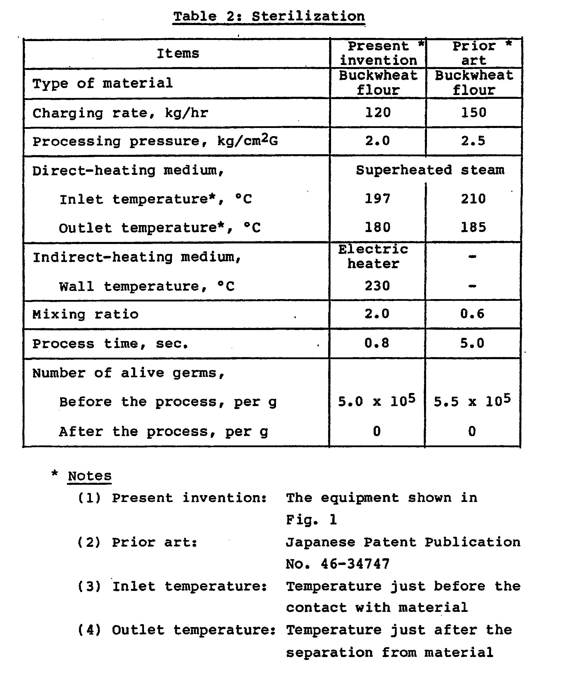
- For a case in which buckwheat flour is heated to be processed, the results of an experiment are shown in Table 2 in the next page.
- As will be comprehended from Table 2, according to the present invention, the heating time can be shortened, while having like sterilization effect to the conventional method.
- For a case in which rice bran is heated to be processed, the results of an experiment are shown in Table 3 in the next but one page.
- As will be comprehended from Table 3, according to the present invention, the acid value of product can be reduced without reducing the lipid of material.
- Incidentally, the acid value was determined by an ordinary measurement method.
- For the same case as above, also the vitamin content of product was measured. The results of this measurement are shown in Table 4 in the next but two pages.
- As will be comprehended from Table 4, according to the present invention, various heating processes such as for sterilization can be executed, without decreasing so much of vitamins present in material.
- Incidentally, for the measurement of vitamins, the following methods were employed:
- Vitamin measurement methods
- 1. Vitamin B1: Thiochrome fluorescence method
- 2. Vitamin Bz: Lumi-flavin fluorescence method
- 3. Vitamin Bs: Microbiological measurement method
- 4. Vitamin E: Liquid chromatography
- 5. Niacin: Microbiological quantitation method
 As will be understood from the foregoing description, according to the present invention, which is of such a system that in comparison with conventional art the flow rate of a direct-heating medium is decreased by combination of direct heating and indirect heating, individual equipments such as a heating tube and a cyclone can be small-sized, in addition to that sufficient economy is expectable even when following what is called one-pass system in which a direct-heating medium is wasted.
- Moreover, it also is possible to shorten the heating time, thus permitting useful ingredients in various materials, such as vitamins for example, to survive in a sufficient proportion even when such material is processed by heating.
- Further, also in the case of those materials containing lipids, the acid value can be decreased, while leaving a notable proportion of the lipids as they are.
- Hereinbelow, there will be given a number of process examples performed by use of a heating process equipment according to the present invention.
- First, description will be made of process examples 1 to 4 intended for sterilization. The heating process equipment employed was as shown in Fig. 1 (hereinbelow also, like parts are referenced by like reference numerals), and there was a single heating stage consisting of a
heating tube 4 of a 60-mm inside diameter and a 6-m length. Thirtyswirlers 403 were arranged at intervals of 20 cm. As a product discharge mechanism, there was employed anozzle 5 of the type shown in Fig. 2, which was 9.5 mm in inside diameter. Further, as an indirect-heating implement, an electric heater of a 10 kW rating was provided by uniformly coiling a heating element thereof on theheating tube 4. - Raw rice bran as material, 12 mesh or smaller in grain size and 12.0 wt% in water content, was charged at a rate of 100 kg/hr into the
heating tube 4, through whichsuperheated steam 2 kg/cm2G and 194 °C was being conducted. With surface temperature at the outside of wall of theheating tube 4 held at 240 °C in average, the material was heated, while whirling, in thetube 4 for approximately 0.7 seconds, before discharging under atmospheric pressure. At the stage of discharge, the temperature of superheated steam was 173 °C at the outlet of theheating tube 4, while the consumption of superheated steam was 60 kg/hr. - The number of alive germs per gram, which was 4.2 x 10⁶ before the heating process, became 6 after the process, and also the water content was decreased to 5.2 wt%.
- Adlay as material, fully granular and of a 7.5-wt% water content, was charged as material at a rate of 130 kg/hr into the
heating tube 4, through whichsuperheated steam 2 kg/cm2G and 200 °C was being conducted. With surface temeprature at the outside of wall of theheating tube 4 held at 250 °C in average, the material was heated, while whirling, in thetube 4 for approximately 0.8 seconds, before discharging under atmospheric pressure. At the stage of discharge, the temperature of superheated steam was 160 °C at the outlet of theheating tube 4, while the consumption of superheated steam was 70 kg/hr. - The number of alive germs per gram, which was 8.1 x 10⁵ before the heating process, became 20 after the process, and also the water content was decreased to 6.0 wt%.
- Rice chaff as material, 10 mesh or smaller in grain size and 13.0 wt% in water content, was charged at a rate of 150 kg/hr into the
heating tube 4, through whichsuperheated steam 2 kg/cm 2G and 200 °C was being conducted. With surface temperature at the outside of wall of theheating tube 4 held at 245 °C in average, the material was heated, while whirling, in thetube 4 for approximately 0.8 seconds, before discharging under atmospheric pressure. At the stage of discharge, the temperature of superheated steam was 160 °C at the outlet of theheating tube 4, while the consumption of superheated steam was 65 kg/hr. - The number of alive germs per gram, which was 5.0 x 10⁶ before the heating process, became 6 x 10 after the process, and also the water content was decreased to 3.5 wt%.
- Marine alga as material, 150 mesh or smaller in grain size and 12.5 wt% in water content, was charged at a rate of 120 kg/hr into the
heating tube 4, through which superheated steam 2.0 kg/cm2G and 200 °C was being conducted. With surface temeprature at the outside of wall of theheating tube 4 held at 250 °C in average, the material was heated, while whirling, in thetube 4 for approximately 0.8 seconds, before discharging under atmospheric pressure. At the stage of discharge, the temperature of superheated steam was 175 °C at the outlet of theheating tube 4, while the consumption of superheated steam was 70 kg/hr. - The number of alive germs per gram, which was 5.3 x 10³ before the heating process, became 20 after the process, and also the water content was decreased to 9 wt%.
- Next, description will be made of process examples 5 to 8 intended for denaturalization. The heating process equipment employed was as shown in Fig. 7 (hereinbelow as well, like parts are referenced by like reference numerals), and a heating stage consisting of a
heating tube 4 of a 60-mm inside diameter and a 6-m length was rendered triple, while having a direct-heating medium let to run in a one-pass manner. Ninety swirlers 43 were arranged at intervals of 20 cm. To constitute a three-staged product discharge mechanism, there were employednozzles 5 of the type shown in Fig. 2, of which inside diameter was 7.0 mm at a first stage, 10.0 mm at a second stage, and 14.5 mm at a third stage. Further, as an indirect-heating implement of each heating stage, an electric heater of a 10 kW rating was provided by uniformly coiling a heating element thereof on theheating tube 4. - De-fatted soybeans as material, 16 to 243 mesh in grain size and 11.0 wt% in water content, were charged at a rate of 300 kg/hr into the
heating tube 4 of first heating stage, through which superheated steam was being conducted as the direct-heating medium. Then, the material was heated to be processed, at theheating tube 4 of second heating stage and in turn at that of third heating stage, before discharging under atmospheric pressure. There was resulted a product of 95-% digestion rate and a 7.5- wt% water content. - Of superheated steam, the temperatures at the inlet and the outlet of the
heating tube 4 and the pressure therein were 220 °C, 200 °C and 6.0 kg/cm2G at the first heating stage, 200 °C, 190 °C and 3.4 kg/cm2G at the second heating stage, and 190 °C, 185 °C and 1.8 kg/cm2G at the third heating stage, respectively, while the steam consumption was 100 kg/hr and the heating time was approximately 2 seconds. - Grushed wheat as material, 12 to 60 mesh in grain size and 12.1 wt% in water content, were charged at a rate of 250 kg/hr into the
heating tube 4 of first heating stage, through which superheated steam was being conducted as the direct-heating medium. Then, the material was heated to be processed, at theheating tube 4 of second heating stage and in turn at that of third heating stage, before discharging under atmospheric pressure. There was resulted a product of a digestion rate of 94.3 %, a conversion of 73.0 % to a-starch, and a water content of 8 wt%. - Incidentally, the conversion in terms of % to a-starch was determined in the following way: 0.5 g of the sample as finely ground was accurately weighed out, then dispersed in 40 ml of water, admixed with 20 ml of 2-N acetate buffer (pH 4.8), and left standing at 37 °C. To the mixture was then added 5 ml of an enzyme solution prepared by dissolving 0.6 g of an Endomyces, enzyme (saccharogenic amylase) (Matsurase M-00; Matsutani Kagaku Co.) in 250 ml of 0.008-M acetate buffer. The mixture was allowed to react for one hour and the reaction was terminated with 4 ml of 2-N sodium hydroxide solution. The reaction mixture was made up to 100 ml with water, filtered through Toyo filter paper No. 5A, and the filtrate was assayed for reducing sugar by the SOMOGYI method. The control experiment was run by by accurately weighing out 0.5 g of the same sample, dispersing the sample in 40 ml of water, admixing with 5 ml of 2-N sodium hydroxide solution to effect complete conversion (100 %) to a-starch, neutralyzing the converted solution, allowing the neutralized solution to react with the same enzyme solution as used above, and assaying the reaction mixture for reducing sugar. The percentage conversion to a-starch was calculated by the following equation:
- Conversion (%) to a-starch
- = [(reducing sugar in sample)/(reducing sugar in the control)] x 100.
- Of superheated steam, the temperatures at the inlet and the outlet of the
heating tube 4 and the pressure therein were 250 °C, 210 °C and 6.0 kg/cm2G at the first heating stage, 210 °C, 190 °C and 3.3 kg/cm2G at the second heating stage, and 190 °C, 180 °C and 1.8 kg/cm2G at the third heating stage, respectively, while the steam consumption was 100 kg/hr and the heating time was approximately 2 seconds. - Polished rice as material, fully granular and of a 13.0-wt% water content, were charged at a rate of 300 kg/hr into the
heating tube 4 of first heating stage, through which superheated steam was being conducted as the direct-heating medium. Then, the material was heated to be processed, at theheating tube 4 of second heating stage and in turn at that of third heating stage, before discharging under atmospheric pressure. There was resulted a product of a conversion of 90 % to a-starch and a water content of 8.5 wt% - Of superheated steam, the temperatures at the inlet and the outlet of the
heating tube 4 and the pressure therein were 220 °C, 200 °C and 4.0 kg/cM 2G at the first heating stage, 200 °C, 180 °C and 2.7 kg/cm2G at the second heating stage, and 180 °C, 170 °C and 1.5 kg/cm2G at the third heating stage, respectively, while the steam consumption was 80 kg/hr and the heating time was approximately 2 seconds. - Ground corn as material, 6 to 42 mesh in grain size and 10.5 wt% in water content, were charged at a rate of 250 kg/hr into the
heating tube 4 of first heating stage, through which superheated steam was being conducted as the direct-heating medium. Then, the material was heated to be processed, at theheating tube 4 of second heating stage and in turn at that of third heating stage, before discharging under atmospheric pressure. There was resulted a product of a conversion of 75 % to a-starch, and a water content of 9.5 wt%. - Of superheated steam, the temperatures at the inlet and the outlet of the
heating tube 4 and the pressure therein were 250 °C, 220 °C and 6.0 kg/cM 2G at the first heating stage, 220 °C, 190 °C and 4.0 kg/cm2G at the second heating stage, and 190 °C, 175 °C and 2.8 kg/cm2G at the third heating stage, respectively, while the steam consumption was 100 kg/hr and the heating time was approximately 2 seconds.
Claims (16)
Applications Claiming Priority (2)
| Application Number | Priority Date | Filing Date | Title |
|---|---|---|---|
| JP39698/85 | 1985-02-28 | ||
| JP60039698A JPS61199819A (en) | 1985-02-28 | 1985-02-28 | Heat treatment method and apparatus |
Publications (3)
| Publication Number | Publication Date |
|---|---|
| EP0196464A2 EP0196464A2 (en) | 1986-10-08 |
| EP0196464A3 EP0196464A3 (en) | 1988-03-30 |
| EP0196464B1 true EP0196464B1 (en) | 1990-12-27 |
Family
ID=12560237
Family Applications (1)
| Application Number | Title | Priority Date | Filing Date |
|---|---|---|---|
| EP86102611A Expired - Lifetime EP0196464B1 (en) | 1985-02-28 | 1986-02-28 | Method of processing by heating a powdery and/or granular substance, and apparatus therefor |
Country Status (4)
| Country | Link |
|---|---|
| US (1) | US4709487A (en) |
| EP (1) | EP0196464B1 (en) |
| JP (1) | JPS61199819A (en) |
| DE (1) | DE3676526D1 (en) |
Families Citing this family (31)
| Publication number | Priority date | Publication date | Assignee | Title |
|---|---|---|---|---|
| US4911889A (en) * | 1987-09-16 | 1990-03-27 | The Procter & Gamble Company | Methods for sanitizing materials utilizing superheated steam |
| US5229117A (en) * | 1987-09-16 | 1993-07-20 | The Procter & Gamble Company | Methods and apparatus for sanitizing materials utilizing superheated steam |
| JP2637530B2 (en) * | 1988-12-29 | 1997-08-06 | ハウス食品株式会社 | Superheated steam sterilizer |
| FR2656547B1 (en) * | 1989-12-29 | 1992-04-10 | Cogat Pierre Olivier | CONTINUOUS APPARATUS FOR DEAERING, HEATING, MAINTAINING TEMPERATURE, COOLING SOLID ORGANIC MATERIALS IN VACUUM. |
| CH680341A5 (en) * | 1991-05-04 | 1992-08-14 | Kurt Weber | |
| EP0780056A1 (en) * | 1995-12-22 | 1997-06-25 | Societe Des Produits Nestle S.A. | Apparatus and method for treating a fluid product |
| SE507856C2 (en) | 1996-04-12 | 1998-07-20 | Acanova Ab | Heat remediation of seeds |
| ES2172628T3 (en) * | 1996-06-04 | 2002-10-01 | Nestle Sa | CONTINUOUS GRAIN COOKING. |
| US6086935A (en) * | 1998-05-19 | 2000-07-11 | Cargill, Incorporated | Method for the reduction of microbial level in cereal and legume products |
| US6613371B2 (en) | 1997-07-23 | 2003-09-02 | Cargill, Incorporated | Method for malting seeds |
| DE19812963C1 (en) * | 1998-03-24 | 1999-08-19 | Bullemer | Steam disinfecting assembly for bulk solids has steam jet driving |
| US6383547B1 (en) | 1998-05-12 | 2002-05-07 | Cargill, Incorporated | Process for preparing aspirated bran as a flour additive |
| US6610349B1 (en) | 1998-05-15 | 2003-08-26 | Cargill, Incorporated | Milled cereal by-product which is an additive for increasing total dietary fiber |
| US6033709A (en) * | 1998-08-20 | 2000-03-07 | Cargill, Incorporated | Process for the production of partially gelatinized rice flour |
| US6068873A (en) * | 1998-08-20 | 2000-05-30 | Cargill, Incorporated | Process for the production of masa flour |
| FI109964B (en) * | 1998-11-02 | 2002-11-15 | Lp Tutkimuskeskus Oy | Method and apparatus for the treatment of cereal grains |
| SE515943C2 (en) * | 2000-01-31 | 2001-10-29 | Arom Pak Internat Ab | Device and method for killing microorganisms in a fluid product stream |
| NL1014900C2 (en) * | 2000-04-10 | 2001-10-11 | Siersema Scheffers B V | Method and device for the heat treatment of a heat-sensitive liquid. |
| DE10203190A1 (en) * | 2002-01-25 | 2003-08-07 | Buehler Ag | Process to sterilize natural products such as seeds, dried fruit, root crops and cocoa beans in steam reactor |
| WO2004049825A1 (en) * | 2002-12-05 | 2004-06-17 | Valentin Meltser | Method for heat treating cereals and installation for the implementation thereof |
| NL1022547C2 (en) * | 2003-01-31 | 2004-08-03 | Tno | Method for roasting a food and a food obtainable with the method. |
| NL1022693C2 (en) * | 2003-02-14 | 2004-08-17 | Tno | Continuous thermal process for treating coarse food particles and food particles that are available with the process according to the invention. |
| SE524749C2 (en) * | 2003-02-27 | 2004-09-28 | Tetra Laval Holdings & Finance | Method and apparatus for a steam injector |
| GB2402865B (en) * | 2003-06-16 | 2006-02-15 | Clive Edward Jewers | De-Infestation method and apparatus |
| US20070234589A1 (en) * | 2006-04-05 | 2007-10-11 | Peter Bernegger | Pressurized Drying/Dehydration Apparatus and Method |
| JP2006212038A (en) * | 2006-04-28 | 2006-08-17 | Sharp Corp | Separation method and separator |
| JP4722011B2 (en) * | 2006-10-31 | 2011-07-13 | サントリーホールディングス株式会社 | Process for producing processed pearl barley |
| BRPI0913223B1 (en) | 2008-05-26 | 2021-05-11 | Fujiwara Techno-Art Co., Ltd | method for sterilizing powder or grain |
| US20150250212A1 (en) * | 2012-09-26 | 2015-09-10 | Nederlandse Organisatie Voor Toegepast- Natuurwetenschappelijk Onderzoek Tno | New foods with modified cereal bran and methods for producing these |
| JP7063948B2 (en) * | 2020-07-13 | 2022-05-17 | 電気興業株式会社 | Superheated steam reactor |
| CN115472069B (en) * | 2022-09-08 | 2025-03-07 | 华能山东发电有限公司 | An intelligent powder spraying simulation system for coal-fired boilers |
Family Cites Families (18)
| Publication number | Priority date | Publication date | Assignee | Title |
|---|---|---|---|---|
| GB191101260A (en) * | 1910-05-12 | 1911-04-20 | August John Koegler | Improvement in Agitators for Grain Heaters. |
| FR1020798A (en) * | 1949-06-27 | 1953-02-10 | Ursina A G | Sterilization of liquids |
| CH306359A (en) * | 1952-09-12 | 1955-04-15 | Ag Alpura | Device for sterilizing liquids. |
| US3068584A (en) * | 1957-07-12 | 1962-12-18 | Ruhrchemie Ag | Process for the treatment of divided materials |
| GB1034722A (en) * | 1964-02-28 | 1966-07-06 | George Scott & Son London Ltd | Apparatus for heat or cold treating material under pressure |
| GB1310507A (en) * | 1969-05-28 | 1973-03-21 | Apv Co Ltd | Heat treatment of flowable solids |
| US3754926A (en) * | 1970-07-27 | 1973-08-28 | Gen Mills Inc | Method for texturizing protein material |
| GB1313281A (en) * | 1971-01-14 | 1973-04-11 | Apv Co Ltd | Heat treatment of solids-bearing liquids |
| AU464080B2 (en) * | 1972-05-19 | 1975-08-14 | Archibald Donald Robert | Sterilizing food compositions |
| US3955486A (en) * | 1973-08-24 | 1976-05-11 | General Mills, Inc. | Food processing apparatus |
| GB1574808A (en) * | 1976-06-09 | 1980-09-10 | In Da Te Ag | Steam injectors |
| JPS5423971A (en) * | 1977-07-26 | 1979-02-22 | Oki Electric Ind Co Ltd | Method of plating connector for print wire board |
| JPS5524865A (en) * | 1978-08-09 | 1980-02-22 | Yamaha Motor Co Ltd | Method of finishing grinding of brake pannel for drum brake |
| JPS584467Y2 (en) * | 1978-10-18 | 1983-01-25 | 雪印乳業株式会社 | High concentration liquid sterilizer |
| JPS5743656A (en) * | 1980-08-27 | 1982-03-11 | Masakichi Kawahara | Indirect heating kettle for steaming and boiling of "go" of "tofu" without using defoaming agent |
| DE3261422D1 (en) * | 1981-03-19 | 1985-01-17 | Kikkoman Corp | Method for preparing spices |
| JPS5842743A (en) * | 1981-09-04 | 1983-03-12 | Mitsubishi Metal Corp | Cast ni alloy for guide shoe of inclined hot rolling mill for manufacturing seamless steel pipe |
| DE3271831D1 (en) * | 1982-05-19 | 1986-07-31 | Kikkoman Corp | Method and apparatus for heat-treating powdered, granular and like materials |
-
1985
- 1985-02-28 JP JP60039698A patent/JPS61199819A/en active Granted
-
1986
- 1986-02-28 EP EP86102611A patent/EP0196464B1/en not_active Expired - Lifetime
- 1986-02-28 DE DE8686102611T patent/DE3676526D1/en not_active Expired - Lifetime
- 1986-02-28 US US06/834,928 patent/US4709487A/en not_active Expired - Lifetime
Also Published As
| Publication number | Publication date |
|---|---|
| US4709487A (en) | 1987-12-01 |
| JPS61199819A (en) | 1986-09-04 |
| DE3676526D1 (en) | 1991-02-07 |
| JPH0553B2 (en) | 1993-01-05 |
| EP0196464A3 (en) | 1988-03-30 |
| EP0196464A2 (en) | 1986-10-08 |
Similar Documents
| Publication | Publication Date | Title |
|---|---|---|
| US4709487A (en) | Method for processing by heating and equipment for same | |
| CN104994754B (en) | Methods for extruding powered nutritional products using a high shear element | |
| CN104869850B (en) | Extrusion nutrient powder with improved stability of emulsion and dispersiveness and preparation method thereof | |
| BR8606972A (en) | PERFECTED SYSTEM AND PROCESS FOR THE CONDITIONING OF PARTICULATED MATERIAL, AND PERFECTED SYSTEM FOR THE TREATMENT OF GRAINS FOR THE CONDITIONING OF GRAINS AND ITS MICROINGREDIENTS WITH HEAT AND HUMIDITY BEFORE PELLETIZATION | |
| EP3250049B1 (en) | Process for improving the organoleptic and nutritional properties of legume meal and components and derivatives thereof | |
| CN108740350A (en) | A kind of composite feed additive and its application | |
| KR101150814B1 (en) | Granulated powder for thin rice gruel and preparation method thereof | |
| EP0094448B1 (en) | Method and apparatus for heat-treating powdered, granular and like materials | |
| EP1732405B1 (en) | Extrusion-stable poly-unsaturated fatty-acid compositions for food products | |
| JP3941903B2 (en) | Continuous stirring and sterilizing equipment for powder | |
| WO2004044215A2 (en) | Formulations comprising vitamin b12, method of production and use thereof | |
| JPH10127737A (en) | Ultraviolet sterilizer | |
| JPS58165744A (en) | Heat treatment of powdery or granular substance and its device | |
| Tymchak et al. | Production of popped Sorghum with using microwave treatment | |
| JPS6152657B2 (en) | ||
| US20080134539A1 (en) | Apparatus and Method for Grain Treatment | |
| Liang et al. | Extrusion cooking of rapeseed meal for feeding value improvement | |
| JPS58111667A (en) | Method and apparatus for heat-treatment of granular substance | |
| CN1163703A (en) | Nutritive health flour | |
| CN219422070U (en) | Konjaku flour ultraviolet sterilization device | |
| PL241745B1 (en) | Line for production of a food product from a granular material, especially cereal grains in the form of flakes, and method for producing the food product | |
| CN107950791A (en) | A kind of mixed fodder for being conducive to domestic pig absorption | |
| CN212549107U (en) | A PLC-controlled buckwheat extract functional food preparation device | |
| US10967345B2 (en) | Multiple modular system for the formation of particles in powder and microcapsule form for different processes | |
| JP2008017784A (en) | Seed powder and method for producing the same |
Legal Events
| Date | Code | Title | Description |
|---|---|---|---|
| PUAI | Public reference made under article 153(3) epc to a published international application that has entered the european phase |
Free format text: ORIGINAL CODE: 0009012 |
|
| AK | Designated contracting states |
Kind code of ref document: A2 Designated state(s): DE FR GB NL |
|
| PUAL | Search report despatched |
Free format text: ORIGINAL CODE: 0009013 |
|
| AK | Designated contracting states |
Kind code of ref document: A3 Designated state(s): DE FR GB NL |
|
| 17P | Request for examination filed |
Effective date: 19880620 |
|
| 17Q | First examination report despatched |
Effective date: 19890908 |
|
| GRAA | (expected) grant |
Free format text: ORIGINAL CODE: 0009210 |
|
| AK | Designated contracting states |
Kind code of ref document: B1 Designated state(s): DE FR GB NL |
|
| REF | Corresponds to: |
Ref document number: 3676526 Country of ref document: DE Date of ref document: 19910207 |
|
| ET | Fr: translation filed | ||
| PLBE | No opposition filed within time limit |
Free format text: ORIGINAL CODE: 0009261 |
|
| STAA | Information on the status of an ep patent application or granted ep patent |
Free format text: STATUS: NO OPPOSITION FILED WITHIN TIME LIMIT |
|
| 26N | No opposition filed | ||
| PGFP | Annual fee paid to national office [announced via postgrant information from national office to epo] |
Ref country code: DE Payment date: 19940201 Year of fee payment: 9 |
|
| PGFP | Annual fee paid to national office [announced via postgrant information from national office to epo] |
Ref country code: GB Payment date: 19940221 Year of fee payment: 9 |
|
| PGFP | Annual fee paid to national office [announced via postgrant information from national office to epo] |
Ref country code: FR Payment date: 19940224 Year of fee payment: 9 |
|
| PGFP | Annual fee paid to national office [announced via postgrant information from national office to epo] |
Ref country code: NL Payment date: 19940228 Year of fee payment: 9 |
|
| PG25 | Lapsed in a contracting state [announced via postgrant information from national office to epo] |
Ref country code: GB Effective date: 19950228 |
|
| PG25 | Lapsed in a contracting state [announced via postgrant information from national office to epo] |
Ref country code: NL Effective date: 19950901 |
|
| GBPC | Gb: european patent ceased through non-payment of renewal fee |
Effective date: 19950228 |
|
| PG25 | Lapsed in a contracting state [announced via postgrant information from national office to epo] |
Ref country code: FR Effective date: 19951031 |
|
| NLV4 | Nl: lapsed or anulled due to non-payment of the annual fee |
Effective date: 19950901 |
|
| PG25 | Lapsed in a contracting state [announced via postgrant information from national office to epo] |
Ref country code: DE Effective date: 19951101 |
|
| REG | Reference to a national code |
Ref country code: FR Ref legal event code: ST |