EP0195880A2 - A sliding door structure - Google Patents
A sliding door structure Download PDFInfo
- Publication number
- EP0195880A2 EP0195880A2 EP85830243A EP85830243A EP0195880A2 EP 0195880 A2 EP0195880 A2 EP 0195880A2 EP 85830243 A EP85830243 A EP 85830243A EP 85830243 A EP85830243 A EP 85830243A EP 0195880 A2 EP0195880 A2 EP 0195880A2
- Authority
- EP
- European Patent Office
- Prior art keywords
- door
- bracket
- fact
- sliding door
- doors
- Prior art date
- Legal status (The legal status is an assumption and is not a legal conclusion. Google has not performed a legal analysis and makes no representation as to the accuracy of the status listed.)
- Granted
Links
Images


Classifications
-
- E—FIXED CONSTRUCTIONS
- E05—LOCKS; KEYS; WINDOW OR DOOR FITTINGS; SAFES
- E05D—HINGES OR SUSPENSION DEVICES FOR DOORS, WINDOWS OR WINGS
- E05D15/00—Suspension arrangements for wings
- E05D15/06—Suspension arrangements for wings for wings sliding horizontally more or less in their own plane
- E05D15/10—Suspension arrangements for wings for wings sliding horizontally more or less in their own plane movable out of one plane into a second parallel plane
- E05D15/1042—Suspension arrangements for wings for wings sliding horizontally more or less in their own plane movable out of one plane into a second parallel plane with transversely moving carriage
-
- E—FIXED CONSTRUCTIONS
- E06—DOORS, WINDOWS, SHUTTERS, OR ROLLER BLINDS IN GENERAL; LADDERS
- E06B—FIXED OR MOVABLE CLOSURES FOR OPENINGS IN BUILDINGS, VEHICLES, FENCES OR LIKE ENCLOSURES IN GENERAL, e.g. DOORS, WINDOWS, BLINDS, GATES
- E06B3/00—Window sashes, door leaves, or like elements for closing wall or like openings; Layout of fixed or moving closures, e.g. windows in wall or like openings; Features of rigidly-mounted outer frames relating to the mounting of wing frames
- E06B3/32—Arrangements of wings characterised by the manner of movement; Arrangements of movable wings in openings; Features of wings or frames relating solely to the manner of movement of the wing
- E06B3/50—Arrangements of wings characterised by the manner of movement; Arrangements of movable wings in openings; Features of wings or frames relating solely to the manner of movement of the wing with more than one kind of movement
- E06B3/5045—Arrangements of wings characterised by the manner of movement; Arrangements of movable wings in openings; Features of wings or frames relating solely to the manner of movement of the wing with more than one kind of movement specially adapted for furniture
-
- E—FIXED CONSTRUCTIONS
- E05—LOCKS; KEYS; WINDOW OR DOOR FITTINGS; SAFES
- E05D—HINGES OR SUSPENSION DEVICES FOR DOORS, WINDOWS OR WINGS
- E05D15/00—Suspension arrangements for wings
- E05D15/06—Suspension arrangements for wings for wings sliding horizontally more or less in their own plane
- E05D15/10—Suspension arrangements for wings for wings sliding horizontally more or less in their own plane movable out of one plane into a second parallel plane
- E05D2015/1028—Suspension arrangements for wings for wings sliding horizontally more or less in their own plane movable out of one plane into a second parallel plane with only the wing moving transversely
- E05D2015/1039—Suspension arrangements for wings for wings sliding horizontally more or less in their own plane movable out of one plane into a second parallel plane with only the wing moving transversely the wing sliding transversely on the carriage
-
- E—FIXED CONSTRUCTIONS
- E05—LOCKS; KEYS; WINDOW OR DOOR FITTINGS; SAFES
- E05F—DEVICES FOR MOVING WINGS INTO OPEN OR CLOSED POSITION; CHECKS FOR WINGS; WING FITTINGS NOT OTHERWISE PROVIDED FOR, CONCERNED WITH THE FUNCTIONING OF THE WING
- E05F1/00—Closers or openers for wings, not otherwise provided for in this subclass
- E05F1/08—Closers or openers for wings, not otherwise provided for in this subclass spring-actuated, e.g. for horizontally sliding wings
- E05F1/16—Closers or openers for wings, not otherwise provided for in this subclass spring-actuated, e.g. for horizontally sliding wings for sliding wings
-
- E—FIXED CONSTRUCTIONS
- E05—LOCKS; KEYS; WINDOW OR DOOR FITTINGS; SAFES
- E05Y—INDEXING SCHEME RELATING TO HINGES OR OTHER SUSPENSION DEVICES FOR DOORS, WINDOWS OR WINGS AND DEVICES FOR MOVING WINGS INTO OPEN OR CLOSED POSITION, CHECKS FOR WINGS AND WING FITTINGS NOT OTHERWISE PROVIDED FOR, CONCERNED WITH THE FUNCTIONING OF THE WING
- E05Y2201/00—Constructional elements; Accessories therefore
- E05Y2201/40—Motors; Magnets; Springs; Weights; Accessories therefore
- E05Y2201/404—Motors; Magnets; Springs; Weights; Accessories therefore characterised by the function
- E05Y2201/41—Motors; Magnets; Springs; Weights; Accessories therefore characterised by the function for closing
- E05Y2201/412—Motors; Magnets; Springs; Weights; Accessories therefore characterised by the function for closing for the final closing movement
-
- E—FIXED CONSTRUCTIONS
- E05—LOCKS; KEYS; WINDOW OR DOOR FITTINGS; SAFES
- E05Y—INDEXING SCHEME RELATING TO HINGES OR OTHER SUSPENSION DEVICES FOR DOORS, WINDOWS OR WINGS AND DEVICES FOR MOVING WINGS INTO OPEN OR CLOSED POSITION, CHECKS FOR WINGS AND WING FITTINGS NOT OTHERWISE PROVIDED FOR, CONCERNED WITH THE FUNCTIONING OF THE WING
- E05Y2201/00—Constructional elements; Accessories therefore
- E05Y2201/40—Motors; Magnets; Springs; Weights; Accessories therefore
- E05Y2201/47—Springs; Spring tensioners
- E05Y2201/488—Traction springs
-
- E—FIXED CONSTRUCTIONS
- E05—LOCKS; KEYS; WINDOW OR DOOR FITTINGS; SAFES
- E05Y—INDEXING SCHEME RELATING TO HINGES OR OTHER SUSPENSION DEVICES FOR DOORS, WINDOWS OR WINGS AND DEVICES FOR MOVING WINGS INTO OPEN OR CLOSED POSITION, CHECKS FOR WINGS AND WING FITTINGS NOT OTHERWISE PROVIDED FOR, CONCERNED WITH THE FUNCTIONING OF THE WING
- E05Y2201/00—Constructional elements; Accessories therefore
- E05Y2201/60—Suspension or transmission members; Accessories therefore
- E05Y2201/604—Transmission members
-
- E—FIXED CONSTRUCTIONS
- E05—LOCKS; KEYS; WINDOW OR DOOR FITTINGS; SAFES
- E05Y—INDEXING SCHEME RELATING TO HINGES OR OTHER SUSPENSION DEVICES FOR DOORS, WINDOWS OR WINGS AND DEVICES FOR MOVING WINGS INTO OPEN OR CLOSED POSITION, CHECKS FOR WINGS AND WING FITTINGS NOT OTHERWISE PROVIDED FOR, CONCERNED WITH THE FUNCTIONING OF THE WING
- E05Y2201/00—Constructional elements; Accessories therefore
- E05Y2201/60—Suspension or transmission members; Accessories therefore
- E05Y2201/606—Accessories therefore
- E05Y2201/62—Synchronisation of transmission members
-
- E—FIXED CONSTRUCTIONS
- E05—LOCKS; KEYS; WINDOW OR DOOR FITTINGS; SAFES
- E05Y—INDEXING SCHEME RELATING TO HINGES OR OTHER SUSPENSION DEVICES FOR DOORS, WINDOWS OR WINGS AND DEVICES FOR MOVING WINGS INTO OPEN OR CLOSED POSITION, CHECKS FOR WINGS AND WING FITTINGS NOT OTHERWISE PROVIDED FOR, CONCERNED WITH THE FUNCTIONING OF THE WING
- E05Y2201/00—Constructional elements; Accessories therefore
- E05Y2201/60—Suspension or transmission members; Accessories therefore
- E05Y2201/622—Suspension or transmission members elements
- E05Y2201/624—Arms
- E05Y2201/626—Levers
-
- E—FIXED CONSTRUCTIONS
- E05—LOCKS; KEYS; WINDOW OR DOOR FITTINGS; SAFES
- E05Y—INDEXING SCHEME RELATING TO HINGES OR OTHER SUSPENSION DEVICES FOR DOORS, WINDOWS OR WINGS AND DEVICES FOR MOVING WINGS INTO OPEN OR CLOSED POSITION, CHECKS FOR WINGS AND WING FITTINGS NOT OTHERWISE PROVIDED FOR, CONCERNED WITH THE FUNCTIONING OF THE WING
- E05Y2201/00—Constructional elements; Accessories therefore
- E05Y2201/60—Suspension or transmission members; Accessories therefore
- E05Y2201/622—Suspension or transmission members elements
- E05Y2201/64—Carriers
-
- E—FIXED CONSTRUCTIONS
- E05—LOCKS; KEYS; WINDOW OR DOOR FITTINGS; SAFES
- E05Y—INDEXING SCHEME RELATING TO HINGES OR OTHER SUSPENSION DEVICES FOR DOORS, WINDOWS OR WINGS AND DEVICES FOR MOVING WINGS INTO OPEN OR CLOSED POSITION, CHECKS FOR WINGS AND WING FITTINGS NOT OTHERWISE PROVIDED FOR, CONCERNED WITH THE FUNCTIONING OF THE WING
- E05Y2201/00—Constructional elements; Accessories therefore
- E05Y2201/60—Suspension or transmission members; Accessories therefore
- E05Y2201/622—Suspension or transmission members elements
- E05Y2201/686—Rods, links
-
- E—FIXED CONSTRUCTIONS
- E05—LOCKS; KEYS; WINDOW OR DOOR FITTINGS; SAFES
- E05Y—INDEXING SCHEME RELATING TO HINGES OR OTHER SUSPENSION DEVICES FOR DOORS, WINDOWS OR WINGS AND DEVICES FOR MOVING WINGS INTO OPEN OR CLOSED POSITION, CHECKS FOR WINGS AND WING FITTINGS NOT OTHERWISE PROVIDED FOR, CONCERNED WITH THE FUNCTIONING OF THE WING
- E05Y2800/00—Details, accessories and auxiliary operations not otherwise provided for
- E05Y2800/10—Additional functions
- E05Y2800/102—Additional wing movements
-
- E—FIXED CONSTRUCTIONS
- E05—LOCKS; KEYS; WINDOW OR DOOR FITTINGS; SAFES
- E05Y—INDEXING SCHEME RELATING TO HINGES OR OTHER SUSPENSION DEVICES FOR DOORS, WINDOWS OR WINGS AND DEVICES FOR MOVING WINGS INTO OPEN OR CLOSED POSITION, CHECKS FOR WINGS AND WING FITTINGS NOT OTHERWISE PROVIDED FOR, CONCERNED WITH THE FUNCTIONING OF THE WING
- E05Y2900/00—Application of doors, windows, wings or fittings thereof
- E05Y2900/20—Application of doors, windows, wings or fittings thereof for furnitures, e.g. cabinets
Definitions
- the present invention relates generally to a sliding door structure and particularly to a sliding door structure suitable for furniture and the like.
- the present invention seeks to eliminate the above mentioned disadvantages by providing a sliding door structure suitable for furniture and the like which will allow the possibility of having two or more sliding doors for closing the front face of an item of furniture, which doors can be disposed in a coplanar position with respect to one another in the closure position in such a way as to provide surface continuity over the front face of the furniture.
- a sliding door structure comprising at least a first door and a second door, respectively slidable on a pair of upper guides and a pair of lower guides which are parallel to and spaced from one another, characterised by the fact that the said first door is connected to rollers movable on the guides, with the interposition of a linking mechanism which positions the said first door substantially coplanar with the second door in the closure position and allows displacement of the first door transversely with respect to the direction of translation of the doors during their opening or closing movement to superimpose the first door over the second door when the doors are open.
- the present invention thus offers the advantage of a sliding door structure for furniture and the like which permits the doors to be coplanar with one another in the closure position and for this coplanar position to be reached in an automatic manner without the need for complex mechanisms.
- Another advantage of the present invention is that it provides a sliding door structure in which the relative movement between the doors, from the coplanar position to the position where the planes in which they lie are offset from one another, takes place simply by the interference of the doors with one another without having to require any particular actuation on the part of theteil. The full movement thus takes place with only a simple opening or closing motion by the user.
- the least advantage of the present invention is that it is capable of providing a sliding door structure for furniture and the like which is of rapid and simple assembly and which, moreover, is not subject to jamming or damage of any type.
- the sliding door structure for furniture and the like comprises at least one first door indicated 1, and at least one second door indicated 2, which are advantageously constituted by a flat panel of wood or other suitable material.
- the first door 1 is connected, by means of a mechanism which will be described in more detail below, to a first lower fixed guide 3 and to a first upper fixed guide 4, whilst the second door 2 is connected, in a conventional manner, to a second lower fixed guide 5 and a second upper fixed guide 6.
- the said lower fixed guides, as well as the upper fixed guides, all extend parallel to one another and are mutually spaced.
- the first door is connected indirectly to the guides 3 and 4 by a linking mechanism which is able to allow the door 1 to displaced in a direction perpendicular to the translation direction along which the door moves during opening, thus making it possible for the first and second doors to move past each other upon opening whilst it is possible to dispose the doors, automatically, coplanar with one another in the closure position.
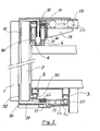
- This linking mechanism has an upper part which is shown in exploded perspective view in Figure 2, which includes a support bracket 10 having a horizontal flange 11from which extends a substantially downwardly projecting vertical flange 12 which is connected to the upper edge of the first door 1.
- a respective guide sleeve 13 into each of which engages a respective set of rollers 14 some of which have a horizontal axis and some of which have a vertical axis.
- the sets of rollers 14 are supported by respective brackets 15 which are both rigidly connected to a channel section element 16 which rotatably supports the upper rollers 17 on the first guide 4.
- each cranked thrust arm 20 which are each pivoted at their central or elbow portion 21 to a respective bracket 15 and which, at the end of a first limb 22 have an engagement roller 23 which is housed in a respective elongate slit 24 in the horizontal flange 11 of the support bracket 10.
- the other limb of each cranked thrust arm 20 is connected to an upper thrust arm displacement rod 25, which joins the thrust arms 20 together and synchronizes their movement.
- resilient biasing means which act between the support bracket 10 and the bracket 15 and which are advantageously constituted by tension springs 26 which resiliently bias the door 1 towards a position coplanar with the door 2 as will be made more clear hereinbelow.
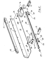
- a lower support bracket 30, shown in Figure 3 which has a horizontal flange 31 from which extends upwardly a vertical flange 32 which is fixed to the lower edge of the door itself.
- the horizontal flange 31 is fixed at each end to respective slides 33 each of which slidably couples with a respective movable guide 34 each supporting a roller 35 having a vertical axis, which slidably engages in the first fixed guide 3 ( Figure 1).
- the elbow portion of a respective cranked lower thrust arm 36 is pivoted to each movable guide 34.
- Each cranked thrust arm 36 has a first limb 37, which terminates in a pin 38 slidably connectable in a channel element 39 rigidly connected to the bracket 30, and a second limb 40 by which the lower thrust arm 36 is pivoted to a lower thrust arm displacement rod 41 which is also provided at one end with a lower ramp insert 42.
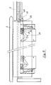
- the second door 2 is provided at its upper edge with upper guide rollers 50, which roll on the second upper guide 6 and, at its lower edge, with lower rollers 51, which engage with the second of the lower fixed guides 5.
- upper guide rollers 50 which roll on the second upper guide 6 and, at its lower edge, with lower rollers 51, which engage with the second of the lower fixed guides 5.
- thrust rollers indicated 60 Connected to the second door, at a lateral edge of the door itself, there are provided thrust rollers indicated 60, which have the function of engaging with the upper and lower thrust arm displacement rods 25 and 41 in such a way that, during opening translation of one or the other door along the door slide track, there is created a thrust which overcomes both the bias of the springs 26 provided in the upper connecting mechanism, and the bias of the springs 43 provided in the lower connecting mechanism, which causes a displacement of both the lower and upper thrust arms about their central or elbow pivots.
Abstract
Description
- The present invention relates generally to a sliding door structure and particularly to a sliding door structure suitable for furniture and the like.
- Many items of furniture currently available on the market have a front closure in the form of doors slidable along guides which extend parallel to one another. In the known sliding door structures there are generally provided two parallel, adjacent lower guides and two parallel adjacent upper guides which are closely spaced from one another and constitute guide tracks for . respective first and second doors which are, consequently, movable along paths of displacement which are parallel to but spaced from one another. This known sliding door structure is widely used and has been found to be very practical, but it has the disadvantage that in the closure position the doors lie in planes which are offset from one another which results in a step at the adjacent edges: consequently it is not possible to have smooth continuity of the front surface of the furniture, and this leads to an assymmetry which is aesthetically unsatisfactory.
- Arrangements which allow the sliding doors to be coplanar in the closure position have been sought, but the structures so far devised have been exceedingly complex and in general are prone to jamming, which reduces the practicality and reliability of the doors.
- The present invention seeks to eliminate the above mentioned disadvantages by providing a sliding door structure suitable for furniture and the like which will allow the possibility of having two or more sliding doors for closing the front face of an item of furniture, which doors can be disposed in a coplanar position with respect to one another in the closure position in such a way as to provide surface continuity over the front face of the furniture.
- According to the present invention there is provided a sliding door structure comprising at least a first door and a second door, respectively slidable on a pair of upper guides and a pair of lower guides which are parallel to and spaced from one another, characterised by the fact that the said first door is connected to rollers movable on the guides, with the interposition of a linking mechanism which positions the said first door substantially coplanar with the second door in the closure position and allows displacement of the first door transversely with respect to the direction of translation of the doors during their opening or closing movement to superimpose the first door over the second door when the doors are open.
- The present invention thus offers the advantage of a sliding door structure for furniture and the like which permits the doors to be coplanar with one another in the closure position and for this coplanar position to be reached in an automatic manner without the need for complex mechanisms.
- Another advantage of the present invention is that it provides a sliding door structure in which the relative movement between the doors, from the coplanar position to the position where the planes in which they lie are offset from one another, takes place simply by the interference of the doors with one another without having to require any particular actuation on the part of the utiliser. The full movement thus takes place with only a simple opening or closing motion by the user.
- Not the least advantage of the present invention is that it is capable of providing a sliding door structure for furniture and the like which is of rapid and simple assembly and which, moreover, is not subject to jamming or damage of any type.
- One embodiment of the present invention will now be more particularly described, by way of example with reference to the attached drawings, in which:
- Figure 1. is a schematic vertical section of a sliding door structure made according to the principles of the present invention;
- Figure 2 is an exploded perspective view of a part of the mechanism connected to the upper part of the first door;
- Figure 3 is an exploded perspective view, of part of the mechanism connected to the lower part of the first door;
- Figure 4 is a plan view of the upper part of the two doors in the closure position;
- Figure 5 is a plan view of the upper part of the two doors in a partly open position;
- Figure 6 is a plan view showing the lower part of the doors, with the doors shown in the closure position in continuous outline and in the open position in broken outline.
- Referring now to the drawings, the sliding door structure for furniture and the like comprises at least one first door indicated 1, and at least one second door indicated 2, which are advantageously constituted by a flat panel of wood or other suitable material.
- The
first door 1 is connected, by means of a mechanism which will be described in more detail below, to a first lower fixed guide 3 and to a first upperfixed guide 4, whilst thesecond door 2 is connected, in a conventional manner, to a second lowerfixed guide 5 and a second upperfixed guide 6. The said lower fixed guides, as well as the upper fixed guides, all extend parallel to one another and are mutually spaced. - The first door is connected indirectly to the
guides 3 and 4 by a linking mechanism which is able to allow thedoor 1 to displaced in a direction perpendicular to the translation direction along which the door moves during opening, thus making it possible for the first and second doors to move past each other upon opening whilst it is possible to dispose the doors, automatically, coplanar with one another in the closure position. This linking mechanism has an upper part which is shown in exploded perspective view in Figure 2, which includes asupport bracket 10 having a horizontal flange 11from which extends a substantially downwardly projectingvertical flange 12 which is connected to the upper edge of thefirst door 1. Rigidly connected adjacent each end of theflange 11 is arespective guide sleeve 13 into each of which engages a respective set ofrollers 14 some of which have a horizontal axis and some of which have a vertical axis. The sets ofrollers 14 are supported byrespective brackets 15 which are both rigidly connected to achannel section element 16 which rotatably supports theupper rollers 17 on thefirst guide 4. - To effect lateral displacement of the
bracket 10 with respect to therollers 17 there are provided cranked thrust arms generally indicated 20 which are each pivoted at their central orelbow portion 21 to arespective bracket 15 and which, at the end of afirst limb 22 have anengagement roller 23 which is housed in a respectiveelongate slit 24 in thehorizontal flange 11 of thesupport bracket 10. The other limb of eachcranked thrust arm 20 is connected to an upper thrustarm displacement rod 25, which joins thethrust arms 20 together and synchronizes their movement. There are also provided resilient biasing means which act between thesupport bracket 10 and thebracket 15 and which are advantageously constituted bytension springs 26 which resiliently bias thedoor 1 towards a position coplanar with thedoor 2 as will be made more clear hereinbelow. - At one end of the upper thrust
arm displacement rod 25 there is provided a ramp insert indicated 27, which is force fitted into the end of the rod itself. - At the lower edge of the
first door 1 it is connected to alower support bracket 30, shown in Figure 3, which has ahorizontal flange 31 from which extends upwardly avertical flange 32 which is fixed to the lower edge of the door itself. Thehorizontal flange 31 is fixed at each end torespective slides 33 each of which slidably couples with a respectivemovable guide 34 each supporting aroller 35 having a vertical axis, which slidably engages in the first fixed guide 3 (Figure 1). The elbow portion of a respective crankedlower thrust arm 36 is pivoted to eachmovable guide 34. Eachcranked thrust arm 36 has afirst limb 37, which terminates in apin 38 slidably connectable in achannel element 39 rigidly connected to thebracket 30, and asecond limb 40 by which thelower thrust arm 36 is pivoted to a lower thrustarm displacement rod 41 which is also provided at one end with alower ramp insert 42. - The
second door 2 is provided at its upper edge withupper guide rollers 50, which roll on the secondupper guide 6 and, at its lower edge, withlower rollers 51, which engage with the second of the lowerfixed guides 5. Connected to the second door, at a lateral edge of the door itself, there are provided thrust rollers indicated 60, which have the function of engaging with the upper and lower thrustarm displacement rods springs 26 provided in the upper connecting mechanism, and the bias of thesprings 43 provided in the lower connecting mechanism, which causes a displacement of both the lower and upper thrust arms about their central or elbow pivots. This causes displacement of both theupper bracket 10 and thelower bracket 30 substantially perpendicular to the translation direction of the doors, with consequent relative displacement of the planes in which the first and the second doors lie. In these conditions the first door is in practice offset with respect to the second door and can slide past it without interference. - In the closure position contact between the thrust rollers and the displacement rods ceases and the
springs
Claims (7)
Priority Applications (1)
| Application Number | Priority Date | Filing Date | Title |
|---|---|---|---|
| AT85830243T ATE48878T1 (en) | 1985-03-25 | 1985-09-25 | SLIDING DOOR CONSTRUCTION. |
Applications Claiming Priority (2)
| Application Number | Priority Date | Filing Date | Title |
|---|---|---|---|
| IT20062/85A IT1184201B (en) | 1985-03-25 | 1985-03-25 | STRUCTURE OF SLIDING DOORS FOR FURNITURE AND SIMILAR |
| IT2006285 | 1985-03-25 |
Publications (3)
| Publication Number | Publication Date |
|---|---|
| EP0195880A2 true EP0195880A2 (en) | 1986-10-01 |
| EP0195880A3 EP0195880A3 (en) | 1987-06-10 |
| EP0195880B1 EP0195880B1 (en) | 1989-12-20 |
Family
ID=11163508
Family Applications (1)
| Application Number | Title | Priority Date | Filing Date |
|---|---|---|---|
| EP85830243A Expired EP0195880B1 (en) | 1985-03-25 | 1985-09-25 | A sliding door structure |
Country Status (8)
| Country | Link |
|---|---|
| US (1) | US4644690A (en) |
| EP (1) | EP0195880B1 (en) |
| JP (1) | JPS61221482A (en) |
| AT (1) | ATE48878T1 (en) |
| CA (1) | CA1280036C (en) |
| DE (1) | DE3574895D1 (en) |
| ES (1) | ES289826Y (en) |
| IT (1) | IT1184201B (en) |
Cited By (7)
| Publication number | Priority date | Publication date | Assignee | Title |
|---|---|---|---|---|
| EP0291564A1 (en) * | 1987-05-20 | 1988-11-23 | HUWIL-Werke GmbH Möbelschloss- u. Beschlagfabriken | Fitting for sliding doors |
| EP0340517A1 (en) * | 1988-05-03 | 1989-11-08 | MOLTENI & C. S.p.A. | Guiding device for sliding doors which are reciprocally cooplanar at the closed position thereof |
| WO2010038127A3 (en) * | 2008-10-03 | 2010-07-29 | Effegi Brevetti S.R.L. | Opening mechanism for complanar doors with combined movement |
| ITMI20101444A1 (en) * | 2010-07-30 | 2012-01-31 | Decoma Design S R L | DOUBLE CLOSING SLIDING MECHANISM FOR THREE DOORS AND SIMILAR CABINETS. |
| EP2527575A2 (en) | 2011-05-24 | 2012-11-28 | Weber & Co. GmbH KG | Sliding door fitting |
| GB2532326A (en) * | 2014-09-19 | 2016-05-18 | Nabtesco Corp | Plug door opening-closing device and plug door device |
| CN114482760A (en) * | 2020-11-13 | 2022-05-13 | 纳博特斯克有限公司 | Plug door device |
Families Citing this family (30)
| Publication number | Priority date | Publication date | Assignee | Title |
|---|---|---|---|---|
| DE3643965C1 (en) * | 1986-12-22 | 1988-02-11 | Siegenia Frank Kg | Display device for the wing of a window, a door or the like. |
| US5287653A (en) * | 1992-07-21 | 1994-02-22 | Nelson Young | Storage cabinet with sliding doors |
| IT1283685B1 (en) * | 1996-08-05 | 1998-04-23 | Antonio Giovannetti | OPENING MECHANISM FOR COPLANAR DOORS |
| US6088963A (en) * | 1997-08-26 | 2000-07-18 | Cawthon; Mark C. | Automotive bay pit cover with panels having tapered ends for vertical stacking |
| IT1312027B1 (en) * | 1999-03-26 | 2002-04-04 | Antonio Giovannetti | MECHANISM AND COMPLEX FOR OPENING-CLOSING OF COPLANAR LEAVES, SUITABLE FOR ALLOWING A MOVEMENT OF THE LEAF PARALLELLY TO ITSELF |
| IL156925A0 (en) * | 2003-06-15 | 2004-02-08 | Hardoor Mechanism Production L | Profile of sliding door roller assembling |
| AT500017B8 (en) * | 2003-01-21 | 2007-02-15 | Knorr Bremse Gmbh | SWIVEL SLIDING DOOR FOR VEHICLES |
| ITBL20030004A1 (en) * | 2003-04-09 | 2004-10-10 | Bortoluzzi Mobili S P A Ora Borto Luzzi Mobili S | SLIDING DOORS WITH CAM GUIDE FOR COPLANAR CLOSURE, |
| DE10319170A1 (en) * | 2003-04-29 | 2004-11-25 | Zoltan Anton Kiefer | room divider |
| US7849633B2 (en) * | 2003-05-07 | 2010-12-14 | Sugatsune Kogyo Co., Ltd. | Device for guiding plate-like object |
| US6871448B1 (en) * | 2003-10-20 | 2005-03-29 | C. Walter Kline | Apparatus moving with a sliding door to provide an unobstructed passageway and to seal a notch within a watertight barrier |
| GB2423550A (en) * | 2005-02-23 | 2006-08-30 | Accuride Int Ltd | Roof vent |
| RU2383709C2 (en) * | 2005-03-23 | 2010-03-10 | Сугацуне Когио Ко., Лтд. | Guide device for plate object |
| US7100780B1 (en) | 2005-03-24 | 2006-09-05 | Gfx International, Inc. | Display assembly |
| JP5523710B2 (en) * | 2005-11-29 | 2014-06-18 | ハルドア メカニズム プロダクション リミテッド | System for placing sliding doors |
| EP2310608B1 (en) | 2008-06-17 | 2018-04-25 | John B. Higman And Valorie J. Higman; Trustees Of The Higman Family Trust U/D/T As Amended And Restated On December 22, 2006 | Sealable sliding door system |
| US8113607B2 (en) * | 2009-05-08 | 2012-02-14 | Steelcase Inc. | Storage assembly |
| US9217277B2 (en) | 2010-10-25 | 2015-12-22 | John B. Higman and Valorie J. Higman | Door drainage system |
| US8905500B2 (en) * | 2011-05-13 | 2014-12-09 | Steelcase Inc. | Storage assembly includes a base assembly, a first cabinet assembly and a second cabinet assembly with each slidable with respect to the base assembly |
| ITTV20110071A1 (en) * | 2011-05-23 | 2012-11-24 | Bortoluzzi Lab S R L | DEVICE FOR SLIDING DOORS WITH COMPLANAR CLOSING, PARTICULARLY FOR FURNITURE AND SIMILAR |
| ITTV20110070A1 (en) * | 2011-05-23 | 2012-11-24 | Bortoluzzi Lab S R L | DEVICE FOR SLIDING DOORS WITH COMPLANAR CLOSING, PARTICULARLY FOR FURNITURE AND SIMILAR |
| ITPN20120026A1 (en) * | 2012-05-29 | 2013-11-30 | Intechse Innovation & Technology Se Rvice Di Paolo | SUPPORT AND DRIVE DEVICE FOR SLIDING DOORS, IN PARTICULAR FOR CABINETS |
| CA2877828A1 (en) * | 2012-06-25 | 2014-01-30 | Hardoor Top Design & Technology Ltd. | Engagement mechanism for engaging a roller with a lower track of a sliding door |
| DE102013113483B4 (en) * | 2013-09-30 | 2018-04-05 | Gebr. Bode Gmbh & Co. Kg | Sliding door device for the side door opening of a passenger vehicle; Passenger car with sliding door device |
| US9282831B2 (en) * | 2014-05-16 | 2016-03-15 | Cierreesse S.R.L. | Food display counter |
| JP6296555B2 (en) * | 2014-11-13 | 2018-03-20 | 株式会社デバイス | Double skin system for automobile showroom |
| JP6890473B2 (en) * | 2017-05-31 | 2021-06-18 | 株式会社ダイフク | Sliding fire door |
| KR102132173B1 (en) * | 2019-01-22 | 2020-07-10 | 주식회사 원익홀딩스 | cabinet for gas supply apparatus of gas cylinder |
| CN114144564B (en) * | 2019-08-09 | 2023-02-03 | 世嘉智尼工业株式会社 | Sliding door device |
| US11926367B2 (en) * | 2021-02-12 | 2024-03-12 | The Shyft Group, Inc. | Bulkhead door bearing assembly |
Citations (6)
| Publication number | Priority date | Publication date | Assignee | Title |
|---|---|---|---|---|
| CH391994A (en) * | 1961-03-14 | 1965-05-15 | Oda V H H J Van De Kamp Nv | Cabinet with two or more sliding doors |
| GB1271987A (en) * | 1968-04-11 | 1972-04-26 | Bara Ind Corp | Flush closing sliding doors |
| DE2218678A1 (en) * | 1972-04-18 | 1973-10-25 | Groezinger Kg | SLIDING DOOR SYSTEM |
| EP0075364A2 (en) * | 1981-09-17 | 1983-03-30 | KAIROS S.N.C. DI M.BONETTI, G.MANENTE E A.MION ING. & ARCH. | Supporting and running device for sliding doors, particularly for furniture |
| DE3142431A1 (en) * | 1981-10-26 | 1983-06-01 | Gebr. Schäffer GmbH & Co KG, 4970 Bad Oeynhausen | Sliding door with bidirectional guidance |
| EP0193504A2 (en) * | 1985-02-27 | 1986-09-03 | OFFICINE TERNO S.n.c. | Device for projecting out and sliding doors of cabinets and the like |
Family Cites Families (3)
| Publication number | Priority date | Publication date | Assignee | Title |
|---|---|---|---|---|
| US990537A (en) * | 1909-12-17 | 1911-04-25 | Reuben B Friend | Car-door. |
| US2680268A (en) * | 1952-11-21 | 1954-06-08 | Thomas M Rutherford | Movable panel structure |
| US2893071A (en) * | 1957-10-14 | 1959-07-07 | Gustave Miller | Sliding door assembly |
-
1985
- 1985-03-25 IT IT20062/85A patent/IT1184201B/en active
- 1985-09-18 US US06/777,245 patent/US4644690A/en not_active Expired - Fee Related
- 1985-09-20 CA CA000491188A patent/CA1280036C/en not_active Expired - Lifetime
- 1985-09-25 AT AT85830243T patent/ATE48878T1/en not_active IP Right Cessation
- 1985-09-25 DE DE8585830243T patent/DE3574895D1/en not_active Expired - Fee Related
- 1985-09-25 EP EP85830243A patent/EP0195880B1/en not_active Expired
- 1985-10-24 ES ES1985289826U patent/ES289826Y/en not_active Expired
- 1985-10-30 JP JP60241750A patent/JPS61221482A/en active Pending
Patent Citations (6)
| Publication number | Priority date | Publication date | Assignee | Title |
|---|---|---|---|---|
| CH391994A (en) * | 1961-03-14 | 1965-05-15 | Oda V H H J Van De Kamp Nv | Cabinet with two or more sliding doors |
| GB1271987A (en) * | 1968-04-11 | 1972-04-26 | Bara Ind Corp | Flush closing sliding doors |
| DE2218678A1 (en) * | 1972-04-18 | 1973-10-25 | Groezinger Kg | SLIDING DOOR SYSTEM |
| EP0075364A2 (en) * | 1981-09-17 | 1983-03-30 | KAIROS S.N.C. DI M.BONETTI, G.MANENTE E A.MION ING. & ARCH. | Supporting and running device for sliding doors, particularly for furniture |
| DE3142431A1 (en) * | 1981-10-26 | 1983-06-01 | Gebr. Schäffer GmbH & Co KG, 4970 Bad Oeynhausen | Sliding door with bidirectional guidance |
| EP0193504A2 (en) * | 1985-02-27 | 1986-09-03 | OFFICINE TERNO S.n.c. | Device for projecting out and sliding doors of cabinets and the like |
Cited By (15)
| Publication number | Priority date | Publication date | Assignee | Title |
|---|---|---|---|---|
| EP0291564A1 (en) * | 1987-05-20 | 1988-11-23 | HUWIL-Werke GmbH Möbelschloss- u. Beschlagfabriken | Fitting for sliding doors |
| DE3716876A1 (en) * | 1987-05-20 | 1988-12-15 | Huwil Werke Gmbh | FITTING FOR SLIDING DOORS |
| EP0340517A1 (en) * | 1988-05-03 | 1989-11-08 | MOLTENI & C. S.p.A. | Guiding device for sliding doors which are reciprocally cooplanar at the closed position thereof |
| US4949504A (en) * | 1988-05-03 | 1990-08-21 | Molteni & C. S.P.A. | Guiding device for sliding doors which are reciprocally coplanar at the closed position thereof |
| CN102171408B (en) * | 2008-10-03 | 2014-09-10 | 埃费吉布雷韦蒂有限责任公司 | Opening mechanism for complanar doors with combined movement |
| US8438783B2 (en) | 2008-10-03 | 2013-05-14 | Effegi Brevetti S.R.L. | Opening mechanism for coplanar doors with combined movement |
| WO2010038127A3 (en) * | 2008-10-03 | 2010-07-29 | Effegi Brevetti S.R.L. | Opening mechanism for complanar doors with combined movement |
| ITMI20101444A1 (en) * | 2010-07-30 | 2012-01-31 | Decoma Design S R L | DOUBLE CLOSING SLIDING MECHANISM FOR THREE DOORS AND SIMILAR CABINETS. |
| EP2412906A1 (en) * | 2010-07-30 | 2012-02-01 | DECOMA DESIGN S.r.l. | Coplanar closure sliding mechanism for two or three wing wardrobes and the like |
| EP2527575A2 (en) | 2011-05-24 | 2012-11-28 | Weber & Co. GmbH KG | Sliding door fitting |
| GB2532326A (en) * | 2014-09-19 | 2016-05-18 | Nabtesco Corp | Plug door opening-closing device and plug door device |
| GB2532326B (en) * | 2014-09-19 | 2017-04-19 | Nabtesco Corp | Plug door opening-closing device and plug door device |
| US10328955B2 (en) | 2014-09-19 | 2019-06-25 | Nabtesco Corporation | Plug door opening-closing device and plug door device |
| US10589758B2 (en) | 2014-09-19 | 2020-03-17 | Nabtesco Corporation | Plug door opening-closing device |
| CN114482760A (en) * | 2020-11-13 | 2022-05-13 | 纳博特斯克有限公司 | Plug door device |
Also Published As
| Publication number | Publication date |
|---|---|
| DE3574895D1 (en) | 1990-01-25 |
| CA1280036C (en) | 1991-02-12 |
| US4644690A (en) | 1987-02-24 |
| EP0195880B1 (en) | 1989-12-20 |
| ES289826Y (en) | 1986-10-16 |
| ES289826U (en) | 1986-03-01 |
| JPS61221482A (en) | 1986-10-01 |
| EP0195880A3 (en) | 1987-06-10 |
| IT1184201B (en) | 1987-10-22 |
| ATE48878T1 (en) | 1990-01-15 |
| IT8520062A0 (en) | 1985-03-25 |
Similar Documents
| Publication | Publication Date | Title |
|---|---|---|
| EP0195880B1 (en) | A sliding door structure | |
| US4516813A (en) | Cabinet door mounting mechanism | |
| US4843680A (en) | Hinge particularly adapted for use with a false cabinet front | |
| US7647728B2 (en) | Sliding doors with cam guides for coplanar closing, particularly for pieces of furniture or similars | |
| EP2167769B1 (en) | Mechanism for the aligned closure of sliding doors, in particular for units of furniture or compartments with two or more doors | |
| US4708410A (en) | Door device for furniture | |
| EP0075364B2 (en) | Supporting and running device for sliding doors, particularly for furniture | |
| EP0209812B1 (en) | Sliding door cupboard structure | |
| GB8418237D0 (en) | Sliding door mechanism | |
| US4917446A (en) | System for moving the door of a cabinet from an open to a closed position | |
| GB2146517A (en) | Apparatus for opening flush sliding doors of furniture | |
| EP0864719B1 (en) | System for opening and closing doors in furniture, rooms and the like | |
| US3880094A (en) | Device for supporting pull out plates in a cabinet | |
| EP0685024B1 (en) | Pivotable structure | |
| US4704819A (en) | Flat sliding door unit | |
| GB2174137A (en) | Door | |
| DK3064698T3 (en) | gate | |
| US4108512A (en) | Cabinet mounting unit for free arm sewing machine | |
| US3066730A (en) | Combination folding door and guide means therefor | |
| US5327681A (en) | Guide rail device for hanging doors | |
| EP1693541A2 (en) | Support and guide for sliding doors in wardrobes | |
| IE46089B1 (en) | Improvements in or relating to a balancing device for tip doors | |
| EP0193504A2 (en) | Device for projecting out and sliding doors of cabinets and the like | |
| JPS603905Y2 (en) | 3-pull hanger door | |
| JPH0610073Y2 (en) | Furniture sliding door opening and closing device |
Legal Events
| Date | Code | Title | Description |
|---|---|---|---|
| PUAI | Public reference made under article 153(3) epc to a published international application that has entered the european phase |
Free format text: ORIGINAL CODE: 0009012 |
|
| AK | Designated contracting states |
Kind code of ref document: A2 Designated state(s): AT BE CH DE FR GB LI NL SE |
|
| PUAL | Search report despatched |
Free format text: ORIGINAL CODE: 0009013 |
|
| AK | Designated contracting states |
Kind code of ref document: A3 Designated state(s): AT BE CH DE FR GB LI NL SE |
|
| 17P | Request for examination filed |
Effective date: 19871113 |
|
| 17Q | First examination report despatched |
Effective date: 19880728 |
|
| GRAA | (expected) grant |
Free format text: ORIGINAL CODE: 0009210 |
|
| AK | Designated contracting states |
Kind code of ref document: B1 Designated state(s): AT BE CH DE FR GB LI NL SE |
|
| PG25 | Lapsed in a contracting state [announced via postgrant information from national office to epo] |
Ref country code: SE Effective date: 19891220 Ref country code: NL Effective date: 19891220 |
|
| REF | Corresponds to: |
Ref document number: 48878 Country of ref document: AT Date of ref document: 19900115 Kind code of ref document: T |
|
| REF | Corresponds to: |
Ref document number: 3574895 Country of ref document: DE Date of ref document: 19900125 |
|
| ET | Fr: translation filed | ||
| NLV1 | Nl: lapsed or annulled due to failure to fulfill the requirements of art. 29p and 29m of the patents act | ||
| PLBE | No opposition filed within time limit |
Free format text: ORIGINAL CODE: 0009261 |
|
| STAA | Information on the status of an ep patent application or granted ep patent |
Free format text: STATUS: NO OPPOSITION FILED WITHIN TIME LIMIT |
|
| 26N | No opposition filed | ||
| PGFP | Annual fee paid to national office [announced via postgrant information from national office to epo] |
Ref country code: GB Payment date: 19930916 Year of fee payment: 9 |
|
| PGFP | Annual fee paid to national office [announced via postgrant information from national office to epo] |
Ref country code: BE Payment date: 19930921 Year of fee payment: 9 |
|
| PGFP | Annual fee paid to national office [announced via postgrant information from national office to epo] |
Ref country code: FR Payment date: 19930930 Year of fee payment: 9 Ref country code: AT Payment date: 19930930 Year of fee payment: 9 |
|
| PGFP | Annual fee paid to national office [announced via postgrant information from national office to epo] |
Ref country code: CH Payment date: 19931029 Year of fee payment: 9 |
|
| PGFP | Annual fee paid to national office [announced via postgrant information from national office to epo] |
Ref country code: DE Payment date: 19931118 Year of fee payment: 9 |
|
| PG25 | Lapsed in a contracting state [announced via postgrant information from national office to epo] |
Ref country code: GB Effective date: 19940925 Ref country code: AT Effective date: 19940925 |
|
| PG25 | Lapsed in a contracting state [announced via postgrant information from national office to epo] |
Ref country code: LI Effective date: 19940930 Ref country code: CH Effective date: 19940930 Ref country code: BE Effective date: 19940930 |
|
| BERE | Be: lapsed |
Owner name: CAIMI EXPORT S.P.A. Effective date: 19940930 |
|
| GBPC | Gb: european patent ceased through non-payment of renewal fee |
Effective date: 19940925 |
|
| PG25 | Lapsed in a contracting state [announced via postgrant information from national office to epo] |
Ref country code: FR Effective date: 19950531 |
|
| REG | Reference to a national code |
Ref country code: CH Ref legal event code: PL |
|
| PG25 | Lapsed in a contracting state [announced via postgrant information from national office to epo] |
Ref country code: DE Effective date: 19950601 |
|
| REG | Reference to a national code |
Ref country code: FR Ref legal event code: ST |