EP0195845A2 - Continuous rotor-balancing process, in particular for a grinding disc, and circuit arrangement therefor - Google Patents
Continuous rotor-balancing process, in particular for a grinding disc, and circuit arrangement therefor Download PDFInfo
- Publication number
- EP0195845A2 EP0195845A2 EP85112577A EP85112577A EP0195845A2 EP 0195845 A2 EP0195845 A2 EP 0195845A2 EP 85112577 A EP85112577 A EP 85112577A EP 85112577 A EP85112577 A EP 85112577A EP 0195845 A2 EP0195845 A2 EP 0195845A2
- Authority
- EP
- European Patent Office
- Prior art keywords
- unbalance
- determined
- measurement signal
- rotor
- interference
- Prior art date
- Legal status (The legal status is an assumption and is not a legal conclusion. Google has not performed a legal analysis and makes no representation as to the accuracy of the status listed.)
- Granted
Links
Images
Classifications
-
- G—PHYSICS
- G01—MEASURING; TESTING
- G01M—TESTING STATIC OR DYNAMIC BALANCE OF MACHINES OR STRUCTURES; TESTING OF STRUCTURES OR APPARATUS, NOT OTHERWISE PROVIDED FOR
- G01M1/00—Testing static or dynamic balance of machines or structures
- G01M1/30—Compensating unbalance
- G01M1/32—Compensating unbalance by adding material to the body to be tested, e.g. by correcting-weights
- G01M1/323—Compensating unbalance by adding material to the body to be tested, e.g. by correcting-weights using balancing liquid
Definitions
- the invention relates to a method according to the preamble of claim 1 and a circuit arrangement according to the preamble of claim 9.
- the unbalance measurement signal emitted by the sensor is influenced by the machine behavior, which is unpredictable and changes constantly. As already mentioned, this is due to the fact that the mass of the rotor changes constantly during material processing. Also externally caused interference vibrations from rotating rotors, especially in material processing machine, e.g. B. grinding machine, and interference resulting from storage can lead to fluctuations in the unbalance measurement signal. A further part of the fluctuations in the unbalance measurement signal also have short-term interference vibrations, which arise when the compensating liquid is injected into the compensating armor.
- the object of the invention is therefore to provide a method and a circuit arrangement of the type mentioned at the outset in which undesired influences from disturbances or fluctuations in the unbalance measurement signal on the compensation operation or the compensation operations are eliminated.
- the invention avoids over-regulation behavior in the compensation processes and the imbalance measurements carried out at the same time, and a calming of the control loop is achieved. This is made possible by the fact that the tolerance within which permissible imbalance fluctuations are permitted is derived from the fluctuations in the imbalance measurement signal, which is continuously determined.
- the method according to the invention is preferably used in the method described in the older German patent application P 35 03 724.5 after measuring the initial unbalance and before initiating the compensation process, ie. H. before introducing the test amount of balancing liquid.
- the respective disrupted tolerance is dependent on the desired one
- Accuracy allows somewhat larger peak values of the unbalance measurement signal than they correspond to the maximum and minimum values determined within the specific time period.
- the maximum and minimum value of the unbalance measurement signal can be determined within a period of less than 5 seconds, in particular from approximately 1 to 2 seconds.
- a value greater than 1, preferably between 1 and 2 is selected for the multiplier by which the difference between the determined maximum and minimum values is multiplied.
- the interference factor is determined by comparing the values of the unbalance measurement signal before and after the phase-dependent rectification.
- phase-dependent rectification DE-AS 11 08 475, Hofmann Info No. 2 from Gebr. Hofmann GmbH & Co. KG, D-6102 Pfungstadt, Hofmann News No. 5 from Gebr. Hofmann GmbH & Co. KG, D-6102 Pfungstadt
- the unbalance vibration coming from the transducers is rectified with a rotation-frequency rectangular phase reference voltage and then integrated via an RC element.
- two rectifiers are used, which are 90 phase-shifted in their effect.
- Two DC voltages are formed which contain the unbalance signal according to size and phase position.
- phase-dependent rectification With phase-dependent rectification, all interference vibrations and even harmonics are filtered out.
- the odd harmonics are determined by means of a between the transducers and the Circuit for phase-dependent rectification inserted filter, which is relatively broadband, suppressed.
- This filter can be designed as a so-called tracking filter (auto-tracking measurement method in Hofmann News No. 5 from Gebr. Hofmann GmbH & Co. KG, D-6102 Pfungstadt) and is adjusted with the speed of the balancing body over the entire speed range. In this way, the interference signals contained in the measurement signal are suppressed.
- the unbalance signal coming from the transmitter and still containing the interference signals is fed to a broadband filter 1.
- the output of the broadband filter 1 is connected to the input of a circuit 2 for phase-dependent rectification, as is known for example from DE-AS 11 08 475, and to a comparator 3.
- the output of the circuit 2 is connected to a further input of the comparator 3.
- the output signal of the circuit 2 is also passed on to a storage and / or display device for the unbalance size and unbalance angle position.
- the determined in comparator 3 The difference between the input and output signals of the circuit 2 for the phase-sensitive rectification represents a measure of the interference component and is used as the interference factor N with the multiplier TM determined as a function of permissible fluctuations in the unbalance measurement signal in a multiplier 4 connected to the output of the comparator 3 Determination of the tolerance T multiplied according to the following equation:
- one input of the comparator 3 is connected to the input of the circuit 2.
- This input of the comparator for determining the interference factor N can also be connected to the input of the broadband filter 3, which is designed in particular as a tracking filter.
- the interference component N (USmax-USmin) is determined and compared with the previously determined interference component N. If there is a difference between the two interference components N and N, the interference component N is multiplied n n-1 by the multiplier TM to redefine the tolerance T.
- the interference component N is determined by comparing the n unbalance measurement signals which occur at a point between the transmitter and the phase-controlled rectifier circuit 2, in particular at the input of the phase-controlled rectifier circuit 2 and the output of this circuit 2 are present. If there is a difference between the interference components N and the previously determined n interference components N, the interference component N is multiplied n-1 by the multiplier TM n to redefine the tolerance.
- the tolerance T can be determined anew by one or the other method.
- the tolerance can thus be made very small by the two exemplary embodiments, and this can lead to over-regulation behavior under certain circumstances.
- a method can preferably be used at the same time by which the tolerance change is limited downwards. It is assumed that a small tolerance T automatically leads to a larger fluctuation range in the phase position, so that the smallest tolerance is due to a maximum permissible fluctuation range of the phase position can be determined.
- the phase of the unbalance signal is measured and the fluctuation range of the phase position is determined. As soon as this fluctuation range reaches a certain value, in particular 0.5 to 10, e.g. due to larger disturbances, the corresponding disturbance component N is determined from the then existing unbalance measurement signal and multiplied to redefine the tolerance by the multiplier TM determined as a function of permissible fluctuations in the unbalance measurement signal in accordance with the above equation.
Abstract
Description
Die Erfindung betrifft ein Verfahren nach dem Oberbegriff des Anspruchs 1 und eine Schaltungsanordnung nach dern Oberbegriff des Anspruchs 9.The invention relates to a method according to the preamble of
Ein derartiges Verfahren ist aus der DE-OS 23 57 629 bekannt. Bei der Anwendung von Schleifscheiben oder ähnlichen Rotoren zur bearbeitung von Werkstücken, ist es aufgrund der Abnutzung der Arbeitsfläche am Umfang des Rotors, insbesondere der Schleifscheibe erforderlich, daß zur Erzielung einer Materialbearbeitung hoher Qualität der Rotor während seines Umlaufs ausgewuchtet wird. Dies erfordert die ständige Messung auftretender Unwuchten und die Beaufschlagung der mit dem Rotor als Rotationseinheit umlaufenden, in unterschiedlichen Winkellagen angeordneten Ausgleichskammern mit entsprechenden Mengen an Ausgleichsflüssigkeit.Such a method is known from DE-OS 23 57 629. When using grinding wheels or similar rotors for machining workpieces, it is necessary due to the wear of the working surface on the circumference of the rotor, in particular the grinding wheel, that the rotor is balanced during its rotation in order to achieve high-quality material processing. This requires the constant measurement of imbalances and the loading of the compensation chambers, which rotate with the rotor as a rotation unit and are arranged in different angular positions, with corresponding amounts of compensation liquid.
Daß vom Meßgeber abgegebene Unwuchtmeßsignal ist vom Maschinenverhalten beeinflußt, das nicht vorhersehbar ist und sich ständig ändert. Dies liegt, wie schon erwähnt, daran, daß die Masse des Rotors bei der Materialbearbeitung sich ständig ändert. Auch extern hervorgerufene Störschwingungen von mitlaufenden Rotoren, insbesondere in der Materialbearbeitungsmaschine, z. B. Schleifmaschine, sowie aus der Lagerung resultierende Störschwingungen, können zu Schwankungen des Unwuchtmeßsignals führen. Einen weiteren Anteil an den Schwankungen des Unwuchtmeßsignals haben auch kurzfristige Störschwingungen, welche beim Einspritzen der Ausgleichsflüssigkeit in die Ausgleichskarmiern entstehen. Dies kann so weit führen, daß diese Störschwingungen nachfolgende Ausgleichsvorgänge für nicht vorhandene Unwuchten auslösen, die so weit führen können, daß alle Ausgleichskammern mit Ausgleichsflüssigkeit angefüllt sind und dann ein vernünftiger Ausgleichsvorgang aufgrund der Erschöpfung der Kapazität des Auswuchtvorgangs nicht mehr möglich ist. Ferner können Störungen des Unwuchtmeßsignals hervorgerufen werden beim Durchlaufen des kritischen Drehzahlbereichs, was bei den in Rede stehenden Rotoren, insbesondere Schleifscheiben, in der Praxis fast immer der Fall ist. Dies liegt daran, daß, wie schon in der älteren deutschen Patentanmeldung P 35 03 724.5 ausgeführt wird, eine konstante Geschwindigkeit der zur Materialbearbeitung dienenden Umfangsfläche des Rotors, d. h. eine konstante Schnittgeschwindigkeit, gefordert wird. Aufgrund der Abnutzung der Arbeitsfläche am Umfang des Rotors ist es deshalb erforderlich, die Drehzahl des Rotors ständig zu erhöhen. In der Praxis kann es erforderlich sein, daß Drehzahlbereiche von 750 - 2000 Umdrehungen pro Minute durchfahren werden. Es läßt sich dann nicht mehr vermeiden, daß wegen der zwangsläufig vorgegebenen Massen von Lager, Spindel und Rotor, z. b. Spindelstock und Schleifscheibe, der Rotor im unterkritischen und überkritischen Bereich arbeitet und beim Übergang vom unterkritischen in den überkritischen Bereich den kritischen Drehzahlbereich durchläuft. Dabei erfolgt eine Phasenverschiebung zwischen der Unwuchtwinkellage und der zugehörio 0 gen Schwingbewegung von 0 nach 180 . Dies kann zu Schwankungen bzw. Störungen des Auswuchtvorganges führen.The unbalance measurement signal emitted by the sensor is influenced by the machine behavior, which is unpredictable and changes constantly. As already mentioned, this is due to the fact that the mass of the rotor changes constantly during material processing. Also externally caused interference vibrations from rotating rotors, especially in material processing machine, e.g. B. grinding machine, and interference resulting from storage can lead to fluctuations in the unbalance measurement signal. A further part of the fluctuations in the unbalance measurement signal also have short-term interference vibrations, which arise when the compensating liquid is injected into the compensating armor. This can go so far that these disturbing vibrations trigger subsequent compensating processes for non-existing unbalances, which can lead to the extent that all compensating chambers are filled with compensating liquid and then a sensible compensating process is no longer possible due to the exhaustion of the capacity of the balancing process. Furthermore, disturbances of the unbalance measurement signal can be caused when passing through the critical speed range, which is almost always the case with the rotors in question, in particular grinding wheels. This is because, as already stated in the older German patent application P 35 03 724.5, a constant speed of the peripheral surface of the rotor used for material processing, ie a constant cutting speed, is required. Because of the wear of the working surface on the circumference of the rotor, it is therefore necessary to continuously increase the speed of the rotor. In practice, it may be necessary to run through speed ranges of 750 - 2000 revolutions per minute. It can then no longer be avoided that because of the inevitable fig predetermined masses of bearings, spindle and rotor, e.g. headstock and grinding wheel, the rotor works in the subcritical and supercritical range and passes through the critical speed range when changing from the subcritical to the supercritical range In this case, a phase shift between the unbalance angular position and the zugehörio 0 gen oscillating movement is from 0 to 180th This can lead to fluctuations or disturbances in the balancing process.
Aufgabe der Erfindung ist es daher, ein Verfahren und eine Schaltungsanordnung der eingangs genannten Art zu schaffen, bei denen unerwünschte Einflüsse von Störungen bzw. Schwankungen des Unwuchtmeßsignals auf den Ausgleichsvorgang bzw. die Ausgleichsvorgänge beseitigt sind.The object of the invention is therefore to provide a method and a circuit arrangement of the type mentioned at the outset in which undesired influences from disturbances or fluctuations in the unbalance measurement signal on the compensation operation or the compensation operations are eliminated.
Diese Aufgabe wird erfindungsgemäß durch die im Kennzeichen des Anspruchs 1 angegebenen Merkmale gelöst.This object is achieved by the features specified in the characterizing part of
Die Unteransprüche kennzeichnen Weiterbildungen der Erfindung.The subclaims characterize developments of the invention.
Durch die Erfindung wird ein Überregelungsverhalten bei den Ausgleichsvorgängen und den gleichzeitig durchgeführten Unwuchtmessungen vermieden und eine Beruhigung des Regelkreises erreicht. Dies wird dadurch ermöglicht, daß bei der Erfindung die Toleranz, innerhalb welcher zulässige Unwuchtwerteschwankungen zugelassen werden, aus den Schwankungen des Unwuchtmeßsignals, das kontinuierlich errnittelt wird, abgeleitet wird.The invention avoids over-regulation behavior in the compensation processes and the imbalance measurements carried out at the same time, and a calming of the control loop is achieved. This is made possible by the fact that the the tolerance within which permissible imbalance fluctuations are permitted is derived from the fluctuations in the imbalance measurement signal, which is continuously determined.
Das erfindungsgemäße Verfahren kommt bevorzugt zum Einsatz bei dem in der älteren Deutschen Patentanmeldung P 35 03 724.5 beschriebenen Verfahren nach Messung der Ausgangunwucht und vor dem Einleiten des Ausgleichvorgangs, d. h. vor dem Einbringen der Testmenge an Ausgleichsflüssigkeit.The method according to the invention is preferably used in the method described in the older German patent application P 35 03 724.5 after measuring the initial unbalance and before initiating the compensation process, ie. H. before introducing the test amount of balancing liquid.
Durch den Multiplikator, mit welchem der aus der Differenz von Maximal- und Minimalwert bzw. der aus dem Vergleich der Eingangs- und Ausgangswerte der Unwucht bei der phasenabhängigen Gleichrichtung gewonnene Störfaktor multipliziert wird, wird erreicht, daß die jeweils bestirrmte Toleranz in Abhängigkeit von der gewünschten Genauigkeit etwas größere Spitzenwerte des Unwuchtmeßsignals zuläßt als sie dem innerhalb des bestimmten Zeitraums ermittelten Maximal- und Minimalwert entsprechen. Es wird hierbei in Abhängigkeit von den Störsignalen bzw. den Maschinenstörungen eine positive Tendenz der Auswuchtgüte erreicht. Der Maximal- und Minimalwert des Unwuchtmeßsignals kann innerhalb eines Zeitraums weniger als 5 Sekunden, insbesondere von etwa 1 bis 2 Sekunden, ermittelt werden. bei Anwendung der phasenabhängigen Gleichrichtung wird der Störfaktor aus mehreren Messungen ermittelt.By means of the multiplier, by which the interference factor obtained from the difference between the maximum and minimum values or from the comparison of the input and output values of the unbalance in the phase-dependent rectification is multiplied, the respective disrupted tolerance is dependent on the desired one Accuracy allows somewhat larger peak values of the unbalance measurement signal than they correspond to the maximum and minimum values determined within the specific time period. Depending on the interference signals or the machine malfunctions, a positive tendency of the balancing quality is achieved. The maximum and minimum value of the unbalance measurement signal can be determined within a period of less than 5 seconds, in particular from approximately 1 to 2 seconds. when using phase-dependent rectification the interference factor determined from several measurements.
In Abhängigkeit von der Genauigkeit der zu erreichenden Auswuchtung wird für den Multiplikator, mit welchem die Differenz vom ermittelten Maximal- und Minimalwert multipliziert wird, ein Wert größer 1, bevorzugt zwischen 1 und 2, gewählt.Depending on the accuracy of the balancing to be achieved, a value greater than 1, preferably between 1 and 2, is selected for the multiplier by which the difference between the determined maximum and minimum values is multiplied.
Anhand der beiliegenden Figuren wird die Erfindung noch näher erläutert. Es zeigt:
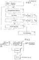
- Fig. 1 ein Flußdiagramm als Ausführungsbeispiel für den Ablauf des erfindungsgemäßen Verfahrens und
- Fig. 2 ein weiteres Ausführungsbeispiel in einem BJockschaltbild.
- Fig. 1 is a flow chart as an embodiment for the execution of the method according to the invention and
- Fig. 2 shows another embodiment in a block diagram.
In dem Flußdiagramm der Fig. 1 bedeuten:
- U die Unwuchtgröße des auszuwuchtenden Rotors;
- US max den Maximalwert des Unwuchtmeßsignals;
- US min den Minimalwert des Unwuchtmeßsignals.
- U the unbalance size of the rotor to be balanced;
- US max the maximum value of the unbalance measurement signal;
- US min the minimum value of the unbalance measurement signal.
Der Ablauf ist folgender:
- 1. Zu Beginn der Meßaufnahmne werden die Speicherstellen US max und US min durch Überschreiten mit Maximal- und Minimalwerten gelöscht.
- 2. Die momentane Unwuchtgröße U wird gemessen.
- 3. Die gemessene Unwuchtgröße wird mit dem abgelegten Maximalwert US max verglichen.
- 4. Ist die gemessene Unwuchtgröße größer als der bisherige Maximalwert US max, wird US max mit der gemessenen Unwuchtgröße überschrieben.
- 5. Wenn die gemessene Unwuchtgröße U kleiner als US max ist, wird sie mit dem Minimalwert US min verglichen.
- 6. Ist die gemessene Unwuchtgröße kleiner als der bisherige Minimalwert US min, wird US min mit der gemessenen Unwuchtgröße überschrieben.
- 7. Wenn die Meßzeit für die Maximal- und Minimalwerterfassung noch nicht abgelaufen ist, wiederholt sich der Vorgang der vorstehenden Schritte 2 bis 6.
- 8. Wenn die Meßzeit abgelaufen ist, wird die Toleranz T aus den nun vorhandenen Maximal- und Minimalwerten US max und US min nach der Formel

- 1. At the beginning of the measurement, the storage locations US max and US min are exceeded by exceeding the maximum and Minimum values deleted.
- 2. The current unbalance variable U is measured.
- 3. The measured unbalance size is compared with the stored maximum value US max.
- 4. If the measured unbalance size is greater than the previous maximum value US max, US max is overwritten with the measured unbalance size.
- 5. If the measured unbalance quantity U is smaller than US max, it is compared with the minimum value US min.
- 6. If the measured unbalance size is smaller than the previous minimum value US min, US min is overwritten with the measured unbalance size.
- 7. If the measurement time for the maximum and minimum value acquisition has not yet expired, the process of steps 2 to 6 is repeated.
- 8. When the measuring time has elapsed, the tolerance T becomes from the maximum and minimum values US max and US min now available according to the formula
Wenn das von den Meßwertgebern kommende Unwuchtmeßsignal durch phasenabhängige Gleichrichtung ausgewertet wird, wird der Störfaktor aus dem Vergleich der Werte des Unwuchtmeßsignals vor und nach der phasenabhängigen Gleichrichtung bestinmt. Bei der phasenabhängigen Gleichrichtung (DE-AS 11 08 475, Hofmann-Info Nr. 2 der Firma Gebr. Hofmann GmbH & Co. KG, D-6102 Pfungstadt, Hofmann News Nr. 5 der Firma Gebr. Hofmann GmbH & Co. KG, D-6102 Pfungstadt) wird die von den Meßwertaufnehmern kommende Unwuchtschwingung mit einer rotationsfrequenten rechteckförmigen Phasenbezugsspannung gleichgerichtet und anschließend über ein RC-Glied integriert. Hierbei werden zwei Gleichrichter eingesetzt, die in o ihrer Wirkung um 90 phasenverschoben sind. Es werden dabei zwei Gleichspannungen gebildet, die das Unwuchtsignal nach Größe und Phasenlage beinhalten. Bei der phasenabhängigen Gleichrichtung werden alle Störschwingungen und geradzahligen Oberwellen herausgefiltert. Die ungeradzahligen Oberwellen werden mittels eines zwischen den Meßwertaufnehmern und der Schaltung für die phasenabhängige Gleichrichtung eingefügten Filters, das relativ breitbandig ist, unterdrückt. Dieses Filter kann als sogenanntes Trackingfilter (Auto-Tracking-Meßverfahren in Hofmann News Nr. 5 der Firma Gebr. Hofmann GmbH & Co. KG, D-6102 Pfungstadt) ausgebildet sein und wird mit der Drehzahl des Wuchtkörpers über den ganzen Drehzahlbereich hin nachgestimmt. Auf diese Weise werden die im Meßsignal enthaltenen Störsignale unterdrückt.If the unbalance measurement signal coming from the sensors is evaluated by phase-dependent rectification, the interference factor is determined by comparing the values of the unbalance measurement signal before and after the phase-dependent rectification. For phase-dependent rectification (DE-AS 11 08 475, Hofmann Info No. 2 from Gebr. Hofmann GmbH & Co. KG, D-6102 Pfungstadt, Hofmann News No. 5 from Gebr. Hofmann GmbH & Co. KG, D-6102 Pfungstadt) the unbalance vibration coming from the transducers is rectified with a rotation-frequency rectangular phase reference voltage and then integrated via an RC element. Here two rectifiers are used, which are 90 phase-shifted in their effect. Two DC voltages are formed which contain the unbalance signal according to size and phase position. With phase-dependent rectification, all interference vibrations and even harmonics are filtered out. The odd harmonics are determined by means of a between the transducers and the Circuit for phase-dependent rectification inserted filter, which is relatively broadband, suppressed. This filter can be designed as a so-called tracking filter (auto-tracking measurement method in Hofmann News No. 5 from Gebr. Hofmann GmbH & Co. KG, D-6102 Pfungstadt) and is adjusted with the speed of the balancing body over the entire speed range. In this way, the interference signals contained in the measurement signal are suppressed.
Aus der Fig. 2 ist zu ersehen, daß das vom Meßwertgeber kommende, die Störsignale noch enthaltende Unwuchtrneßsignal einem Breitbandfilter 1 zugeführt wird. Der Ausgangs des Breitbandfilters 1 ist an den Eingang einer Schaltung 2 zur phasenabhängigen Gleichrichtung, wie sie beispielsweise aus der DE-AS 11 08 475 bekannt ist und an einen Vergleicher 3 angeschlossen. Der Ausgang der Schaltung 2 i.st mit einem weiteren Eingang des Vergleichers 3 verbunden. Das Ausgangssignal der Schaltung 2 wird außerdem weitergegeben an eine Speicher- und/oder Anzeigeeinrichtung für die Unwuchtgröße und Unwuchtwinkellage. Durch die kombinierte Anordnung des über den gesamten Drehzahlbereich des Wuchtkörpers kontinuierlich mitgeführten Breitbandfilters 1 und der phasenempfindlichen Gleichrichtung 2 werden neben der Auswertung der vom Meßgeber kommenden Unwuchtmeßsignale, wie schon erwähnt, auch die in diesen Signalen enthaltenen Störsignale unterdrückt. Die im Vergleicher 3 ermittelte Differenz zwischen den Eingangs- und Ausgangssignalen der Schaltung 2 für die phasenempfindliche Gleichrichtung stellt ein Maß für den Störanteil dar und wird als Störfaktor N mit dem in Abhängigkeit von zulässigen Schwankungen des Unwuchtmeßsignals bestimmten Multiplikator TM in einem an den Ausgang des Vergleichers 3 angeschlossenen Multiplizierer 4 zur Bestinmung der Toleranz T gemäß der nachstehenden Gleichung multipliziert:![]()
![]()
Bei dem im Zusammenhang mit der Fig. 1 beschriebenen Ausführungsbeispiel wird der Störanteil N (USmax-USmin) ermitn telt und mit dem vorher ermittelten Störanteil N vernl glichen. Wenn eine Differenz zwischen den beiden Störanteilen N und N vorhanden ist, erfolgt eine Multiplikation n n-1 des Störanteils N mit dem Multiplikator TM zur Neufestn legung der Toleranz T.In the exemplary embodiment described in connection with FIG. 1, the interference component N (USmax-USmin) is determined and compared with the previously determined interference component N. If there is a difference between the two interference components N and N, the interference component N is multiplied n n-1 by the multiplier TM to redefine the tolerance T.
Bei dein Ausführungsbeispiel, welches mit Hilfe der in der Fig. 2 dargestellten Anordnung durchgeführt wird, erfolgt die bestirrmung des Störanteils N durch den Vergleich der n Unwuchtmeßsignale, welche an einer Stelle zwischen dem Meßwertgeber und der phasengesteuerten Gleichrichterschaltung 2, insbesondere am Eingang der phasengesteuerten Gleichrichterschaltung 2 und dem Ausgang dieser Schaltung 2 vorhanden sind. Wenn zwischen den Störanteilen N und den vorher bestimmten n Störanteilen N eine Differenz vorhanden ist, erfolgt eine n-1 Multiplikation des Störanteils N mit dem Multiplikator TM n zur Neufestlegung der Toleranz.In your embodiment, which is carried out with the aid of the arrangement shown in FIG. 2, the interference component N is determined by comparing the n unbalance measurement signals which occur at a point between the transmitter and the phase-controlled rectifier circuit 2, in particular at the input of the phase-controlled rectifier circuit 2 and the output of this circuit 2 are present. If there is a difference between the interference components N and the previously determined n interference components N, the interference component N is multiplied n-1 by the multiplier TM n to redefine the tolerance.
Diese beiden Verfahren können gleichzeitig oder alternativ zum Einsatz kommen, so daß die Toleranz T jeweils durch das eine oder das andere Verfahren neu festgelegt wird. Theoretisch kann also die Toleranz durch die beiden Ausführungsbeispiele sehr klein gemacht werden und dies kann unter Umständen zu einem Überregelverhalten führen. Um dies zu vermeiden, kann in bevorzugter Weise gleichzeitig ein Verfahren zum Einsatz gebracht werden, durch welches die Toleranzänderung nach unten hin begrenzt wird. Dabei wird von der Überlegung ausgegangen, daß eine kleine Toleranz T automatisch zu einer größeren Schwankungsbreite der Phasenlage führt, so daß die kleinste Toleranz durch eine maximal zulässige Schwankungsbreite der Phasenlage sich festlegen läßt.These two methods can be used simultaneously or alternatively, so that the tolerance T is determined anew by one or the other method. Theoretically, the tolerance can thus be made very small by the two exemplary embodiments, and this can lead to over-regulation behavior under certain circumstances. In order to avoid this, a method can preferably be used at the same time by which the tolerance change is limited downwards. It is assumed that a small tolerance T automatically leads to a larger fluctuation range in the phase position, so that the smallest tolerance is due to a maximum permissible fluctuation range of the phase position can be determined.
Hierbei wird jeweils die Phase des Unwuchtsignals gemessen und die Schwankungsbreite der Phasenlage ermittelt. Sobald diese Schwankungsbreite einen bestimmten Wert, insbesondere 0,5 bis 10 , z.B. aufgrund größerer Störungen, überschreitet, wird aus dem dann vorhandenen Unwuchtmeßsignal der entsprechende Störanteil N ermittelt und zur Neufestlegung der Toleranz mit dem in Abhängigkeit von zulässigen Schwankungen des Unwuchtmeßsignals bestimmten Multiplikator TM gemäß der vorstehenden Gleichung multipliziert.The phase of the unbalance signal is measured and the fluctuation range of the phase position is determined. As soon as this fluctuation range reaches a certain value, in particular 0.5 to 10, e.g. due to larger disturbances, the corresponding disturbance component N is determined from the then existing unbalance measurement signal and multiplied to redefine the tolerance by the multiplier TM determined as a function of permissible fluctuations in the unbalance measurement signal in accordance with the above equation.
Die Durchführung des vorstehenden Verfahrens zur Errnittlung der geeigneten Toleranzgröße für zulässige Unwuchtmeßsignalschwankungen empfiehlt sich jeweils vor Beginn eines Ausgleichsvorgangs, damit ein Überregelverhalten während des Ausgleichsvorgangs vermieden wird. Wenn die Unwuchtrneßsignalschwankungen innerhalb des Toleranzbereiches liegen, werden keine Ausgleichsvorgänge mehr eingeleitet bzw. wird der jeweilige Ausgleichsvorgang beendet.It is advisable to carry out the above procedure for determining the suitable tolerance variable for permissible unbalance measurement signal fluctuations before the start of a compensation process, so that over-regulation behavior is avoided during the compensation process. If the unbalance signal fluctuations are within the tolerance range, no more compensation processes are initiated or the respective compensation process is ended.
Claims (8)
Priority Applications (1)
| Application Number | Priority Date | Filing Date | Title |
|---|---|---|---|
| AT85112577T ATE49054T1 (en) | 1985-03-26 | 1985-10-04 | METHOD OF CONTINUOUSLY COMPENSATING AN IMBALANCE OF A ROTOR, ESPECIALLY A GRINDING DISC, AND CIRCUIT ARRANGEMENT THEREOF. |
Applications Claiming Priority (2)
| Application Number | Priority Date | Filing Date | Title |
|---|---|---|---|
| DE3510950 | 1985-03-26 | ||
| DE19853510950 DE3510950A1 (en) | 1985-03-26 | 1985-03-26 | METHOD FOR CONTINUOUSLY BALANCING A BALANCE OF A ROTOR, ESPECIALLY A GRINDING DISC, AND CIRCUIT ARRANGEMENT THEREFOR |
Publications (3)
| Publication Number | Publication Date |
|---|---|
| EP0195845A2 true EP0195845A2 (en) | 1986-10-01 |
| EP0195845A3 EP0195845A3 (en) | 1988-05-18 |
| EP0195845B1 EP0195845B1 (en) | 1989-12-27 |
Family
ID=6266379
Family Applications (1)
| Application Number | Title | Priority Date | Filing Date |
|---|---|---|---|
| EP85112577A Expired EP0195845B1 (en) | 1985-03-26 | 1985-10-04 | Continuous rotor-balancing process, in particular for a grinding disc, and circuit arrangement therefor |
Country Status (5)
| Country | Link |
|---|---|
| US (1) | US4688355A (en) |
| EP (1) | EP0195845B1 (en) |
| JP (1) | JPH0658279B2 (en) |
| AT (1) | ATE49054T1 (en) |
| DE (1) | DE3510950A1 (en) |
Families Citing this family (8)
| Publication number | Priority date | Publication date | Assignee | Title |
|---|---|---|---|---|
| WO1988007186A1 (en) * | 1987-03-19 | 1988-09-22 | Leningradskoe Vysshee Inzhenernoe Morskoe Uchilisc | Device for automatic balancing of abrasive disks |
| SE461279B (en) * | 1988-05-30 | 1990-01-29 | Electrolux Ab | METHOD FOR BALANCING A CIRCUIT AND A SIGNIFICANT HORIZONTAL AXEL ROTARY BEHAVIOR |
| US5005439A (en) * | 1989-07-14 | 1991-04-09 | Barry Wright Corporation | Inertia force generating device |
| US5343408A (en) * | 1991-08-09 | 1994-08-30 | Industrial Technology Research Institute | Device for on-line automatic fluid injection balancing system |
| US5354186A (en) * | 1993-08-12 | 1994-10-11 | The Board Of Regents Of The University Of Michigan | Machine balancer with peristaltic fluid pump |
| DE19729172C1 (en) * | 1997-07-08 | 1998-07-30 | Hofmann Mes Und Auswuchttechni | Continuous balancing method for grinding wheel or rotor |
| US7267029B2 (en) * | 2001-11-14 | 2007-09-11 | Lord Corporation | Balancing device for a rotating member and associated methods |
| JP6174545B2 (en) * | 2014-10-17 | 2017-08-02 | ファナック株式会社 | Cutting fluid condition monitoring device using odor sensor |
Citations (2)
| Publication number | Priority date | Publication date | Assignee | Title |
|---|---|---|---|---|
| US3646601A (en) * | 1969-10-22 | 1972-02-29 | Gen Motors Corp | Off-angle balance correction method and apparatus |
| EP0052015A2 (en) * | 1980-11-11 | 1982-05-19 | Matsushita Electric Industrial Co., Ltd. | Method of correcting unbalance of a rotating body |
Family Cites Families (3)
| Publication number | Priority date | Publication date | Assignee | Title |
|---|---|---|---|---|
| DE2357629A1 (en) * | 1973-11-19 | 1975-05-28 | Hofmann Maschf Geb | DEVICE FOR COMPENSATING THE BALANCE OF A ROTATING BODY, IN PARTICULAR A GRINDING DISC |
| US4432253A (en) * | 1981-04-20 | 1984-02-21 | Balance Dynamics Co. | Unbalance compensator |
| GB2097101B (en) * | 1981-04-20 | 1984-11-14 | Kerlin Jack Harnsworth | Unbalance compensator and method of distributing balancing mass in same |
-
1985
- 1985-03-26 DE DE19853510950 patent/DE3510950A1/en active Granted
- 1985-10-04 AT AT85112577T patent/ATE49054T1/en not_active IP Right Cessation
- 1985-10-04 EP EP85112577A patent/EP0195845B1/en not_active Expired
-
1986
- 1986-03-20 JP JP61063860A patent/JPH0658279B2/en not_active Expired - Lifetime
- 1986-03-25 US US06/843,608 patent/US4688355A/en not_active Expired - Lifetime
Patent Citations (2)
| Publication number | Priority date | Publication date | Assignee | Title |
|---|---|---|---|---|
| US3646601A (en) * | 1969-10-22 | 1972-02-29 | Gen Motors Corp | Off-angle balance correction method and apparatus |
| EP0052015A2 (en) * | 1980-11-11 | 1982-05-19 | Matsushita Electric Industrial Co., Ltd. | Method of correcting unbalance of a rotating body |
Also Published As
| Publication number | Publication date |
|---|---|
| US4688355A (en) | 1987-08-25 |
| ATE49054T1 (en) | 1990-01-15 |
| EP0195845A3 (en) | 1988-05-18 |
| EP0195845B1 (en) | 1989-12-27 |
| JPH0658279B2 (en) | 1994-08-03 |
| DE3510950C2 (en) | 1988-09-29 |
| JPS61223627A (en) | 1986-10-04 |
| DE3510950A1 (en) | 1986-10-02 |
Similar Documents
| Publication | Publication Date | Title |
|---|---|---|
| EP0335080B1 (en) | Method and apparatus for determining the size of cross-wound packages and for utilising the results | |
| EP0195845B1 (en) | Continuous rotor-balancing process, in particular for a grinding disc, and circuit arrangement therefor | |
| DE1947090B2 (en) | Device for determining the unbalance of wheels | |
| EP0190397B1 (en) | Method for the continuous compensation of an unbalanced state of a rotor, especially of a grinding wheel | |
| DE19527062A1 (en) | Method and device for the calibration of torque measuring devices | |
| DE4304956C2 (en) | Method and device for warping threads | |
| DE2506068A1 (en) | NON-TOUCH SELF-ALIGNING VIBRATION SENSOR | |
| DE2518503C2 (en) | ||
| DE4117637A1 (en) | CONTROL DEVICE FOR A CUTTING MACHINE TOOL | |
| EP0407628A1 (en) | Process and device for eliminating the influence of periodic disturbance values with a known varying frequency | |
| EP0417414B1 (en) | Method and devices for compensating the imbalance of a grindstone | |
| DE3040713C2 (en) | Device for setting a force-measuring balancing machine | |
| DE4235614A1 (en) | Procedure for determining the unbalance of a loaded washing machine drum | |
| EP0099937B1 (en) | Device for determining position and size of unbalance | |
| EP0347883B1 (en) | Process and device for balancing rotating parts | |
| DE19903922A1 (en) | Wheel speed detection unit for measuring speeds | |
| DE3642130C2 (en) | ||
| DE102013110632A1 (en) | Method for measuring the expansion of a rotating rotor | |
| DE4015051A1 (en) | DEVICE AND METHOD FOR BALANCING A ROTOR | |
| DE2908272C2 (en) | Device for balancing rotors | |
| DE19743577A1 (en) | Method to prepare balancing machine for balancing operation | |
| DE3017240C2 (en) | Device for determining the imbalance of wheels mounted on motor vehicles | |
| WO2006042845A1 (en) | Control and/or regulating device for a motor | |
| DE19729172C1 (en) | Continuous balancing method for grinding wheel or rotor | |
| DE3812371A1 (en) | Method for measuring the distribution of washing, especially in washing machines |
Legal Events
| Date | Code | Title | Description |
|---|---|---|---|
| PUAI | Public reference made under article 153(3) epc to a published international application that has entered the european phase |
Free format text: ORIGINAL CODE: 0009012 |
|
| AK | Designated contracting states |
Kind code of ref document: A2 Designated state(s): AT BE CH FR GB IT LI NL |
|
| PUAL | Search report despatched |
Free format text: ORIGINAL CODE: 0009013 |
|
| AK | Designated contracting states |
Kind code of ref document: A3 Designated state(s): AT BE CH FR GB IT LI NL |
|
| 17P | Request for examination filed |
Effective date: 19880615 |
|
| 17Q | First examination report despatched |
Effective date: 19890210 |
|
| ITF | It: translation for a ep patent filed |
Owner name: DR. ING. A. RACHELI & C. |
|
| GRAA | (expected) grant |
Free format text: ORIGINAL CODE: 0009210 |
|
| AK | Designated contracting states |
Kind code of ref document: B1 Designated state(s): AT BE CH FR GB IT LI NL |
|
| REF | Corresponds to: |
Ref document number: 49054 Country of ref document: AT Date of ref document: 19900115 Kind code of ref document: T |
|
| ET | Fr: translation filed | ||
| GBT | Gb: translation of ep patent filed (gb section 77(6)(a)/1977) | ||
| PLBE | No opposition filed within time limit |
Free format text: ORIGINAL CODE: 0009261 |
|
| STAA | Information on the status of an ep patent application or granted ep patent |
Free format text: STATUS: NO OPPOSITION FILED WITHIN TIME LIMIT |
|
| 26N | No opposition filed | ||
| ITTA | It: last paid annual fee | ||
| REG | Reference to a national code |
Ref country code: CH Ref legal event code: PUE Owner name: HOFMANN WERKSTATT-TECHNIK GMBH TRANSFER- HOFMANN M |
|
| NLS | Nl: assignments of ep-patents |
Owner name: HOFMANN WERKSTATT-TECHNIK GMBH |
|
| NLS | Nl: assignments of ep-patents |
Owner name: HOFFMANN MASCHINENBAU GMBH |
|
| REG | Reference to a national code |
Ref country code: GB Ref legal event code: 732E |
|
| PGFP | Annual fee paid to national office [announced via postgrant information from national office to epo] |
Ref country code: FR Payment date: 19971027 Year of fee payment: 13 |
|
| PGFP | Annual fee paid to national office [announced via postgrant information from national office to epo] |
Ref country code: NL Payment date: 19971031 Year of fee payment: 13 Ref country code: AT Payment date: 19971031 Year of fee payment: 13 |
|
| PGFP | Annual fee paid to national office [announced via postgrant information from national office to epo] |
Ref country code: BE Payment date: 19971114 Year of fee payment: 13 |
|
| PG25 | Lapsed in a contracting state [announced via postgrant information from national office to epo] |
Ref country code: AT Free format text: LAPSE BECAUSE OF NON-PAYMENT OF DUE FEES Effective date: 19981004 |
|
| PGFP | Annual fee paid to national office [announced via postgrant information from national office to epo] |
Ref country code: GB Payment date: 19981006 Year of fee payment: 14 |
|
| REG | Reference to a national code |
Ref country code: CH Ref legal event code: PUE Owner name: HOFMANN MASCHINENBAU GMBH TRANSFER- SCHMITT-HOFMAN |
|
| PG25 | Lapsed in a contracting state [announced via postgrant information from national office to epo] |
Ref country code: BE Free format text: LAPSE BECAUSE OF NON-PAYMENT OF DUE FEES Effective date: 19981031 |
|
| REG | Reference to a national code |
Ref country code: GB Ref legal event code: 732E |
|
| PGFP | Annual fee paid to national office [announced via postgrant information from national office to epo] |
Ref country code: CH Payment date: 19981106 Year of fee payment: 14 |
|
| BERE | Be: lapsed |
Owner name: HOFMANN MASCHINENBAU G.M.B.H. Effective date: 19981031 |
|
| PG25 | Lapsed in a contracting state [announced via postgrant information from national office to epo] |
Ref country code: NL Free format text: LAPSE BECAUSE OF NON-PAYMENT OF DUE FEES Effective date: 19990501 |
|
| PG25 | Lapsed in a contracting state [announced via postgrant information from national office to epo] |
Ref country code: FR Free format text: LAPSE BECAUSE OF NON-PAYMENT OF DUE FEES Effective date: 19990630 |
|
| NLV4 | Nl: lapsed or anulled due to non-payment of the annual fee |
Effective date: 19990501 |
|
| REG | Reference to a national code |
Ref country code: FR Ref legal event code: ST |
|
| PG25 | Lapsed in a contracting state [announced via postgrant information from national office to epo] |
Ref country code: GB Free format text: LAPSE BECAUSE OF NON-PAYMENT OF DUE FEES Effective date: 19991004 |
|
| PG25 | Lapsed in a contracting state [announced via postgrant information from national office to epo] |
Ref country code: LI Free format text: LAPSE BECAUSE OF NON-PAYMENT OF DUE FEES Effective date: 19991031 Ref country code: CH Free format text: LAPSE BECAUSE OF NON-PAYMENT OF DUE FEES Effective date: 19991031 |
|
| GBPC | Gb: european patent ceased through non-payment of renewal fee |
Effective date: 19991004 |
|
| REG | Reference to a national code |
Ref country code: CH Ref legal event code: PL |