EP0190397B1 - Method for the continuous compensation of an unbalanced state of a rotor, especially of a grinding wheel - Google Patents
Method for the continuous compensation of an unbalanced state of a rotor, especially of a grinding wheel Download PDFInfo
- Publication number
- EP0190397B1 EP0190397B1 EP85112576A EP85112576A EP0190397B1 EP 0190397 B1 EP0190397 B1 EP 0190397B1 EP 85112576 A EP85112576 A EP 85112576A EP 85112576 A EP85112576 A EP 85112576A EP 0190397 B1 EP0190397 B1 EP 0190397B1
- Authority
- EP
- European Patent Office
- Prior art keywords
- compensating
- unbalance
- rotor
- amount
- fluid
- Prior art date
- Legal status (The legal status is an assumption and is not a legal conclusion. Google has not performed a legal analysis and makes no representation as to the accuracy of the status listed.)
- Expired
Links
- 238000000034 method Methods 0.000 title claims abstract description 23
- 230000005540 biological transmission Effects 0.000 claims abstract description 14
- 239000012530 fluid Substances 0.000 claims abstract 8
- 238000012360 testing method Methods 0.000 claims description 10
- 238000006073 displacement reaction Methods 0.000 claims 4
- 230000010363 phase shift Effects 0.000 abstract description 13
- 239000007788 liquid Substances 0.000 description 12
- 238000003754 machining Methods 0.000 description 6
- 238000011156 evaluation Methods 0.000 description 4
- 239000000463 material Substances 0.000 description 4
- 238000005259 measurement Methods 0.000 description 4
- 238000012545 processing Methods 0.000 description 4
- 238000001514 detection method Methods 0.000 description 2
- 230000010355 oscillation Effects 0.000 description 2
- 230000001133 acceleration Effects 0.000 description 1
- 238000013016 damping Methods 0.000 description 1
- 230000001419 dependent effect Effects 0.000 description 1
- 238000011161 development Methods 0.000 description 1
- 230000018109 developmental process Effects 0.000 description 1
- 238000010586 diagram Methods 0.000 description 1
- 230000000694 effects Effects 0.000 description 1
- 230000005284 excitation Effects 0.000 description 1
- 230000005484 gravity Effects 0.000 description 1
- 238000000691 measurement method Methods 0.000 description 1
- 230000002093 peripheral effect Effects 0.000 description 1
- 238000012546 transfer Methods 0.000 description 1
- 230000007704 transition Effects 0.000 description 1
- 230000001960 triggered effect Effects 0.000 description 1
Images
Classifications
-
- G—PHYSICS
- G01—MEASURING; TESTING
- G01M—TESTING STATIC OR DYNAMIC BALANCE OF MACHINES OR STRUCTURES; TESTING OF STRUCTURES OR APPARATUS, NOT OTHERWISE PROVIDED FOR
- G01M1/00—Testing static or dynamic balance of machines or structures
- G01M1/30—Compensating imbalance
- G01M1/32—Compensating imbalance by adding material to the body to be tested, e.g. by correcting-weights
- G01M1/323—Compensating imbalance by adding material to the body to be tested, e.g. by correcting-weights using balancing liquid
Definitions
- the invention relates to a method according to the preamble of claim 1.
- the rotor works in the subcritical and supercritical range and passes through the critical speed range during the transition from the subcritical to the supercritical range.
- the critical speed range there is a phase shift between the unbalance angle position and the associated oscillating movement from 0 ° to 180 °.
- the oscillation signal determined by the measuring sensor can then no longer be used for the targeted control of the mass balance, since the phase shift course mentioned naturally arises when the critical speed range is passed through.
- the imbalance signal emitted by the encoder is also influenced by the machine behavior, which is not known and is constantly changing, because in material processing with the help of rotors, e.g. B. with the help of grinding wheels, the mass of the rotor changes continuously.
- constant balancing of the rotor, in particular the grinding wheel is required during the machining operation in order to avoid poor machining quality, rattling, ripples and undesired relative movements between the workpiece and the turning tool.
- the object of the invention is therefore to provide a method of the type mentioned in the introduction, in which precise balancing of the rotor is achieved during operation, even when the rotor passes through the critical speed range.
- the test quantity of the compensation liquid For the measurement of the test quantity of the compensation liquid to be introduced into one of the compensation chambers during a compensation process, it is advisable to select the smallest, exactly reproducible quantity of compensation liquid. This is predetermined by the switching times of the valves with which the introduction of the compensating liquid into the compensating chambers is measured, the working speed of the evaluation electronics or the computer used for the evaluation and the pressure that is normally present in the supply line for the compensating liquid.
- the test quantity of the compensating liquid is preferably introduced into the chamber opposite the determined unbalance angle position, because in this way the best possible accuracy in determining the transfer function that becomes effective between the rotor and the sensor, which is known as the phase shift described above and as an amplitude error in the sensor for the Unbalance variable output amplitude signal compared to the actual unbalance variable present on the rotor.
- the phase shift determined in the respective compensation process is preferably stored as an initial value for the next subsequent compensation process. This results in a fine-tuned phase adjustment for the successive compensation processes, especially in the critical speed range, or a self-learning process is achieved when the phase shift or the scaling factor is stored for a subsequent subsequent determination of the transmission behavior (phase shift, amplitude transmission error) of the transmission path between the rotor and the encoder is saved.
- the balancing liquid required is preferably distributed to two balancing chambers.
- 1a shows the amplitude profile of a damped oscillating, unbalanced rotor, the ratio ⁇ of the excitation angular frequency n of the unbalanced rotor to the natural angular frequency ⁇ e of the rotor on the abscissa and the ratio of the oscillation path vector X to the center of gravity s on the ordinate are applied.
- a grinding wheel 1 is shown by a sleep machine (not shown in detail), the imbalances which arise during the grinding operation are continuously compensated in successive compensating processes.
- the vibrations caused by the unbalance of the grinding wheel 1 are detected via a transmission link 5 by a measuring transducer 2, in particular an acceleration sensor, and are forwarded to measuring and control electronics 3 in the form of corresponding measuring signals.
- This electronics is composed of measuring electronics 3a, in which the unbalance of the grinding wheel 1 is continuously determined over the entire speed range of the grinding wheel according to size and direction, and a downstream evaluation and control electronics 3b, in which, depending on the respectively determined unbalance values
- a valve device 4 of a compensation device known from DE-OS 23 57 629 for example, but not shown in the figure, is actuated.
- phase difference (phase shift ⁇ p) between the unbalance angle position and the oscillating movement triggered by this, as well as the machine-related amplitude transmission error in the transmission path 5, are detected by the measuring electronics 3 a in the detection of the measuring signals emitted by the measuring transmitter 2
- Evaluation electronics 3b which can be, for example, a computer, are determined as follows and then used to control the valves of the valve device 4 accordingly.
- the values of the initial unbalance which are still affected by the phase error and amplitude error, are used to determine the balance of the test liquid and the angular position of the chamber into which the test liquid was introduced, as well as the measured residual unbalance the introduction of the test quantity of the compensating liquid, the amplitude errors and the phase errors in the transmission path 5 are determined and used in the dimensioning of the compensating quantity with which the residual unbalance is compensated.
- the scaling factor for the phase shift is saved and can be used to determine the phase delay in the subsequent unbalance compensation process.
- the corresponding valve or the corresponding valves of the valve device 4 is then opened for a certain period of time, so that the corresponding equalizing amount of the equalizing liquid is introduced into the corresponding equalizing chamber or corresponding equalizing chamber.
Landscapes
- Physics & Mathematics (AREA)
- General Physics & Mathematics (AREA)
- Testing Of Balance (AREA)
- Constituent Portions Of Griding Lathes, Driving, Sensing And Control (AREA)
- Grinding Of Cylindrical And Plane Surfaces (AREA)
Abstract
Description
Die Erfindung betrifft ein Verfahren nach dem Oberbegriff des Anspruchs 1.The invention relates to a method according to the preamble of
Ein derartiges Verfahren ist aus der DE-OS 2357629 bekannt. Bei der Anwendung von Schleifscheiben oder ähnlichen Rotoren zur Bearbeitung von Werkstücken wird im Gegensatz zum bekannten Verfahren, bei dem eine konstante Drehzahl der Schleifscheibe vorliegt, eine konstante Schnittgeschwindigkeit und damit eine konstante Geschwindigkeit der zur Materialbearbeitung dienenden Umfangsfläche des Rotors gefordert. Bei der Materialbearbeitung ergibt sich zwangsläufig eine Abnutzung an der Arbeitsfläche am Umfpang des Rotors, insbesondere der Schleifscheibe, weshalb dann die Drehzahl des Rotors erhöht werden muß. In der Praxis ist es so, daß das Durchfahren eines Drehzahlbereichs von 750 bis 2 000 Umdrehungen pro Minute erforderlich wird. Es läßt sich dann nicht mehr vermeiden, daß aufgrund der zwangsläufig vorgegebenen Massen von Lager, Spindel und Rotor, z. B. Spindelstock und Schleifscheibe, der Rotor im unterkritischen und überkritischen Bereich arbeitet und beim Übergang vom unterkritischen in den überkritischen Bereich den kritischen Drehzahlbereich durchläuft. Beim Durchlaufen des kritischen Drehzahlbereichs erfolgt eine Phasenverschiebung zwischen der Unwuchtwinkellage und der zugehörigen Schwingbewegung von 0° nach 180°. Das vom Meßgeber ermittelte Schwingungssignal kann dann nicht mehr zur gezielten Steuerung des Massenausgleichs verwendet werden, da beim Durchlaufen des kritischen Drehzahlbereichs die angesprochene Phasenverschiebungsverlauf sich naturgemäß einstellt.Such a method is known from DE-OS 2357629. When using grinding wheels or similar rotors for machining workpieces, in contrast to the known method, in which there is a constant rotational speed of the grinding wheel, a constant cutting speed and thus a constant speed of the peripheral surface of the rotor used for material processing is required. During material processing there is inevitable wear on the working surface on the circumference of the rotor, in particular the grinding wheel, which is why the speed of the rotor must then be increased. In practice it is necessary to drive through a speed range of 750 to 2,000 revolutions per minute. It can then no longer be avoided that due to the inevitably predetermined masses of bearings, spindle and rotor, for. B. headstock and grinding wheel, the rotor works in the subcritical and supercritical range and passes through the critical speed range during the transition from the subcritical to the supercritical range. When passing through the critical speed range, there is a phase shift between the unbalance angle position and the associated oscillating movement from 0 ° to 180 °. The oscillation signal determined by the measuring sensor can then no longer be used for the targeted control of the mass balance, since the phase shift course mentioned naturally arises when the critical speed range is passed through.
Das vom Meßgeber abgegebene Unwuchtsignal wird auch noch vom Maschinenverhalten beeinflußt, das nicht bekannt ist und sich ständig ändert, weil bei der Materialbearbeitung mit Hilfe von Rotoren, z. B. mit Hilfe von Schleifscheiben, sich die Masse des Rotors laufend ändert. Andererseits ist jedoch, um eine genaue Materialbearbeitung zu erzielen, ein ständiges Auswuchten des Rotors, insbesondere der Schleifscheibe während des Bearbeitungsbetriebs, erforderlich, um schlechte Bearbeitungsqualität, Rattern, Welligkeiten und unerwünschte Relativbewegungen zwischen Werkstück und Drehwerkzeug zu vermeiden.The imbalance signal emitted by the encoder is also influenced by the machine behavior, which is not known and is constantly changing, because in material processing with the help of rotors, e.g. B. with the help of grinding wheels, the mass of the rotor changes continuously. On the other hand, in order to achieve precise material processing, constant balancing of the rotor, in particular the grinding wheel, is required during the machining operation in order to avoid poor machining quality, rattling, ripples and undesired relative movements between the workpiece and the turning tool.
Aufgabe der Erfindung ist es daher, ein Verfahren der eingangs genannten Art zu schaffen, bei dem auch beim Durchlaufen des Rotors durch den kritischen Drehzahlbereich eine genaue Auswuchtung des Rotors während des Betriebs erreicht wird.The object of the invention is therefore to provide a method of the type mentioned in the introduction, in which precise balancing of the rotor is achieved during operation, even when the rotor passes through the critical speed range.
Diese Aufgabe wird erfindungsgemäß durch die kennzeichnenden Merkmale des Anspruchs 1 gelöst.This object is achieved by the characterizing features of
Die abhängigen Ansprüche kennzeichnen vorteilhafte Weiterbildungen der Erfindung.The dependent claims characterize advantageous developments of the invention.
Hierdurch wird in vorteilhafter Weise erreicht, daß die Bearbeitung eines Werkstücks mittels des Rotors immer mit konstanter Bearbeitungs- bzw. Schnittgeschwindigkeit erfolgen kann, wobei die Qualität der Bearbeitung aufgrund der genauen Auswuchtung des Rotors auch im kritischen Drehzahlbereich immer gewährleistet wird.In this way, it is advantageously achieved that the machining of a workpiece by means of the rotor can always take place at a constant machining or cutting speed, the quality of the machining being always guaranteed even in the critical speed range due to the precise balancing of the rotor.
Für die Bemessung der Testmenge der bei einem Ausgleichsvorgang zunächst in eine der Ausgleichskammern einzubringenden Ausgleichsflüssigkeit empfiehlt es sich, die kleinste genau reproduzierbare Menge an Ausgleichsflüssigkeit zu wählen. Diese ist vorgegeben durch die Schaltzeiten der Ventile, mit denen das Einbringen der Ausgleichsflüssigkeit in die Ausgleichskammern bemessen wird, der Arbeitsgeschwindigkeit der Auswerteelektronik bzw. des für die Auswertung verwendeten Rechners und dem normalerweise vorhandenen Druck in der Zuleitung für die Ausgleichsflüssigkeit.For the measurement of the test quantity of the compensation liquid to be introduced into one of the compensation chambers during a compensation process, it is advisable to select the smallest, exactly reproducible quantity of compensation liquid. This is predetermined by the switching times of the valves with which the introduction of the compensating liquid into the compensating chambers is measured, the working speed of the evaluation electronics or the computer used for the evaluation and the pressure that is normally present in the supply line for the compensating liquid.
Die Testmenge der Ausgleichsflüssigkeit wird bevorzugt in die der ermittelten Unwuchtwinkellage entgegengesetzt liegende Kammer eingebracht, weil hierdurch die bestmögliche Genauigkeit bei der Ermittlung der zwischen dem Rotor und dem Meßwertaufnehmer wirksam werdenden Übertragungsfunktion, die sich als die vorstehend bezeichnete Phasenverschiebung und als Amplitudenfehler im vom Meßgeber für die Unwuchtgröße abgegebenen Amplitudensignal gegenüber der tatsächlichen am Rotor vorhandenen Unwuchtgröße auswirkt.The test quantity of the compensating liquid is preferably introduced into the chamber opposite the determined unbalance angle position, because in this way the best possible accuracy in determining the transfer function that becomes effective between the rotor and the sensor, which is known as the phase shift described above and as an amplitude error in the sensor for the Unbalance variable output amplitude signal compared to the actual unbalance variable present on the rotor.
In bevorzugter Weise wird die bei dem jeweiligen Ausgleichsvorgang ermittelte Phasenverschiebung abgespeichert als Ausgangswert für den nächstfolgenden Ausgleichsvorgang. Man gewinnt dadurch für die aufeinanderfolgenden Ausgleichsvorgänge eine feingestufte Phasenanpassung, insbesondere im kritischen Drehzahlbereich, oder es wird ein Selbstlernprozeß erreicht, wenn die Abspeicherung der Phasenverschiebung bzw. des Skalierungsfaktors für eine erneute nachfolgende Ermittlung des Übertragungsverhaltens (Phasenverschiebung, Amplitudenübertragungsfehler) der Übertragungsstrecke zwischen Rotor und Meßgeber gespeichert wird.The phase shift determined in the respective compensation process is preferably stored as an initial value for the next subsequent compensation process. This results in a fine-tuned phase adjustment for the successive compensation processes, especially in the critical speed range, or a self-learning process is achieved when the phase shift or the scaling factor is stored for a subsequent subsequent determination of the transmission behavior (phase shift, amplitude transmission error) of the transmission path between the rotor and the encoder is saved.
Um Auswirkungen von Nichtlinearitäten bei der Übertragung der Unwuchtsignale gering zu halten, ist es von Vorteil, nur die Hälfte der für den Ausgleich der Restunwucht ermittelten Ausgleichsmenge der Ausgleichsflüssigkeit zu verwenden. Die benötigte Ausgleichsflüssigkeit wird bevorzugt auf zwei Ausgleichskammern verteilt.In order to keep the effects of non-linearities in the transmission of the unbalance signals low, it is advantageous to use only half of the compensation amount of the compensation liquid determined for the compensation of the residual unbalance. The balancing liquid required is preferably distributed to two balancing chambers.
Für die fortlaufende Unwuchtmessung empfiehlt sich das « Auto-Tracking-MeBverfahren », das aus Hofmann News, Nr. 5 der Fa. Gebr. Hofmann GmbH & Co., KG, D-6102 Pfungstadt bekannt ist. Bei diesem Verfahren handelt es sich um die Kombination eines über den gesamten Drehzahlbereich des Wuchtkörperps kontinuierlich mitgeführten Filters (Tracking-Filter), einer phasenempfindlichen Gleichrichtung und einer automatischen Selektivitätsanpassung während der Messung.For the continuous unbalance measurement, we recommend the "Auto-Tracking measurement method", which is known from Hofmann News, No. 5 from Gebr. Hofmann GmbH & Co., KG, D-6102 Pfungstadt. This method is a combination of a filter (tracking filter) carried along continuously over the entire speed range of the balancing body ps, a phase-sensitive rectification and an automatic selectivity adjustment during the measurement.
Die beiliegenden Figuren dienen zur weiteren Erläuterung der Erfindung. Es zeigt :
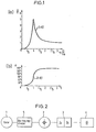
- Fig. 1 zwei Kurvendarstellungen für das schwingungsverhalten eines unwuchtigen Rotors, der aus dem unterkritischen Drehzahlbereich in den überkritischen Drehzahlbereich hochdreht ;
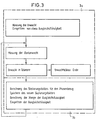
- Fig. 2 in schematischer Blockschaltbilddarstellung die Anordnung der einzelnen Funktionsbausteine, die bei Durchführung der Erfindung zur Anwendung kommen und
- Fig. 3 ein Flußdiagramm, in welchem der erfindungsgemäße Ablauf eines Auswuchtvorgangs dargestellt ist.
- 1 shows two graphs for the vibration behavior of an unbalanced rotor that revs up from the subcritical speed range to the supercritical speed range;
- Fig. 2 in a schematic block diagram representation of the arrangement of the individual function blocks that are used in carrying out the invention and
- Fig. 3 is a flow chart in which the sequence of a balancing process according to the invention is shown.
In der Kurvendarstellung der Fig. 1a ist der Amplitudenverlauf eines gedämpft schwingenden, unwuchtigen Rotors dargestellt, wobei auf der Abszisse das Verhältnis η von Erregerkreisfrequenz n des unwuchtigen Rotors zu der Eigenkreisfrequenz ωe des Rotors und auf der Ordinate des Verhältnis von Schwingwegvektor X zu Schwerpunktsexzentrizität s aufgetragen sind. Die Dämpfung D beträgt 0,1. In der Kurvendarstellung der Fig. 1 ist der Verlauf der Phasenverschiebung <p gegenüber dem vorstehend beschriebenen Frequenzverhältnis η aufgetragen und zwar beginnend im unterkritischen Drehzahlbereich (Phasenverschiebung <p = 0) ansteigend durch den kritischen Drehzahlbereich (Resonanzbereich) bis in den überkritischen Drehzahlbereich (Phasenverschiebung <p = 180°). Wie insbesondere aus der Kunrendarstellung 1b zu ersehen ist, verändert sich die Phasenverschiebung zwischen der Winkellage der Unwucht am Rotor gegenüber der hieraus resultierenden Schwingbewegung mit steigender Drehzahl sehr stark, so daß bei Rotoren, die in diesem Drehzahlbereich drehen bzw. arbeiten und eine Unwucht aufweisen, ein einwandfreier Unwuchtausgleich nicht möglich war.1a shows the amplitude profile of a damped oscillating, unbalanced rotor, the ratio η of the excitation angular frequency n of the unbalanced rotor to the natural angular frequency ω e of the rotor on the abscissa and the ratio of the oscillation path vector X to the center of gravity s on the ordinate are applied. The damping D is 0.1. 1 shows the course of the phase shift <p compared to the frequency ratio η described above, starting in the subcritical speed range (phase shift <p = 0 ) increasing through the critical speed range (resonance range) to the supercritical speed range (phase shift < p = 180 °). As can be seen in particular from the illustration of the customer 1b, the phase shift between the angular position of the imbalance on the rotor and the resulting oscillating movement changes very strongly with increasing speed, so that in rotors that rotate or work in this speed range and have an imbalance, perfect unbalance compensation was not possible.
Bei dem in der Fig. 2 dargestellten Ausführungsbeispiel einer Vorrichtung zur Durchführung der Erfindung ist von einer nicht näher dargestellten Schliefmaschine eine Schleifscheibe 1 gezeigt, deren während des Schleifbetriebs entstehende Unwuchten fortlaufend in aufeinandertolgenden Ausgleichsvorgängen ausgeglichen werden. Die von der Unwucht der Schleifscheibe 1 hervorgerufenen Schwingungen werden über eine Übertragungsstrecke 5 von einem Meßgeber 2, insbesondere einem Beschleunigungsaufnehmer erfaßt und in Form von entsprechenden Meßsignalen an eine Meß- und Regelelektronik 3 weitergeleitet. Diese Elektronik setzt sich zusammen aus einer Meßelektronik 3a, in welcher die Unwuchten der Schleifscheibe 1 über den gesamten Drehzahlbereich der Scheifscheibe hin fortlaufend nach Größe und Richtung ermittelt werden, und einer nachgeschalteten Auswerte- und Regelelektronik 3b, in der in Abhängigkeit von den jeweils ermittelten Unwuchtwerten, wie im einzelnen noch anhand der Fig. 3 erläutert wird, eine Ventileinrichtung 4 einer beispielsweise aus der DE-OS 23 57 629 bekannten in der Figur jedoch nicht näher dargestellten Ausgleichseinrichtung angesteuert wird.In the exemplary embodiment of a device for carrying out the invention shown in FIG. 2, a
Der bei der Erfassung der von der Rotorunwucht ausgelösten Schwingungen in der Übertragungsstrecke 5 vorhandene Phasenunterschied (Phasenverschiebung <p) zwischen Unwuchtwinkellage und hiervon ausgelöster Schwingbewegung sowie der maschinenbedingte Amplitudenübertragungsfehler in der Übertragungsstrecke 5 werden nach Erfassung der vom Meßgeber 2 abgegebenen Meßsignale durch die Meßelektronik 3a in der Auswerteelektronik 3b, welche beispielsweise ein Rechner sein kann, wie folgt festgestellt und dann zur entsprechenden Steuerung der Ventile der Ventileinrichtung 4 verwendet.The phase difference (phase shift <p) between the unbalance angle position and the oscillating movement triggered by this, as well as the machine-related amplitude transmission error in the
Nach dem Erfassen der vom Meßgeber 2 abgegebenen Unwuchtmeßsignale, welche noch mit dem auch maschinenbedingten Phasenfehler und Amplitudenfehler der Übertragungsstrecke 5 behaftet sind, wird eine geringe Testmenge der Ausgleichsflüssigkeit in die der Unwuchtwinkellage am Rotor 1 gegenüberliegende Ausgleichskammer eingespritzt. Es wird die hieraus resultierende Restunwucht wiederum gemessen und gegebenenfalls bei Einhaltung der Toleranz der Unwuchtausgleichsvorgang abgebrochen. Wenn die Restunwucht die Toleranzgrenze überschreitet, wird aus den Werten der Anfangsunwucht, die noch mit dem Phasenfehler und Amplitudenfehler behaftet sind, aus der Testmenge der Ausgleichsflüssigkeit und der Winkellage der Kammer, in welche die Testmenge der Ausgleichsflüssigkeit eingebracht wurde, sowie aus der gemessenen Restunwucht nach dem Einbringen der Testmenge der Ausgleichsflüssigkeit, der Amplitudenfehler und der Phasenfehler in der Übertragungsstrecke 5 ermittelt und bei der Bemessung der Ausgleichsmenge, mit welcher die Restunwucht ausgeglichen wird, verwendet. Der Skalierungsfaktor für die Phasenverschiebung ist gespeichert und kann bei der Ermittlung des Phasenverzugs im nachfolgenden Unwuchtausgleichsvorgang verwendet werden. In Abhängigkeit von der ermittelten Ausgleichsmenge wird dann das entsprechende Ventil bzw. die entsprechenden Ventile der Ventileinrichtung 4 für einen bestimmten Zeitraum geöffnet, so daß die entsprechende Ausgleichsmenge der Ausgleichsflüssigkeit in die entsprechende Ausgleichskammer bzw. entsprechenden Ausgleichskammem eingebracht wird.After the detection of the unbalance measurement signals emitted by the
Claims (6)
Priority Applications (1)
| Application Number | Priority Date | Filing Date | Title |
|---|---|---|---|
| AT85112576T ATE45425T1 (en) | 1985-02-04 | 1985-10-04 | METHOD OF CONTINUOUSLY COMPENSATING AN IMBALANCE OF A ROTOR, ESPECIALLY A GRINDING DISC. |
Applications Claiming Priority (2)
| Application Number | Priority Date | Filing Date | Title |
|---|---|---|---|
| DE3503724 | 1985-02-04 | ||
| DE19853503724 DE3503724A1 (en) | 1985-02-04 | 1985-02-04 | METHOD FOR CONTINUOUS BALANCING A ROTOR BALANCE, IN PARTICULAR A GRINDING WHEEL |
Publications (3)
| Publication Number | Publication Date |
|---|---|
| EP0190397A2 EP0190397A2 (en) | 1986-08-13 |
| EP0190397A3 EP0190397A3 (en) | 1987-12-23 |
| EP0190397B1 true EP0190397B1 (en) | 1989-08-09 |
Family
ID=6261612
Family Applications (1)
| Application Number | Title | Priority Date | Filing Date |
|---|---|---|---|
| EP85112576A Expired EP0190397B1 (en) | 1985-02-04 | 1985-10-04 | Method for the continuous compensation of an unbalanced state of a rotor, especially of a grinding wheel |
Country Status (5)
| Country | Link |
|---|---|
| US (1) | US4637171A (en) |
| EP (1) | EP0190397B1 (en) |
| JP (1) | JPS61178175A (en) |
| AT (1) | ATE45425T1 (en) |
| DE (1) | DE3503724A1 (en) |
Families Citing this family (14)
| Publication number | Priority date | Publication date | Assignee | Title |
|---|---|---|---|---|
| WO1988007186A1 (en) * | 1987-03-19 | 1988-09-22 | Leningradskoe Vysshee Inzhenernoe Morskoe Uchilisc | Device for automatic balancing of abrasive disks |
| JPH074761B2 (en) * | 1987-07-31 | 1995-01-25 | オークマ株式会社 | Unbalance correction method for rotating body |
| JP2899673B2 (en) * | 1988-05-28 | 1999-06-02 | ナガセインテグレックス | Control device for auto balancer of rotating body |
| DE3821239C2 (en) * | 1988-06-23 | 1996-10-24 | Dittel Walter Gmbh | Method for balancing rotating parts and device for carrying out the method |
| US4977510A (en) * | 1989-07-21 | 1990-12-11 | 501 Balance Dynamics Corporation | Computerized control system and method for balancers |
| JP2828346B2 (en) * | 1990-12-27 | 1998-11-25 | アスモ株式会社 | Method and apparatus for correcting dynamic balance of rotating body |
| US5343408A (en) * | 1991-08-09 | 1994-08-30 | Industrial Technology Research Institute | Device for on-line automatic fluid injection balancing system |
| US5354186A (en) * | 1993-08-12 | 1994-10-11 | The Board Of Regents Of The University Of Michigan | Machine balancer with peristaltic fluid pump |
| IT1274498B (en) * | 1995-05-12 | 1997-07-17 | Balance Systems Srl | DEVICE AND COMMAND AND CONTROL PROCEDURE FOR A GRINDING MACHINE |
| DE19700258C2 (en) * | 1997-01-07 | 1999-04-08 | Deutsche Bahn Ag | Method for balancing diesel generators for locomotives with one-sided mounting of the generator, in which a resonance occurs in the range of the operating speeds |
| DE19729172C1 (en) * | 1997-07-08 | 1998-07-30 | Hofmann Mes Und Auswuchttechni | Continuous balancing method for grinding wheel or rotor |
| EP1110733A1 (en) | 1999-12-20 | 2001-06-27 | Xerox Corporation | Ink jet printer including a printhead and a method of removing bubbles from ink jet printheads |
| DE10032600B4 (en) * | 2000-07-07 | 2014-02-13 | Brüel & Kjaer Vibro GmbH | Method and device for balancing a rotor |
| CN115575038B (en) * | 2022-11-24 | 2023-04-07 | 中国航发沈阳发动机研究所 | Control method for reducing rotation inertia excitation of compressor rotor |
Family Cites Families (3)
| Publication number | Priority date | Publication date | Assignee | Title |
|---|---|---|---|---|
| DE2357629A1 (en) * | 1973-11-19 | 1975-05-28 | Hofmann Maschf Geb | DEVICE FOR COMPENSATING THE BALANCE OF A ROTATING BODY, IN PARTICULAR A GRINDING DISC |
| DE7341264U (en) * | 1973-11-19 | 1975-05-15 | Gebr Hofmann Kg | Device for compensating the imbalance of a rotating body, in particular a grinding wheel |
| GB2097101B (en) * | 1981-04-20 | 1984-11-14 | Kerlin Jack Harnsworth | Unbalance compensator and method of distributing balancing mass in same |
-
1985
- 1985-02-04 DE DE19853503724 patent/DE3503724A1/en active Granted
- 1985-10-04 EP EP85112576A patent/EP0190397B1/en not_active Expired
- 1985-10-04 AT AT85112576T patent/ATE45425T1/en not_active IP Right Cessation
-
1986
- 1986-01-30 JP JP61020012A patent/JPS61178175A/en active Pending
- 1986-02-03 US US06/825,146 patent/US4637171A/en not_active Expired - Lifetime
Also Published As
| Publication number | Publication date |
|---|---|
| US4637171A (en) | 1987-01-20 |
| DE3503724A1 (en) | 1986-08-07 |
| JPS61178175A (en) | 1986-08-09 |
| ATE45425T1 (en) | 1989-08-15 |
| DE3503724C2 (en) | 1988-06-23 |
| EP0190397A3 (en) | 1987-12-23 |
| EP0190397A2 (en) | 1986-08-13 |
Similar Documents
| Publication | Publication Date | Title |
|---|---|---|
| EP0190397B1 (en) | Method for the continuous compensation of an unbalanced state of a rotor, especially of a grinding wheel | |
| EP2103379B1 (en) | Chuck-integrated force measurement system | |
| EP1247613B1 (en) | Drive system for a load in a machine, with a reaction part | |
| DE69027913T2 (en) | Device for recording machining conditions in a machine tool | |
| DE60132073T2 (en) | DEVICE AND METHOD FOR MEASURING THE DIMENSION AND FORM DEVIATION OF CRANKSHAFT AT THE PLACE OF GRINDING | |
| EP3153277B1 (en) | Machining head with impact device | |
| WO2010020543A1 (en) | Device for preventing vibrations in a tool spindle | |
| DE3827752A1 (en) | Method and apparatus for detecting the surface of grinding wheels | |
| EP0590169B1 (en) | Procedure for imbalance determination of a rotary driven inflexible shaft | |
| EP0417414B1 (en) | Method and devices for compensating the imbalance of a grindstone | |
| DE3044440C2 (en) | ||
| DE2518503C2 (en) | ||
| EP0922528B1 (en) | Toolholder for rotating tool, allowing continuous tool radial adjustment | |
| EP0195845A2 (en) | Continuous rotor-balancing process, in particular for a grinding disc, and circuit arrangement therefor | |
| DE10032600B4 (en) | Method and device for balancing a rotor | |
| DE3534115A1 (en) | Automatic assembly and/or test device | |
| DE3040713A1 (en) | METHOD AND DEVICE FOR ADJUSTING A BALANCING MACHINE | |
| DE19630694A1 (en) | Method and device for compensating dynamic displacements on cutting machine tools | |
| DE69421094T2 (en) | GRINDING METHOD AND DEVICE | |
| DE2712029A1 (en) | Crankshaft grinding machine speed controller - monitors motor rotation and swinging table angular speed for constant grinding speed | |
| EP1231457B1 (en) | Procedure and device for calibrating an arrangement for measuring unbalance | |
| DE2053657C3 (en) | Device for vibration testing of material samples | |
| DE4214712A1 (en) | DEVICE AND METHOD FOR DETECTING IMBALANCE AND LOCATION BY FREQUENCY MODULATION | |
| DE2612911A1 (en) | Ball bearing testing appts. - uses rotor turned by compressed air jet and sound sensor detects and analyses bearing rumble | |
| DE2138289A1 (en) | METHOD AND DEVICE FOR MEASURING THE SURFACE ROUGHNESS OF MOVING SURFACES |
Legal Events
| Date | Code | Title | Description |
|---|---|---|---|
| PUAI | Public reference made under article 153(3) epc to a published international application that has entered the european phase |
Free format text: ORIGINAL CODE: 0009012 |
|
| AK | Designated contracting states |
Kind code of ref document: A2 Designated state(s): AT BE CH FR GB IT LI NL |
|
| PUAL | Search report despatched |
Free format text: ORIGINAL CODE: 0009013 |
|
| AK | Designated contracting states |
Kind code of ref document: A3 Designated state(s): AT BE CH FR GB IT LI NL |
|
| RHK1 | Main classification (correction) |
Ipc: G01M 1/32 |
|
| 17P | Request for examination filed |
Effective date: 19880126 |
|
| 17Q | First examination report despatched |
Effective date: 19881206 |
|
| RBV | Designated contracting states (corrected) |
Designated state(s): AT CH FR GB IT LI |
|
| GRAA | (expected) grant |
Free format text: ORIGINAL CODE: 0009210 |
|
| AK | Designated contracting states |
Kind code of ref document: B1 Designated state(s): AT CH FR GB IT LI |
|
| REF | Corresponds to: |
Ref document number: 45425 Country of ref document: AT Date of ref document: 19890815 Kind code of ref document: T |
|
| ITF | It: translation for a ep patent filed | ||
| ET | Fr: translation filed | ||
| GBT | Gb: translation of ep patent filed (gb section 77(6)(a)/1977) | ||
| PLBE | No opposition filed within time limit |
Free format text: ORIGINAL CODE: 0009261 |
|
| STAA | Information on the status of an ep patent application or granted ep patent |
Free format text: STATUS: NO OPPOSITION FILED WITHIN TIME LIMIT |
|
| 26N | No opposition filed | ||
| ITTA | It: last paid annual fee | ||
| REG | Reference to a national code |
Ref country code: CH Ref legal event code: PUE Owner name: HOFMANN WERKSTATT-TECHNIK GMBH TRANSFER- HOFMANN M |
|
| REG | Reference to a national code |
Ref country code: FR Ref legal event code: TP |
|
| REG | Reference to a national code |
Ref country code: GB Ref legal event code: 732E |
|
| PGFP | Annual fee paid to national office [announced via postgrant information from national office to epo] |
Ref country code: FR Payment date: 19971027 Year of fee payment: 13 |
|
| PGFP | Annual fee paid to national office [announced via postgrant information from national office to epo] |
Ref country code: AT Payment date: 19971031 Year of fee payment: 13 |
|
| PG25 | Lapsed in a contracting state [announced via postgrant information from national office to epo] |
Ref country code: AT Free format text: LAPSE BECAUSE OF NON-PAYMENT OF DUE FEES Effective date: 19981004 |
|
| PGFP | Annual fee paid to national office [announced via postgrant information from national office to epo] |
Ref country code: GB Payment date: 19981006 Year of fee payment: 14 |
|
| REG | Reference to a national code |
Ref country code: CH Ref legal event code: PUE Owner name: HOFMANN MASCHINENBAU GMBH TRANSFER- SCHMITT-HOFMAN |
|
| REG | Reference to a national code |
Ref country code: GB Ref legal event code: 732E |
|
| PGFP | Annual fee paid to national office [announced via postgrant information from national office to epo] |
Ref country code: CH Payment date: 19981106 Year of fee payment: 14 |
|
| PG25 | Lapsed in a contracting state [announced via postgrant information from national office to epo] |
Ref country code: FR Free format text: LAPSE BECAUSE OF NON-PAYMENT OF DUE FEES Effective date: 19990630 |
|
| REG | Reference to a national code |
Ref country code: FR Ref legal event code: ST |
|
| PG25 | Lapsed in a contracting state [announced via postgrant information from national office to epo] |
Ref country code: GB Free format text: LAPSE BECAUSE OF NON-PAYMENT OF DUE FEES Effective date: 19991004 |
|
| PG25 | Lapsed in a contracting state [announced via postgrant information from national office to epo] |
Ref country code: LI Free format text: LAPSE BECAUSE OF NON-PAYMENT OF DUE FEES Effective date: 19991031 Ref country code: CH Free format text: LAPSE BECAUSE OF NON-PAYMENT OF DUE FEES Effective date: 19991031 |
|
| GBPC | Gb: european patent ceased through non-payment of renewal fee |
Effective date: 19991004 |
|
| REG | Reference to a national code |
Ref country code: CH Ref legal event code: PL |