EP0195613B1 - System for discharging rotary mills - Google Patents
System for discharging rotary mills Download PDFInfo
- Publication number
- EP0195613B1 EP0195613B1 EP86301863A EP86301863A EP0195613B1 EP 0195613 B1 EP0195613 B1 EP 0195613B1 EP 86301863 A EP86301863 A EP 86301863A EP 86301863 A EP86301863 A EP 86301863A EP 0195613 B1 EP0195613 B1 EP 0195613B1
- Authority
- EP
- European Patent Office
- Prior art keywords
- discharge
- mill
- shell
- chute
- port
- Prior art date
- Legal status (The legal status is an assumption and is not a legal conclusion. Google has not performed a legal analysis and makes no representation as to the accuracy of the status listed.)
- Expired - Lifetime
Links
Images

Classifications
-
- B—PERFORMING OPERATIONS; TRANSPORTING
- B02—CRUSHING, PULVERISING, OR DISINTEGRATING; PREPARATORY TREATMENT OF GRAIN FOR MILLING
- B02C—CRUSHING, PULVERISING, OR DISINTEGRATING IN GENERAL; MILLING GRAIN
- B02C17/00—Disintegrating by tumbling mills, i.e. mills having a container charged with the material to be disintegrated with or without special disintegrating members such as pebbles or balls
- B02C17/18—Details
- B02C17/183—Feeding or discharging devices
-
- Y—GENERAL TAGGING OF NEW TECHNOLOGICAL DEVELOPMENTS; GENERAL TAGGING OF CROSS-SECTIONAL TECHNOLOGIES SPANNING OVER SEVERAL SECTIONS OF THE IPC; TECHNICAL SUBJECTS COVERED BY FORMER USPC CROSS-REFERENCE ART COLLECTIONS [XRACs] AND DIGESTS
- Y10—TECHNICAL SUBJECTS COVERED BY FORMER USPC
- Y10S—TECHNICAL SUBJECTS COVERED BY FORMER USPC CROSS-REFERENCE ART COLLECTIONS [XRACs] AND DIGESTS
- Y10S241/00—Solid material comminution or disintegration
- Y10S241/14—Grinding in inert, controlled atmosphere
Definitions
- This invention relates to an improved system for discharging rotary grinding mills under controlled environmental conditions. More particularly it relates to a system for discharging particulate material from batch-type, rotary grinding mills under seal to the atmosphere.
- the present invention is not restricted to the processing of any particular materials. However, it is described below with reference to metal powders which are readily oxidized and are prepared as dispersion strengthened materials or alloys by powder metallurgy routes. Of necessity the milling of such materials must be carried out in a controlled atmosphere.
- the environment in the mill may be, for example, inert or may contain low levels of oxygen, hydrogen or hydrocarbons. To obtain such an atmosphere it is generally necessary to seal the mill to air.
- Opening of the housing and accumulation of powder in the housing are sources of contamination of the powder discharged from the mill and to subsequent runs in the mill.
- a further serious problem is that when the shell rotates inside the housing the discharging powder may be in the explosion range in terms of concentration of various portions of powder discharged in any cycle.
- Another proposed method for discharge is by gas sweep through the mill to pick up particles and carry them to a classification system. This involves the use of a combination of devices such as dropout chambers, cyclones, bag filters, blowers and the like. Since the powder conveyed is combustible and/or explosive, this gas sweep system poses a significant hazard. Furthermore, it is difficult to seal against infiltration of air and against leaks. It is also difficult to control the flow of powder in the discharge.
- a mill that includes discharge ducts extending axially along the cylindrical mill shell to a hollow trunnion which is connected via pneumatic pipes to a hopper and then to a pump.
- the shell includes discharge ports communicating with the discharge ducts so that material being ground within the mill can pass from the grinding chamber of the mill into the discharge ducts.
- the mill is discharged by opening the mill to atmospheric air and activating the pump to draw air through the grinding chamber into the discharge ducts and in so doing the air entrains the ground material which is carried by the air to the hopper for collection. This mill is thus not suitable for milling materials that are sensitive to air.
- the discharge of processed material is essentially gravity-dependent, the material is not aerated, it is relatively easy to keep the entire system under sealed conditions throughout the milling and discharge cycles, and the mill is discharged with minimized retention in the mill of material charged to the mill for the purpose of milling.
- Further advantages of the present discharge system are that the opportunity for the material being processed to degrade the system is minimized, the maintenance of the system can be achieved with minimum disturbance to the mill, and it can be done completely from the outside of the mill.
- the present invention provides a rotary, batch-type grinding mill operable under seal to the atmosphere as claimed in claim 1.
- the mill can be discharge substantially completely in an uninterrupted cycle.
- balancing weights may be used or more than one chute may be used, e.g. a second spiral chute can be installed opposite the first chute. This would make the mill naturally balanced, increase the discharge rate and ensure that, if desired, the entire mill length is covered by discharge means.
- the blocking means over the discharge ports are grates having openings sized to prevent the grinding media from outward discharge from the shell into the chute.
- the grates are sealably mounted across the discharge ports and may be located in the shell or in discharge devices sealable in the discharge ports during the discharge mode of the mill.
- the grinding media may be balls, pebbles, rods or any other appropriate media.
- the discharge ports are sealed shut, e.g. with plates.
- the discharge ports are unsealed, but they are blocked in respect to the grinding media, as described above.
- the shell is rotated during the discharge mode and as each discharge port descends to the bottom material passes into the chute. Material in the discharge chute unloads via the discharge conduit into the trunnion and then is passed out of the mill.
- the trunnion is provided with a discharge screw to ensure discharge of material from the mill.
- the material processed in the mill may comprise elements, compounds, mitures, alloys, ceramics and combinations thereof.
- elements which may be present in major or minor amounts are nickel, copper, zinc, titanium, zirconium, niobium, molybdenum, vanadium, tin, aluminum, silicon, chromium, magnesium, lithium, iron, yttrium and rare earths; e.g. cerium and lanthanum;
- examples of compounds are oxides, nitrides and/or carbides of aluminum, magnesium, yttrium, cerium, silicon and lanthanum;
- alloys are master alloys of aluminum-lithium and aluminum-magnesium.
- the present invention is particularly useful when the material to be processed must be charged to and/or processed in a mill under a controlled atmosphere.
- the present invention is particularly advantageous for processing in a ball mill metal powders which are readily oxidized and are prepared as dispersion strengthened materials or alloys by powder metallurgy routes.
- the milling of such materials must be carried out in a controlled atmosphere, e.g., in a hermetically sealed or a purgative atmosphere, or in an environment of controlled gas or gas flow.
- the present invention is, generally, especially useful for processing in a mill any materials where a controlled atmosphere is required or beneficial.
- the present invention can be used advantageously for preparing by a powder metallurgy route dispersion strengthened alloys having, e.g., nickel, copper, iron, magnesium, titanium or aluminum as a major constituent.
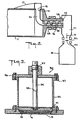
- a portion 10 of a ball mill operable under seal to the atmosphere comprising a hollow rotatable cylindrical shell 11 having end 12 and discharge end 13 and wall 14.
- the shell has discharge ports 15 in the wall, each discharge port being covered, respectively, by a discharge grate 16 across the port to prevent grinding media (not shown), e.g. balls, in the shell from discharging outwardly from the shell.
- a hollow discharge chute 17 is sealed to the outer side of the shell and spirals around the exterior of the mill for about 180°, traversing the shell from end 12 to discharge end 13.
- the chute can spiral less than 180° or more, e.g. it could spiral for 360° around the shell.
- the slope of the side of the chute forms an angle with the horizontal that is greater than the angle of repose of the powder. If this is the case the powder will "fall” down this wall as the mill rotates end thus be carried from the discharge points (grates) to the end of the chute at the discharge end of the mill.
- the chute end blocks further flow and lifts the powder which then "falls” also the discharge conduit 20 (shown in Figure 2).
- the discharge chute and discharge ports are designed so that a series of discharge ports will feed into the discharge chute along the length of the shell, and the grates across the discharge ports are flush with the interior wall (not shown) of the shell.
- Each discharge port is provided with a closure means 30 (a, b and c) having a retractable sealing member 31 for the port.
- the closure means in Figure 1 are shown in the open position 30a with grate exposed and in the closed position 30b as further described below.
- the direction of rotation for discharge is shown by arrow 18.
- FIG. 2 shows discharge chute 17 at the discharge end 19 which is integral with and leads into discharge tube 20, which in turn is located at the receiving end of hollow trunnion 23.
- a valve (not shown) may be provided at entrance port 21 to the discharge conduit 20 to provide a backup to grate seals 31, so that if there is any leakage past the grate seals it will be blocked at this point.
- Discharge conduit 20 is connected to hollow trunnion 23.
- a conveyor type helical discharge screw 25 is affixed in hollow trunnion 23.
- a non-rotating discharge box 27 is sealably connected with rotating seal 28 to the hollow trunnion 23 at end 24 of the trunnion.
- the ball mill is rotated about its substantially horizontal axis by a motor (not shown) through a gear reduction means (not shown).
- An arrow 29 shows direction of powder unloading from the discharge box 27 to a container 41.
- Discharge box 27 is fitted with valve 40 in valve body 40a. Valve 40 is used to protect the atmosphere in the discharge box.
- a discharge receptacle 41 is attached to the discharge box to receive the discharge material from the mill. Alternatively the discharge material can be passed into a conveyor device to transport the discharge material elsewhere.
- a closure means 30 for the grates is shown in cross section in Figure 3, in which an elastomer faced metal plate 31 is sealably placed over grate 16 in the discharge port 15. It will be understood that each discharge port and grate in each discharge chute will have a closure means for sealing the port to the atmosphere.
- the closure means of Figure 3 is sealably mounted on discharge chute wall 32, and plate 31 having an elastomer face 39, shown in the closed position, seals the discharge port 15 having a grate 16 across it, by locking means 33, viz. a threaded section at one end of stem 34.
- the stem 34 is flexibly connected to plate 31. Hole 35 in stem 34 permits plate 31 to be maintained in the open position by means of locking pin 38 (shown in Figure 1).
- Cover plate 36 bolted to flange 37 is removable for inspection and maintenance of the closure means.
- the grate seals e.g. elastomeric faced plates 31
- cover plate 36 of the closure means 30 as shown in the open position of Figure 1
- the mill is then rotated, at below the critical speed for the discharge chute, and as each discharge port successively passes to the bottom of the mill the processed material, e.g. powder, falls out of the mill into the discharge chute. Because there are discharge ports all along the length of the mill, powder is removed all along the mill length. As the mill continues to rotate the powder remains on the outer periphery of the discharge chute and is transported along the mill length to the discharge end of the mill.
- the powder Once the powder has reached the end of the discharge chute it is held there by the end of the discharge chute and lifted by further mill rotation. Once the angle of repose of this collected powder has been reached, it falls into the discharge conduit.
- the powder is thus carried to a chamber in the trunnion provided therefor and is picked up by the conveyer, e.g. a spiral discharge screw. By the rotation of the mill the spiral discharge screw transports the powder through the trunnion and discharges it into the discharge box. The powder then passes into the discharge receptacle 41.
- Mill rotation is continued until all the powder has been discharged from the mill and collected.
- the grate seales are closed, thus isolating the discharge chute from the mill.
- the mill can now be recharged and another milling cycle begun.
- a mill using the present discharge system will contain driving means for rotating the shell, grinding media means to charge the mill and other means to operate the mill and provide a specific atmosphere in the mill are well known to those skilled in the art.
- a valve is placed at the entrance to the discharge conduit. This valve is kept closed during the initial rotation of the mill after the grate seals have been opened. This will blend the initial ultrafine powder with the safer processed powder and significantly reduce the hazard.
- discharge grate and seal assemblies are completely removable from the outside of the discharge chute, making inspection and maintenance of the system possible from outside the mill.
- the entire discharge system can be filled with a gas purging means (not shown in the drawing) so that the entire discharge system can be purged with an inert or other desired gas.
- the present invention can also be used to remove the grindIng media (e.g. balls) from the shell under substantially sealed conditions. This can be achieved by removing one or more of the grates and rotating the mill. The grinding media could be released into a sealed receptacle such as receptacle 41 in Figure 2.
- grindIng media e.g. balls
Landscapes
- Engineering & Computer Science (AREA)
- Food Science & Technology (AREA)
- Crushing And Grinding (AREA)
- Manufacture Of Metal Powder And Suspensions Thereof (AREA)
- Powder Metallurgy (AREA)
- Soil Working Implements (AREA)
- Preparation Of Compounds By Using Micro-Organisms (AREA)
- Heating, Cooling, Or Curing Plastics Or The Like In General (AREA)
- Centrifugal Separators (AREA)
- Winding, Rewinding, Material Storage Devices (AREA)
- Drying Of Solid Materials (AREA)
Priority Applications (1)
| Application Number | Priority Date | Filing Date | Title |
|---|---|---|---|
| AT86301863T ATE62615T1 (de) | 1985-03-15 | 1986-03-14 | Vorrichtung zur entleerung von rotierenden muehlen. |
Applications Claiming Priority (2)
| Application Number | Priority Date | Filing Date | Title |
|---|---|---|---|
| US06/712,704 US4603814A (en) | 1985-03-15 | 1985-03-15 | System for discharging rotary mills |
| US712704 | 1985-03-15 |
Publications (3)
| Publication Number | Publication Date |
|---|---|
| EP0195613A2 EP0195613A2 (en) | 1986-09-24 |
| EP0195613A3 EP0195613A3 (en) | 1987-07-15 |
| EP0195613B1 true EP0195613B1 (en) | 1991-04-17 |
Family
ID=24863202
Family Applications (1)
| Application Number | Title | Priority Date | Filing Date |
|---|---|---|---|
| EP86301863A Expired - Lifetime EP0195613B1 (en) | 1985-03-15 | 1986-03-14 | System for discharging rotary mills |
Country Status (6)
| Country | Link |
|---|---|
| US (1) | US4603814A (enExample) |
| EP (1) | EP0195613B1 (enExample) |
| JP (1) | JPS61213303A (enExample) |
| AT (1) | ATE62615T1 (enExample) |
| CA (1) | CA1244809A (enExample) |
| DE (1) | DE3678739D1 (enExample) |
Families Citing this family (10)
| Publication number | Priority date | Publication date | Assignee | Title |
|---|---|---|---|---|
| JPH0729067B2 (ja) * | 1988-08-26 | 1995-04-05 | 石川島播磨重工業株式会社 | 活性金属の高純度微粉末製造方法 |
| RU2189861C1 (ru) * | 2001-01-12 | 2002-09-27 | Открытое акционерное общество "ТЯЖМАШ" | Стенка торцовая шаровой мельницы |
| RU2190475C2 (ru) * | 2001-01-12 | 2002-10-10 | Открытое акционерное общество "ТЯЖМАШ" | Стенка торцовая шаровой мельницы |
| RU2189276C1 (ru) * | 2001-01-12 | 2002-09-20 | Открытое акционерное общество "ТЯЖМАШ" | Стенка торцовая |
| AU2003246258A1 (en) * | 2002-07-04 | 2004-01-23 | Nissan Chemical Industries, Ltd. | Cerium compound milling method using ball mill |
| US7204439B2 (en) * | 2004-06-21 | 2007-04-17 | Larry Fuller | Apparatus and process for control of rotary breakers |
| ITRE20040086A1 (it) * | 2004-07-16 | 2004-10-16 | Sacmi | Mulino di macinazione discontinuo per materiali ceramici |
| ITRE20050011A1 (it) * | 2005-02-11 | 2006-08-12 | Sacmi | Sistema di collegamento tra mulini continui in serie di un impianto di macinazione |
| US9764329B2 (en) * | 2013-01-15 | 2017-09-19 | Aaron Engineered Process Equipment, Inc. | Rotary mill |
| US10493464B2 (en) | 2014-12-18 | 2019-12-03 | Aaron Engineered Process Equipment, Inc. | Rotary mill |
Family Cites Families (8)
| Publication number | Priority date | Publication date | Assignee | Title |
|---|---|---|---|---|
| US10382A (en) * | 1854-01-03 | Powek-loom | ||
| US2398989A (en) * | 1943-09-01 | 1946-04-23 | Allis Chalmers Mfg Co | Air swept ball mill system |
| US2675967A (en) * | 1949-06-24 | 1954-04-20 | Acheson Colloids Ltd | Discharging or unloading powdered material and the like from rotary mills and the like |
| US3001730A (en) * | 1958-01-24 | 1961-09-26 | Denver Equip Co | Duplicate section grinding mill |
| DE1287913B (enExample) * | 1963-07-25 | |||
| US3441226A (en) * | 1965-07-19 | 1969-04-29 | Camillo Bargero | Cylindrical mill for grinding cement |
| BE785949A (fr) * | 1971-07-06 | 1973-01-08 | Int Nickel Ltd | Poudres metalliques composees et leur production |
| FR2291793A1 (fr) * | 1974-11-20 | 1976-06-18 | Alcan Aluminium France | Procede de broyage de particules de matiere et broyeur a billes perfectionne pour la mise en oeuvre de ce procede |
-
1985
- 1985-03-15 US US06/712,704 patent/US4603814A/en not_active Expired - Lifetime
-
1986
- 1986-03-13 CA CA000504043A patent/CA1244809A/en not_active Expired
- 1986-03-14 EP EP86301863A patent/EP0195613B1/en not_active Expired - Lifetime
- 1986-03-14 JP JP61056752A patent/JPS61213303A/ja active Granted
- 1986-03-14 DE DE8686301863T patent/DE3678739D1/de not_active Expired - Fee Related
- 1986-03-14 AT AT86301863T patent/ATE62615T1/de not_active IP Right Cessation
Also Published As
| Publication number | Publication date |
|---|---|
| CA1244809A (en) | 1988-11-15 |
| EP0195613A2 (en) | 1986-09-24 |
| ATE62615T1 (de) | 1991-05-15 |
| JPH0155899B2 (enExample) | 1989-11-28 |
| DE3678739D1 (de) | 1991-05-23 |
| EP0195613A3 (en) | 1987-07-15 |
| US4603814A (en) | 1986-08-05 |
| JPS61213303A (ja) | 1986-09-22 |
Similar Documents
| Publication | Publication Date | Title |
|---|---|---|
| EP0195613B1 (en) | System for discharging rotary mills | |
| US4887773A (en) | Rotary mill with charging system | |
| US4899901A (en) | Container arranged within a stacking frame | |
| US4801100A (en) | System for discharging ball mills | |
| US5607353A (en) | Airlock system | |
| US4679736A (en) | Rotary mill and a method of charging the mill | |
| US4076044A (en) | Lock chamber for discharging dust | |
| CA1259066A (en) | Rotary mill with charging system | |
| CN1042772A (zh) | 竖炉装料装置 | |
| US4680009A (en) | Apparatus for removing oversize from the hot material discharged from a rotary kiln used to produce sponge iron by a direct reduction of iron oxide containing materials | |
| WO1994009906A1 (en) | Method and device for tubular rotary ball mill or mill with similar grinding instruments | |
| US4653335A (en) | Sampling system for grinding mills | |
| US3206254A (en) | Material handling apparatus | |
| CN210594342U (zh) | 一种可称重的螺杆式粉体定量输送设备 | |
| JPH10167779A (ja) | セメント原料の粉砕・分級装置の鉄分除去装置 | |
| US2675967A (en) | Discharging or unloading powdered material and the like from rotary mills and the like | |
| CN105665109B (zh) | 自动上料枸杞磨粉系统 | |
| GB1586822A (en) | Controlling the corroision of grinding elements in the wet grinding of solid materials | |
| JPS6111844B2 (enExample) | ||
| JPS5914268B2 (ja) | 熱分解残渣の分級および冷却排出装置 | |
| SU1167224A1 (ru) | Поточна лини дл переработки алюминиевых шлаков | |
| JPH0549961A (ja) | 竪型粉砕機 | |
| JP2004073911A (ja) | 竪型ローラミルの粉砕物排出装置 | |
| KR100423437B1 (ko) | 고로 풍구의 더스트 취입장치 | |
| SU1528560A1 (ru) | Устройство дл измельчени материалов |
Legal Events
| Date | Code | Title | Description |
|---|---|---|---|
| PUAI | Public reference made under article 153(3) epc to a published international application that has entered the european phase |
Free format text: ORIGINAL CODE: 0009012 |
|
| AK | Designated contracting states |
Kind code of ref document: A2 Designated state(s): AT DE FR GB IT |
|
| PUAL | Search report despatched |
Free format text: ORIGINAL CODE: 0009013 |
|
| AK | Designated contracting states |
Kind code of ref document: A3 Designated state(s): AT DE FR GB IT |
|
| 17P | Request for examination filed |
Effective date: 19880105 |
|
| 17Q | First examination report despatched |
Effective date: 19890510 |
|
| GRAA | (expected) grant |
Free format text: ORIGINAL CODE: 0009210 |
|
| AK | Designated contracting states |
Kind code of ref document: B1 Designated state(s): AT DE FR GB IT |
|
| REF | Corresponds to: |
Ref document number: 62615 Country of ref document: AT Date of ref document: 19910515 Kind code of ref document: T |
|
| REF | Corresponds to: |
Ref document number: 3678739 Country of ref document: DE Date of ref document: 19910523 |
|
| ET | Fr: translation filed | ||
| ITF | It: translation for a ep patent filed | ||
| PGFP | Annual fee paid to national office [announced via postgrant information from national office to epo] |
Ref country code: FR Payment date: 19920210 Year of fee payment: 7 |
|
| PLBE | No opposition filed within time limit |
Free format text: ORIGINAL CODE: 0009261 |
|
| STAA | Information on the status of an ep patent application or granted ep patent |
Free format text: STATUS: NO OPPOSITION FILED WITHIN TIME LIMIT |
|
| 26N | No opposition filed | ||
| PG25 | Lapsed in a contracting state [announced via postgrant information from national office to epo] |
Ref country code: FR Effective date: 19931130 |
|
| REG | Reference to a national code |
Ref country code: FR Ref legal event code: ST |
|
| PGFP | Annual fee paid to national office [announced via postgrant information from national office to epo] |
Ref country code: AT Payment date: 19970213 Year of fee payment: 12 |
|
| PGFP | Annual fee paid to national office [announced via postgrant information from national office to epo] |
Ref country code: GB Payment date: 19970220 Year of fee payment: 12 |
|
| PGFP | Annual fee paid to national office [announced via postgrant information from national office to epo] |
Ref country code: DE Payment date: 19970224 Year of fee payment: 12 |
|
| PG25 | Lapsed in a contracting state [announced via postgrant information from national office to epo] |
Ref country code: GB Free format text: LAPSE BECAUSE OF NON-PAYMENT OF DUE FEES Effective date: 19980314 Ref country code: AT Free format text: LAPSE BECAUSE OF NON-PAYMENT OF DUE FEES Effective date: 19980314 |
|
| GBPC | Gb: european patent ceased through non-payment of renewal fee |
Effective date: 19980314 |
|
| PG25 | Lapsed in a contracting state [announced via postgrant information from national office to epo] |
Ref country code: DE Free format text: LAPSE BECAUSE OF NON-PAYMENT OF DUE FEES Effective date: 19981201 |
|
| PG25 | Lapsed in a contracting state [announced via postgrant information from national office to epo] |
Ref country code: IT Free format text: LAPSE BECAUSE OF NON-PAYMENT OF DUE FEES;WARNING: LAPSES OF ITALIAN PATENTS WITH EFFECTIVE DATE BEFORE 2007 MAY HAVE OCCURRED AT ANY TIME BEFORE 2007. THE CORRECT EFFECTIVE DATE MAY BE DIFFERENT FROM THE ONE RECORDED. Effective date: 20050314 |