EP0195103B1 - Vertikutiergerät - Google Patents
Vertikutiergerät Download PDFInfo
- Publication number
- EP0195103B1 EP0195103B1 EP85103250A EP85103250A EP0195103B1 EP 0195103 B1 EP0195103 B1 EP 0195103B1 EP 85103250 A EP85103250 A EP 85103250A EP 85103250 A EP85103250 A EP 85103250A EP 0195103 B1 EP0195103 B1 EP 0195103B1
- Authority
- EP
- European Patent Office
- Prior art keywords
- tyne
- tynes
- frame
- aerating machine
- arms
- Prior art date
- Legal status (The legal status is an assumption and is not a legal conclusion. Google has not performed a legal analysis and makes no representation as to the accuracy of the status listed.)
- Expired
Links
Images


Classifications
-
- A—HUMAN NECESSITIES
- A01—AGRICULTURE; FORESTRY; ANIMAL HUSBANDRY; HUNTING; TRAPPING; FISHING
- A01B—SOIL WORKING IN AGRICULTURE OR FORESTRY; PARTS, DETAILS, OR ACCESSORIES OF AGRICULTURAL MACHINES OR IMPLEMENTS, IN GENERAL
- A01B45/00—Machines for treating meadows or lawns, e.g. for sports grounds
- A01B45/02—Machines for treating meadows or lawns, e.g. for sports grounds for aerating
- A01B45/023—Perforators comprising spiking tools actively driven in a reciprocating movement through a crankshaft or eccentric mechanism
Definitions
- the present invention relates to a turf aerating machine as defined by the prior art portion of patent claim 1.
- Prior art turf aerating machines support a plurality of reciprocable tynes adapted to be forced into the ground at regular intervals to aerate the ground.
- These aerators are usually self propelled and include mechanical/hydraulic support means for the tynes, and a timing mechanism which provides a "lost motion" type movement of the tynes such that the tynes reciprocate and engage the ground in a substantially vertical plane as the machine advances.
- the available aerators have been either of very basic form, similar to that. of a reciprocating broad fork in which the tynes extend down from a common reciprocating bar or the like, not giving very satisfactory results, or of complex form, working satisfactorily but being difficult to service and expensive to manufacture.
- tyne arms are formed by push rods, each carrying a hollow tyne, and connecting rods, the push rods being each pivotally connected to the lower end of a connecting rod that, in turn, is connected at its upper end to one crank arm of a crankshaft mounted on the frame of the aerating machine.
- Guide means for the tyne arms are provided in the form of transversely spaced guide sleeves within each of which a tyne arm is slidably mounted for reciprocating movement.
- Each of the guide sleeves is operably connected to a cam actuated mechanism that is driven by a transverse camshaft extending between and suitably journalled on frame members in orderto impart a horizontally reciprocating movement to the guide sleeves and thus to the tynes, the movement being synchronized with the vertical reciprocating movement produced by the camshaft and with the forward driving speed of the aerating machine, so that when the tynes are in a ground penetrating position, the tynes are moved rearwardly at the same speed as the forward travelling speed of the machine and are thus in a horizontally stationary position relative to the ground during penetration.
- the document GB-A-497 277 describes a machine for making holes in the ground, the machine including a set of two tyne arms spaced from each other along the direction of movement of the machine and both tyne arms being operable simultaneously to make two holes at a time.
- the two tyne arms are carried by a carriage which is slidaby supported on a bar, the ends of which are connected to rotating cranks giving the tyne arms a vertically reciprocating motion as the machine moves forward.
- the slidable carriage is connected by a link to the end of an auxiliary crank that is rotatably supported on one of the rotating cranks and has a shorter throw than the rotating crank.
- the link is connected to the carriage through a pin which passes through a slot in the link and is fastened by springs secured at their other ends to the link.
- the aerating machine of the present invention includes means for biasing the tyne arms to the forward end oftheirtravel when thetynes are lifted from the ground.
- the biasing means preferably comprise tension springs, although other biasing means such as pneumatic and hydraulic cylinders, compression springs and resilient rubber or plastics members would also be suitable.
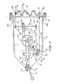
- an aerator 10 in accordance with the present invention has a frame 11 to which are mounted at least two ground engaging wheels 12. These wheels are mounted for rotation about an axle 13 extending tranversely of the aerator 10 and the wheels 12 may function as depth wheels to provide for adjustability of the height at which the aerator 10 travels over the ground.
- the axle 13 may have a cranked portion and the position of this portion relative to the frame 11 may be adjusted to provide for this height adjustment. This adjustment enables the height of the aerator 10 to be varied to achieve varying depth of penetration of the tynes 31 during operation of the aerator 10.
- the aerator 10 has a crankshaft 14 extending transversely of the frame 11.
- the crankshaft 14 is supported by main bearings 15, 16 and 17 and carried by support members 18 integral with the frame 11. Whilst only one crankshaft 14 is illustrated, where a wider aerator is required two crankshafts 14 may be coupled end to end.
- the aertaor 10 includes drive means for rotating the crankshaft 14.
- the drive means illustrated comprises a gearbox 20 having an input shaft 21 and an output shaft 22, the input shaft 21 being capable of being coupled to a power take off of the towing vehicle.
- the gearbox 20 is fixed relative to a mount 23 secured to a member of the frame 11 and the crankshaft 14 may be suitably driven from the gearbox 20 via a drive chain 24 extending over drive sprockets 25, 26. Where there are two crankshafts they may be driven by respective drive chains from the output shaft of the gearbox 20 or alternatively by a duplex chain meshing with respective single sprockets on adjacent ends of the crankshafts.
- the shafts may be driven from their remote ends via suitable drives from spaced take off means on a common shaft or from the opposite ends of a conventional vehicle rigid rear driving axle assembly.
- a chain connection is convenient since it permits the respective crankshafts 14 to be timed with respect to one another to place the throws of one shaft out of phase with the throws of the adjacent shaft. This has the advantage of staggering tyne arms 30 and hence tynes 31 engage the gound in a staggered fashion resulting in smoother operation of the aerator 10.
- crankshaft 14 By using a crankshaft 14 on which the respective cranks are offset with respect to one another, the energy required to drive the tynes 31 into the ground is spread more evenly over the rotational cyle of the crankshaft 14, thereby reducing peak power requirements and reducing the forces applied to the mechanical drive components of the aerator 10.
- Tyne arms 30 are mounted relative to the crankshaft 14 with a bearing 32 located between the upper end of each arm 30 and the crankshaft 14.
- the frame 11 has a transverse frame member 33 formed with a plurality of slots 34 within which the arms 30 are located and travel.
- the arms 30 are biased towards the front of the slots 34 by respective springs 35 and these slots 34 act as guides for fore and aft movement of the arms 30.
- each arm 30 Mounted at the lower end of each arm 30 is a tyne foot 36 which carries at least one tyne 31, however, two or more tynes 31 can be carried by the foot to provide different core patterns or to increase operating speed.
- the foot may be formed integral with the arm 30 althought it is preferred that it be detachable, and to this end the foot may have a sleeve 37 which may be mounted about the lower end of the arm 30 and secured thereto by a clamp.
- the lower end of one of the tyne arms 30 is illustrated in elevation and section plan in Figs. 3 and 4.
- the tyne arm 30 is substantially formed from square section tube.
- a rod 41 is inserted into the lower end of the tyne arm 30 and a flange 42 locates the rod relative to the tyne arm 30.
- the rod 41 is then welded to the tyne arm 30 to form a rigid assembly.
- the lower portion 43 of the rod 41 which projects from the tyne arm 30 provides a stub to which the tyne feet 36 are clamped.
- a first foot 36a comprises a central tube 37 to which are welded a pair of tyne holding tubes 44 into which tynes 31 may be clamped by tightening the respective alien screw 110 which extends through an unthreaded lug 111 and a threaded lug 112 located either side of a slit 113 in the tube 43.
- the tyne holding tubes 44 are sized to closely co-operate with the tynes 31 located therein and have an internal lip 114 at their upper end to prevent slippage of the tyne while it is being inserted into the ground.
- the socket tube 37 is sized to closely co-operate with the stub 43 of the tyne arm 30 to which it is clamped, an allen screw 115 extending through an unthreaded lug 116 and a threaded lug 117 located on either side of slot 118 in the socket 37.
- the transverse spacing S between the tynes 31 will typically be about 50mm.
- Figs. 7 and 8 show a foot 36b having four tynes 31.
- This foot also has a central socket 37 adapted to be clamped to the stub 43 of a tyne arm 30.
- the four tyne holding tubes 44 are joined to the socket 37 by four webs 46 extending radially from the socket 37.
- the transverse spacing S between the tynes of figure 4 is also typically about 50 mm as is the longitudinal pitch P.
- the tynes 31 may either be solid or hollow.
- Each of the tyne holding tubes 44 is preferably provided with a bevelled lower edge 119 such that the "foot print" of the tyne holder is minimized. This has the effect of reducing the amount of soil which builds up on the lower surfaces of the tyne holder.
- the socket 37 preferably has an internally bevelled lower edge 120 and webs 46 of the four tyne holders of Figs. 7 and 8 are also bevelled on their lower edges (not shown).
- the foot can be moved forward after each stroke by distance equal to the number of rows of tynes 31, multiplied by their pitch P, that is, by twice the longitudinal spacing of the tynes 31 in the foot, 36b thereby providing a square grid pattern for aeration.
- the forward speed may be doubled compared to that of a single row tyne arrangement of figure 6 while still providing a square grid aeration pattern. If a square grid pattern is not required the arms 30 can be moved forward by any selected distance between operations.
- a series of buffers 50 mounted at spaced intervals transversely of the aerator 10 are a series of buffers 50, the number of buffers corresponding to the number of tyne arms 30.
- the buffers 50 are mounted on a transverse frame member 51 and each comprises a roller 52 rotatably mounted on support 53 by axle 54.
- the buffers 50 ensure that there is no jarring metal to metal contact during motion. If desired the rear of the slot 34 may also be cushioned in some suitable fashion. It will be seen that each time the arm 30 strikes the buffer 50 the roller 52 presents a different part of its periphery for the next buffering action, thereby increasing the life of the roller 52.
- the rate of the return spring 35 is selected such that during high speed operation the tyne 31 will be brought back into engagement with the ground just before the arm 30 reaches the buffer roller 52, while when the tynes 31 are not engaging the ground, such as when the aerator 10 is lifted clear of the ground during transport, the tyne arm 30 move vertically in one position and roll past the rollers 52.
- the aerator 10 is provided with a guard 60.
- the guard 60 is secured to a member of the frame 11 and extends from this member past the area over which the tynes 31 operate.
- the guard 60 during use, is in contact with the ground and may be biased against it.
- the guard 60 has a forward inclined portion 61 attached to the frame 11 and a rear ground engaging portion 62, the free end of which has a turned up end 63, which enables the aerator 10 to be reversed without the guard 60 prohibiting such movement.
- the rear portion 62 is formed with a series of fingers which when viewed in plan appear as a comb. The respective fingers of this portion extend between adjacent tynes 31 of each foot and between the tynes 31 of adjadent feet to ensure that withdrawal of the tynes 31 does not result in lifting of the turf.
- the operation of the aerator 10 described with reference to Figs. 1 to 9 is as follows.
- the crankshaft 14 is caused to rotate in the direction of arrow A, such that each bearing mount for the tyne arms 30 will sequentially move towards bottom dead centre to engage the tynes 31 in the ground.
- the bearing mount for each tyne arm 30 will move rearwardly relative to the rest of the aerator due to rotation of the crankshaft 14 and at the same time the tyne arm 30 moves along the slots 34 against the action of springs 35 due to its engagement with the ground.
- the frame 11 may be adapted to be supported by a three point linkage with the crankshaft 14 connected to a power take off of a towing vehicle such as a tractor.
- the drive for the crankshaft 14 could be mechanical as illustrated or could be any other suitable drive such as hydraulic.
- a second embodiment of the invention is schematically illustrated wherein means are provided for self propulsion of the aerator.
- the aerator of the second embodiment has a chassis 71 to which are pivotally connected a pair of rearwardly extending arms 72.
- a rear axle is rotatably mounted between the arms 72 and a pair of rear wheels 74, are mounted at the extremities of the axle, outboard of the arms 72.
- a pair of dolly wheels 75 are located centrally of the chassis 71 at the front end thereof.
- the dolly wheels are mounted on the lower end of a vertical steering shaft 76 which is rotatably connected to the chassis 71 and is provided with a tiller 77 pivotably connected to the top end thereof such that the tiller can be folded out of the way when not in use.
- a sprocket 78 on the steering shaft 76 is provided to communicate rotation of a steering wheel 79 to the steering shaft 76, the sprocket 78 being connected to a sprocket 81 fixedly coupled to the steering wheel 79 by a chain 82.
- the steering wheel 79 is located adjacent to a seat 83 which is provided for "ride on” operation, whereas the tiller 77 is provided for "pedestrian" operation.
- the self propelled aerator is also provided with an additional retractable wheel 84 mounted on a pivotable arm 85 and located inboard of the outermost tyne arm 30 such that, with the retractable wheel 84 in its lowered position, the aerator can core right up to the edge of depressions such as sand traps on golf courses and bowling green ditches.
- This feature is not required on the towed embodiment as it can be supported by the three point linkage of the tractor to which it is fitted if one wheel is suspended over the edge of a ditch or sand trap.
- the height of the rear of the self propelled aerator, and therefore the penetration depth of the tynes 31 is adjusted using hydraulic rams 86 connected between the chassis 71 and respective arms 72, while the retractable wheel 84 can be lowered using a hydraulic ram 87 or alternatively it can be lowered by rotation of a threaded rod.
- Power to drive the aerator is provided by an internal combustion engine 88 which would typically provide in the order of eight horsepower.
- a small fuel tank 89 is provided to supply fuel to the engine 88.
- Chain drive a first part of which comprises a sprocket 91 on the engine drive shaft, a chain 92, and a sprocket 93 mounted co-axially with the pivotal mounting point for the arms 72.
- a sprocket 94 connected to sprocket 93 drives a chain 95 which in turn drives a sprocket 96 on the rear axle 73.
- the connection between the sprockets 93 and 94 may be fixed, in which case only one forward speed will be possible, or alternatively the sprockets 93 and 94 may be connected through a gearbox in which case several forward speeds will be possible plus reverse.
- Multiple speeds can also be provided by providing a plurality of parallel chain drives each having a different sprocket ratio and each being provided with a clutch to allow selective engagement of one chain drive. It will be recognized that when reference is made to a drive speed of the aerator it is actually the ratio of forward speed to tyne operating speed which is referred to, and it is this ratio which determines the core pattern achieved by the machine. Absolute forward speed can be controlled by controlling the throttle of the engine 88 and a differential may also be provided on the rear axle or in the hub of one of the rear wheels 74 to simplify turning of the aerator.
- the pressure to operate the hydraulic cylinders 86 and 87 is provided by a hydraulic pump 97 which is driven from engine 88 thorugh a V-belt 98 and a pair of pulleys 99, 100.
- the tyne arm drive of Figs. 3,10 and 11 is essentially identical to that described with reference to Figs. 1 to 9 and will not be described in detail.
- the crankshaft 14 of the tyne arm drive is driven via a chain 101 which drives sprocket 25 and is driven by sprocket 102 mounted on a transverse shaft 103 having a sprocket 104 fitted to its other end.
- the sprocket 104 is in turn driven by chain 105 and sprocket 106 fitted to the drive shaft of engine 88.
Claims (14)
Priority Applications (3)
| Application Number | Priority Date | Filing Date | Title |
|---|---|---|---|
| DE8585103250T DE3573506D1 (en) | 1985-03-20 | 1985-03-20 | Improved turf aerator |
| EP85103250A EP0195103B1 (de) | 1985-03-20 | 1985-03-20 | Vertikutiergerät |
| US06/715,463 US4658909A (en) | 1985-03-20 | 1985-03-25 | Vehicle mounted aerating machine |
Applications Claiming Priority (1)
| Application Number | Priority Date | Filing Date | Title |
|---|---|---|---|
| EP85103250A EP0195103B1 (de) | 1985-03-20 | 1985-03-20 | Vertikutiergerät |
Publications (2)
| Publication Number | Publication Date |
|---|---|
| EP0195103A1 EP0195103A1 (de) | 1986-09-24 |
| EP0195103B1 true EP0195103B1 (de) | 1989-10-11 |
Family
ID=8193386
Family Applications (1)
| Application Number | Title | Priority Date | Filing Date |
|---|---|---|---|
| EP85103250A Expired EP0195103B1 (de) | 1985-03-20 | 1985-03-20 | Vertikutiergerät |
Country Status (3)
| Country | Link |
|---|---|
| US (1) | US4658909A (de) |
| EP (1) | EP0195103B1 (de) |
| DE (1) | DE3573506D1 (de) |
Cited By (1)
| Publication number | Priority date | Publication date | Assignee | Title |
|---|---|---|---|---|
| WO2008101292A1 (en) * | 2007-02-22 | 2008-08-28 | Greencare Industries Pty Ltd | 'aerator mechanism with vertically reciprocating tine' |
Families Citing this family (29)
| Publication number | Priority date | Publication date | Assignee | Title |
|---|---|---|---|---|
| US4750565A (en) * | 1985-01-16 | 1988-06-14 | Outboard Marine Corporation | Turf aerating apparatus |
| NZ221176A (en) * | 1987-07-23 | 1989-10-27 | Brian John Rohleder | Ground coring and aerating apparatus: skid guides uplifted soil back down |
| JPH01101802A (ja) * | 1987-10-14 | 1989-04-19 | Tonami Seisakusho:Kk | グリーンリフレッシャー |
| US4867244A (en) * | 1987-11-16 | 1989-09-19 | Outboard Marine Corporation | Turf aerating apparatus |
| US4901655A (en) * | 1987-12-11 | 1990-02-20 | Lawn Doctor, Inc. | Cultivator |
| US4819734A (en) * | 1988-03-15 | 1989-04-11 | Classen Alvin T | Lawn aerator with rocker arm tine synchronizing means |
| US5398767A (en) * | 1988-06-22 | 1995-03-21 | Warke; William L. | Ground treatment apparatus |
| WO1989012381A2 (en) * | 1988-06-22 | 1989-12-28 | Warke William L | Grass treatment apparatus |
| US4930604A (en) * | 1988-10-31 | 1990-06-05 | United Technologies Corporation | Elevator diagnostic monitoring apparatus |
| JPH0640764B2 (ja) * | 1988-11-08 | 1994-06-01 | 株式会社ティー・ジィー・ワイ | グリーン用コア回収装置 |
| GB2225692B (en) * | 1988-12-07 | 1993-04-28 | Sisis Equip | A mobile turf drilling machine |
| GB2233537A (en) * | 1989-07-04 | 1991-01-16 | Sisis Equip | Apparatus for preparing turf for seeding |
| US5207278A (en) * | 1992-04-13 | 1993-05-04 | Textron Inc. | Turf aerator |
| GB2290692B (en) * | 1994-07-02 | 1997-09-24 | Sisis Equip | A device for cutting slots in turf |
| AUPN642695A0 (en) * | 1995-11-08 | 1995-11-30 | Deere & Company | Cultivating machine |
| US6505687B1 (en) | 2000-03-10 | 2003-01-14 | Paul Wichmann | Abrading tine for turf aeration apparatus |
| US6948568B2 (en) | 2001-04-06 | 2005-09-27 | Deere & Company | Cultivator for aerating a ground surface |
| DE50312022D1 (de) * | 2002-05-15 | 2009-11-26 | Wiedenmann Gmbh | Bodenbearbeitungsgerät |
| WO2004043132A2 (en) * | 2002-11-12 | 2004-05-27 | The Toro Company | Walk aerator with ground following coring head, inboard wheels, assembled multi-part crankshaft, integral core deflectors, and shortened coring head depth |
| EP1543709A1 (de) * | 2003-12-19 | 2005-06-22 | Wiedenmann GmbH | Bodenbearbeitungsgerät |
| US20060070749A1 (en) * | 2004-09-13 | 2006-04-06 | American-Iowa Manufacturing, Inc. | Turf maintenance device for aeration and vertical cutting of soil |
| DE102005055289B3 (de) * | 2005-11-21 | 2007-03-22 | Wiedenmann Gmbh | Bodenbearbeitungsgerät mit Kurbelschutz |
| EP1967055A1 (de) | 2007-03-06 | 2008-09-10 | Redexim Handel-en Exploitatie Maatschappij B.V. | Bodenbearbeitungsvorrichtung |
| EP2070402B1 (de) * | 2007-12-13 | 2019-08-28 | Redexim Handel-en Exploitatie Maatschappij B.V. | Bodenbelüftungsvorrichtung |
| US7971653B2 (en) | 2009-06-10 | 2011-07-05 | Deere & Company | Aerator with hole spacing control system |
| US8757283B2 (en) * | 2012-03-22 | 2014-06-24 | Elmer A. Wessel | Aerator |
| EP2944167B1 (de) * | 2014-05-16 | 2018-11-28 | Redexim Handel- En Exploitatie Maatschappij B.V. | Bodenbearbeitungsvorrichtung |
| DE102016103853A1 (de) * | 2016-03-03 | 2017-09-07 | Novokraft Ag | Bodenbehandlungsvorrichtung, Bodenbehandlungssystem sowie Rohrleitung und/oder elektrische Leitung |
| US10779454B2 (en) | 2018-01-30 | 2020-09-22 | Exmark Manufacturing Company, Incorporated | Soil penetrating apparatus with depth control |
Family Cites Families (16)
| Publication number | Priority date | Publication date | Assignee | Title |
|---|---|---|---|---|
| US1853079A (en) * | 1928-12-19 | 1932-04-12 | Thomas G Plant | Machine for seeding golf links, lawns, and the like |
| US2056337A (en) * | 1935-06-21 | 1936-10-06 | John F Archibald | Lawn spiker |
| GB497277A (en) * | 1937-06-15 | 1938-12-15 | Gerald Brown | Improvements in or relating to agricultural machines for piercing the soil |
| GB661287A (en) * | 1948-12-10 | 1951-11-21 | Rose Brothers Ltd | Improvements in turf piercing machines |
| US2730028A (en) * | 1951-02-20 | 1956-01-10 | Harry L Oswalt | Turf perforator |
| US3490540A (en) * | 1967-03-06 | 1970-01-20 | Clifford S West | Aerator having spring mounted tines |
| NL6807548A (de) * | 1968-05-29 | 1969-12-02 | ||
| US3743025A (en) * | 1970-07-01 | 1973-07-03 | R Thatcher | Reciprocating soil aerator with flexible tool guide assembly |
| GB1347967A (en) * | 1971-06-14 | 1974-02-27 | Sisis Equipment Macclesfield | Turf piercing machines |
| ZA726410B (en) * | 1971-09-29 | 1973-06-27 | Scott Bonnar Ltd | Turf aerating machine |
| US3834464A (en) * | 1973-02-27 | 1974-09-10 | Outboard Marine Corp | Aerating machine |
| US3926131A (en) * | 1973-03-29 | 1975-12-16 | William C Collins | Injector for soil treating liquids |
| US4084642A (en) * | 1976-07-13 | 1978-04-18 | Killion Marvin L | Turf perforating machine |
| US4154305A (en) * | 1977-11-30 | 1979-05-15 | Prewett Jesse L | Aerator apparatus |
| US4212357A (en) * | 1978-02-01 | 1980-07-15 | Outboard Marine Corporation | Turf aerating device |
| US4569400A (en) * | 1984-04-30 | 1986-02-11 | Fuji Trailer Manufacturing Co., Ltd. | Driller for use in rice field |
-
1985
- 1985-03-20 DE DE8585103250T patent/DE3573506D1/de not_active Expired
- 1985-03-20 EP EP85103250A patent/EP0195103B1/de not_active Expired
- 1985-03-25 US US06/715,463 patent/US4658909A/en not_active Expired - Lifetime
Cited By (1)
| Publication number | Priority date | Publication date | Assignee | Title |
|---|---|---|---|---|
| WO2008101292A1 (en) * | 2007-02-22 | 2008-08-28 | Greencare Industries Pty Ltd | 'aerator mechanism with vertically reciprocating tine' |
Also Published As
| Publication number | Publication date |
|---|---|
| US4658909A (en) | 1987-04-21 |
| DE3573506D1 (en) | 1989-11-16 |
| EP0195103A1 (de) | 1986-09-24 |
Similar Documents
| Publication | Publication Date | Title |
|---|---|---|
| EP0195103B1 (de) | Vertikutiergerät | |
| US4632189A (en) | Soil aerating machine | |
| US4753298A (en) | Turf aerating apparatus | |
| US4750565A (en) | Turf aerating apparatus | |
| US4867244A (en) | Turf aerating apparatus | |
| US4602687A (en) | Drive mechanism for turf aerating apparatus | |
| US4662456A (en) | Self-propelled lawn aeration machine | |
| EP0853869B1 (de) | Bodenbelüfter | |
| US4926947A (en) | Turf aerating apparatus with resilient handle mount | |
| US4645012A (en) | Turf aerating apparatus | |
| US2638831A (en) | Groundworking machine | |
| CA2140350C (en) | Soil compaction | |
| US5178221A (en) | Core-gathering apparatus and a main conveyor belt drive roller structure for the apparatus | |
| US6612773B2 (en) | Rumble strip cutter | |
| CA1232787A (en) | Turf aerator | |
| NZ211855A (en) | Turf aerator tyne drive | |
| US4236582A (en) | Powered ground aerator | |
| US4884637A (en) | Ground/turf aerator | |
| US2193575A (en) | Turf spiking tool | |
| JPH0728566B2 (ja) | 芝生用空気混和装置 | |
| CN210120787U (zh) | 履带式鱼腥草联合收获机 | |
| CN1032511C (zh) | 人力自动栽秧机 | |
| AU664692B2 (en) | Drive linkage for agricultural device | |
| CN108307704B (zh) | 一种大棚免掉头往复起垄机 | |
| CN219152033U (zh) | 一种不锈钢焊管生产用自动化焊接设备 |
Legal Events
| Date | Code | Title | Description |
|---|---|---|---|
| PUAI | Public reference made under article 153(3) epc to a published international application that has entered the european phase |
Free format text: ORIGINAL CODE: 0009012 |
|
| AK | Designated contracting states |
Kind code of ref document: A1 Designated state(s): BE DE FR GB IT NL SE |
|
| 17P | Request for examination filed |
Effective date: 19870306 |
|
| 17Q | First examination report despatched |
Effective date: 19880323 |
|
| GRAA | (expected) grant |
Free format text: ORIGINAL CODE: 0009210 |
|
| AK | Designated contracting states |
Kind code of ref document: B1 Designated state(s): BE DE FR GB IT NL SE |
|
| ITF | It: translation for a ep patent filed |
Owner name: BARZANO' E ZANARDO MILANO S.P.A. |
|
| ET | Fr: translation filed | ||
| REF | Corresponds to: |
Ref document number: 3573506 Country of ref document: DE Date of ref document: 19891116 |
|
| PLBE | No opposition filed within time limit |
Free format text: ORIGINAL CODE: 0009261 |
|
| STAA | Information on the status of an ep patent application or granted ep patent |
Free format text: STATUS: NO OPPOSITION FILED WITHIN TIME LIMIT |
|
| 26N | No opposition filed | ||
| ITTA | It: last paid annual fee | ||
| EAL | Se: european patent in force in sweden |
Ref document number: 85103250.8 |
|
| PGFP | Annual fee paid to national office [announced via postgrant information from national office to epo] |
Ref country code: NL Payment date: 19970429 Year of fee payment: 13 |
|
| PGFP | Annual fee paid to national office [announced via postgrant information from national office to epo] |
Ref country code: SE Payment date: 19970502 Year of fee payment: 13 |
|
| PGFP | Annual fee paid to national office [announced via postgrant information from national office to epo] |
Ref country code: BE Payment date: 19970521 Year of fee payment: 13 |
|
| PG25 | Lapsed in a contracting state [announced via postgrant information from national office to epo] |
Ref country code: SE Free format text: LAPSE BECAUSE OF NON-PAYMENT OF DUE FEES Effective date: 19980321 |
|
| PG25 | Lapsed in a contracting state [announced via postgrant information from national office to epo] |
Ref country code: BE Free format text: LAPSE BECAUSE OF NON-PAYMENT OF DUE FEES Effective date: 19980331 |
|
| BERE | Be: lapsed |
Owner name: GREENCARE PTY. LTD Effective date: 19980331 |
|
| PG25 | Lapsed in a contracting state [announced via postgrant information from national office to epo] |
Ref country code: NL Free format text: LAPSE BECAUSE OF NON-PAYMENT OF DUE FEES Effective date: 19981001 |
|
| NLV4 | Nl: lapsed or anulled due to non-payment of the annual fee |
Effective date: 19981001 |
|
| EUG | Se: european patent has lapsed |
Ref document number: 85103250.8 |
|
| PGFP | Annual fee paid to national office [announced via postgrant information from national office to epo] |
Ref country code: FR Payment date: 20000426 Year of fee payment: 16 |
|
| PGFP | Annual fee paid to national office [announced via postgrant information from national office to epo] |
Ref country code: DE Payment date: 20000427 Year of fee payment: 16 |
|
| PG25 | Lapsed in a contracting state [announced via postgrant information from national office to epo] |
Ref country code: FR Free format text: LAPSE BECAUSE OF NON-PAYMENT OF DUE FEES Effective date: 20011130 |
|
| REG | Reference to a national code |
Ref country code: FR Ref legal event code: ST |
|
| PG25 | Lapsed in a contracting state [announced via postgrant information from national office to epo] |
Ref country code: DE Free format text: LAPSE BECAUSE OF NON-PAYMENT OF DUE FEES Effective date: 20020101 |
|
| REG | Reference to a national code |
Ref country code: GB Ref legal event code: IF02 |
|
| PGFP | Annual fee paid to national office [announced via postgrant information from national office to epo] |
Ref country code: GB Payment date: 20020916 Year of fee payment: 18 |
|
| PG25 | Lapsed in a contracting state [announced via postgrant information from national office to epo] |
Ref country code: GB Free format text: LAPSE BECAUSE OF NON-PAYMENT OF DUE FEES Effective date: 20030320 |
|
| GBPC | Gb: european patent ceased through non-payment of renewal fee |
Effective date: 20030320 |