US1853079A - Machine for seeding golf links, lawns, and the like - Google Patents
Machine for seeding golf links, lawns, and the like Download PDFInfo
- Publication number
- US1853079A US1853079A US327084A US32708428A US1853079A US 1853079 A US1853079 A US 1853079A US 327084 A US327084 A US 327084A US 32708428 A US32708428 A US 32708428A US 1853079 A US1853079 A US 1853079A
- Authority
- US
- United States
- Prior art keywords
- seed
- machine
- soil
- devices
- granulating
- Prior art date
- Legal status (The legal status is an assumption and is not a legal conclusion. Google has not performed a legal analysis and makes no representation as to the accuracy of the status listed.)
- Expired - Lifetime
Links
- 238000010899 nucleation Methods 0.000 title description 33
- 239000002689 soil Substances 0.000 description 112
- 238000002156 mixing Methods 0.000 description 60
- 244000025254 Cannabis sativa Species 0.000 description 27
- 230000003750 conditioning effect Effects 0.000 description 26
- 230000007246 mechanism Effects 0.000 description 20
- 235000021384 green leafy vegetables Nutrition 0.000 description 16
- 239000000203 mixture Substances 0.000 description 15
- 238000010298 pulverizing process Methods 0.000 description 15
- 239000008187 granular material Substances 0.000 description 12
- 239000002131 composite material Substances 0.000 description 11
- 230000000694 effects Effects 0.000 description 10
- 230000009471 action Effects 0.000 description 9
- 238000000034 method Methods 0.000 description 9
- 238000010276 construction Methods 0.000 description 8
- 230000001143 conditioned effect Effects 0.000 description 7
- 241000196324 Embryophyta Species 0.000 description 5
- 238000000151 deposition Methods 0.000 description 5
- 238000005469 granulation Methods 0.000 description 4
- 230000003179 granulation Effects 0.000 description 4
- 238000004519 manufacturing process Methods 0.000 description 4
- 238000005266 casting Methods 0.000 description 3
- 238000007906 compression Methods 0.000 description 3
- 230000006835 compression Effects 0.000 description 3
- 230000000979 retarding effect Effects 0.000 description 3
- KUGRPPRAQNPSQD-UHFFFAOYSA-N OOOOO Chemical compound OOOOO KUGRPPRAQNPSQD-UHFFFAOYSA-N 0.000 description 2
- 238000006073 displacement reaction Methods 0.000 description 2
- 230000001788 irregular Effects 0.000 description 2
- 230000000149 penetrating effect Effects 0.000 description 2
- 241000239290 Araneae Species 0.000 description 1
- OZBZONOEYUBXTD-UHFFFAOYSA-N OOOOOOOOO Chemical compound OOOOOOOOO OZBZONOEYUBXTD-UHFFFAOYSA-N 0.000 description 1
- UIQWBVPFHHQZHH-UHFFFAOYSA-N OOOOOOOOOOOOOO Chemical compound OOOOOOOOOOOOOO UIQWBVPFHHQZHH-UHFFFAOYSA-N 0.000 description 1
- RRCYYLHJWRYWEI-UHFFFAOYSA-N OOOOOOOOOOOOOOOOOOOOO Chemical compound OOOOOOOOOOOOOOOOOOOOO RRCYYLHJWRYWEI-UHFFFAOYSA-N 0.000 description 1
- 208000027418 Wounds and injury Diseases 0.000 description 1
- 230000008901 benefit Effects 0.000 description 1
- 230000008859 change Effects 0.000 description 1
- 230000006378 damage Effects 0.000 description 1
- 230000001419 dependent effect Effects 0.000 description 1
- 238000005553 drilling Methods 0.000 description 1
- 238000007667 floating Methods 0.000 description 1
- 230000000266 injurious effect Effects 0.000 description 1
- 208000014674 injury Diseases 0.000 description 1
- 239000000463 material Substances 0.000 description 1
- 238000005065 mining Methods 0.000 description 1
- 238000005096 rolling process Methods 0.000 description 1
- 238000009331 sowing Methods 0.000 description 1
- 238000009827 uniform distribution Methods 0.000 description 1
Images


Classifications
-
- A—HUMAN NECESSITIES
- A01—AGRICULTURE; FORESTRY; ANIMAL HUSBANDRY; HUNTING; TRAPPING; FISHING
- A01B—SOIL WORKING IN AGRICULTURE OR FORESTRY; PARTS, DETAILS, OR ACCESSORIES OF AGRICULTURAL MACHINES OR IMPLEMENTS, IN GENERAL
- A01B45/00—Machines for treating meadows or lawns, e.g. for sports grounds
- A01B45/02—Machines for treating meadows or lawns, e.g. for sports grounds for aerating
- A01B45/023—Perforators comprising spiking tools actively driven in a reciprocating movement through a crankshaft or eccentric mechanism
-
- Y—GENERAL TAGGING OF NEW TECHNOLOGICAL DEVELOPMENTS; GENERAL TAGGING OF CROSS-SECTIONAL TECHNOLOGIES SPANNING OVER SEVERAL SECTIONS OF THE IPC; TECHNICAL SUBJECTS COVERED BY FORMER USPC CROSS-REFERENCE ART COLLECTIONS [XRACs] AND DIGESTS
- Y10—TECHNICAL SUBJECTS COVERED BY FORMER USPC
- Y10S—TECHNICAL SUBJECTS COVERED BY FORMER USPC CROSS-REFERENCE ART COLLECTIONS [XRACs] AND DIGESTS
- Y10S111/00—Planting
- Y10S111/901—Lawn or turf
Definitions
- This invention relates to a method of and machine for conditioning and grass seedlng ground,and is more particularlydirected to such a method vand'machine for the production andrenovation of golf links fairwa s, putting greens, lawns andthe like.
- olf links are valued largely by the fine texture of the turf and uniform growth of grass, especially in the putting greens, fairways, and the like, and attempts have been made heretofore to secure'an acceptable and uniform turf texture by manual efforts seeking to disintegrate the surface soil by harrow and hand rake, then scatter the grass seed over the soil, and, in a subsequent effort, hand rake the scattered seed and surface soil.
- Grass seed of the fine character required to produce the desired 5 fine turf texture is readily influenced by'air currents and when scattered about is found tobe deposited on the soil in irregular batches and amounts dependent upon the individual and Wind conditions, with the result that when attempt is made to rake it into the soil only a small portion in irregular batches is covered so that when the grass comes up the irregularity of growth of grass will be manifested throughout the seeded area.
- sowing grain a drilling or harrowing action is employed, either to form rows into which the seedis depositedand thereafter-"covered, or
- the ground to be grass seeded is first surface granulated or pulverized in place and'fine grass seed is then uniformly broadcasted on to the granulated surface soil the seed and granulated soil are then-inter mixed resulting in a lightsoil covering'the seed, and immediately thereafter the mixed seed and soil are subjected to compression whereby the uniformly broadcasted seed and granulated surface soil remain relatively fixed and undisturbed by wind, rain or other natural conditions.
- the operations constia tuting the method of the present invention are carried on in continuous consecutive sequence,
- the soil is first granulated or pulverized, the seed uniformly roadcasted close to the surface of the granulated soil, and the broadcasted seed and granulated soil immediately thereafter being intermixed by the rear pulverizing and mixing devices.
- the compression to which the mixed seed and granulated soil are subjected is conveniently carried into effect by means of a trailing roller which acts upon the intermixed granulated soil and seed immediately after the intermixture of the two.
- the machine for carrying the method into effect is provided with means for imparting to the pulverizing or granulating devices a rapid up-and-down movement whereby the granulating or pulverizing devices act upon the surface soil in place, while the rear pulverizing and mixing evices for intermixing the broadcasted seed and granulated soil are likewise actuated by a train of mechanism for imparting rapid upand-down movements thereto, the result being that the fine seed broadcasted between the granulating devices and surface mixing devices is intermixed with the granulated soil without the production of uneven or furrowed conditions.
- the machine of the present invention be moved over the ground to be seated at a relatively slow speed and yet be susceptible of a higher advancing speed when the seeding operation has been concluded on any particular ground area, and to this end the machine of the present invention is provided with a motor and trains of mechanism actuated therefrom to advance the machine at slow speed during the seeding operation and when the seeding operation has been concluded on any particular area, and the granulating or pulverizing and mixing devices have been moved to their inoperative position under manual control, the machine will be advanced at higher speed.
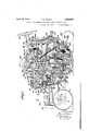
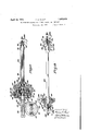
- Fig. 1 is a side elevation of the complete machine containing the present invention
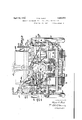
- Fig. 2 is a front elevation of the machine, some of the parts being shown in section;
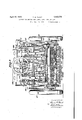
- Fig. 3 is a rear elevation of the machine with the trailing roller omitted;
- Fig. 4 is an enlarged detail with parts in section showing theseed hopper and associated parts;
- Fig. 5 is a perspective view on an enlarged scale of one group of granulating or pulverizing devices and mixing devices and means for operating them;
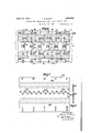
- Fig. 6 is a top plan view of the entire group of granulating and mixing devices showing more particularly the guiding means and manner of nesting these devices in groups;
- Fig. 7 is a top plan view of the seed broadcasting plate
- Fig. 7a is an enlarged section on the line 7 7 of Fig. 7, and showing more particularly one good form of means for broadcasting the seed as delivered from the hopper;
- Fig. 8 is adetached side elevation with some of the parts in section, showing more particularly the manual control of the granulating and mixing devices;
- Fig. 9 is a top plan view on a small scale of the front wheels of the machine frame and connected steering mechanism thereof;
- Fig. 10 is a detached side elevation of mechanism for Varying the speed at which the machine may be advanced;
- Fig. 11 is a sectional elevation through the speed controlling mechanism.
- Fig. 12 is a detached view with parts in section showing clutch means for connecting and disconnecting the driving wheels with the motor.
- the various operating parts of the conditioning and seeding machine are mounted upon a frame work or carriage that is adapted to travel over the ground by motor means mounted upon the carriage or frame work.
- the frame of the machine may be variously constructed to appropriately support the operating parts and, as indicated in the present instance of the invention, it consists of side frames 1 connected by the cross-ties 2 and angle plates 3, Fig. l, and extending frontward of the machine frame are the plates or castings 4, Figs. 1 and 2, to which the front axle 5 is connected by means of a fifth wheel 6 which may be secured to the front castings 4 by a pivot pin 7.
- Mounted on the front axle 5 are the front wheels 8 which are preferably formed of a width to impart no injurious influence to the ground over which the machine is traveled.
- the rear wheel shaft 9, Fig. 1 Extending between the side frames 2 and suitably journalled therein is the rear wheel shaft 9, Fig. 1, on which are mounted the rear wheels 10, of which there may be two, one at each side of the machine.
- the wheels which support a large part of the weight of the machine .may'be suitably formed to prevent injury. to, theground, as by having 'manipulation by the machine attendant, and
- a sprocketwheel14 at its oppositeend. Passing about the sprocket wheel 14 is the sprocket chain 15 which. encircles a sprocketwheel 16 mounted. for rotative movement upon a pin :17 extending from one of the frames 2 at one side of the machine, and secured: to
- the sprocket wheel 16 is the downwardly extending; arm- 18 I which is connected at its lower end'at19 to a linki20 projecting laterally from the arm 18 and connected at its opposite end by the pivot 21, Fig. 9, to a steering arm? 22 'operatively associated with the fifth wheel mechanism to change the direction' of. themachine as it is advanced.
- the supporting and steering mechanism for the machine may be variously contrived, but the above'co nstitutesone good practical form of the invention in this respect.
- extension 4 of the machine frame is the motor 23, Fig. 1,
- the drive shaft 28 whichis mounted for slight'endwise movement, and on the forwardly extending end of the driveshaft 28 is a worm 29 which meshes with aworm wheel 30, the construction be ing such that upon-rotative movement being imparted to the drive shaft 28, the worm wheel 30 will. be given rotary movement.
- Loosely mounted upon the drive shaft 28 is the casing 31 having a hub portion 32 to which is secured a gear 33, and rotary movement is imparted tothecasing31 by a silent chain drive 34 between the motor shaft 24 and the sprocketed portion 35 of the casing 31.
- the gear 36 Secured to the drive shaft 28 is the gear 36 which may be conveniently mounted on the hub 37 secured to the shaft-by a key'38.
- the composite collar 39 Mounted for rotative movement about the shaft 28 is the composite collar 39, the two parts of which rotate together, and extending from the collar 39 are the pins 40, each of which carries the difierential gears 41 and 42,.the formerbeingin mesh with the fixed gear 36 and the latter with the gear 33 carried by the loose casing 31.
- the mechanism described is of the differential, type suchthat in'suitable bearings 27 at the upi on: rotativemovement of the-loose casing 31, rotative movement will be imparted to the shaft 28 by the differential character or size of the gears 41 and Y42 and the speed of rotation of the shaft will .ofcourse be governed by. the freedom to rotary movement of the compositecollar 39. That is.
- the difierential thus far described may beof any usual type and-retardation ofthe rotative movement of'one of the parts of the differential, such, for instance, as the composite collar 39, is controlled in accordance with the present invention to. vary the speed .of the drive shaft 28 and of course the mechanism driven thereby.
- the worm wheel 30 is drivenfrom the worm .29 and consequently partakes of the speed of rotation of the drive shaft 28.
- V he worm wheel 30 has a hub portion 43 loosely mounted on thetraction shaft 44, Fig. 12, and carries the floating bevelled gears 45 which are disposed between the, fixed bevelgear 46 secured to the traction shaft 44 and the loose bevel-gear 47, constituting-in'efiect a differential movement of generally well understood character.
- the loose bevel-gear 47 has a hub portion 48 on which is loosely mounted the sprocket wheel 49 which may be clutched to and re: leased from the bevel-gear 47 by movement of a clutch key 50 normally under the influence of a-spring 51 to position the parts 54 and having a clutch recess 55.
- Loosely mounted on the hub portion 56 of the clutch disk 53 is the sprocket wheel 57 which may be clutched to the clutch disk 53'by the key 58 under the influence ofa spring 59, in a manner similar as described already for the opposite end of the shaft, Fig. 12.
- each; of the sprocket wheels 49 and 57 passes a sprocket chain 60 connected to its associated driving wheel by a sprocket wheel 61, as more clearly indicated in Fig. 1, i
- the mechanism described as an embodiment of this feature of the invention to propel the machine constitutes one good practical form of means to this end, but may be variously contrived to cause the machine to be advanced and at the sime time permit the main supporting wheels to rotate at different speeds as the machine is deflected from a straight course.
- the present invention proposes to construct and associate the devices as will now be described.
- a head 62 Mounted upon the frame for up-and-down reciprocating movement is a head 62 having a front portion 63 on which are mounted a series or gang of granulating or pulverizing devices 64, shown in the present instance of the invention as being constituted as plungers arranged in staggered relation and under spring action to yield in case any of the plungers should strike an obstruction in the surface soil.
- a series or gang of granulating or pulverizing devices 64 shown in the present instance of the invention as being constituted as plungers arranged in staggered relation and under spring action to yield in case any of the plungers should strike an obstruction in the surface soil.
- the front portion 63 of the head has a series of openings through which the granulating devices extend, and since each of the granulating devices is a duplicate of the other, a description of one will be suilicient for all.
- the granulating devices as indicated more clearly on an enlarged scale in Fig.
- the rear portion 70 of the head may be formed of substantially the same construction as described for the front or leading portion of the head, and mounted in the rear portion of the head are a series of mixing devices 71 which like the granulating devices may be formed as plungers and guided by the lower and up aer plates of the head in a manner substantially the same as that for the granulating devices.
- each of the mixing devices 71 is provided with a collar 7 2 of substantial size to maintain the mixing device from penetrating the soil to as great an extent as the first set of granulating devices, and each of the devices is provided with spring means to premit yielding upward movement should any one of them strike an obstruction in the soil.
- the means to this end as herein shown consists of springs 73 interposed between the top plate 74 and the collar 7 2.
- each of the top plates 67 and 74 are connected to the bottom plates by a threaded bolt 75 having a head 76 for turning the bolt, and a locking device 77 for holding the bolt in its adjusted position.
- a threaded bolt 75 having a head 76 for turning the bolt, and a locking device 77 for holding the bolt in its adjusted position.
- Each of the heads 62 is provided with a yoke 78 at its upper portion, to which is pivotally connected a link 79, the upper end of which is pivotally secured at 80 to an operating lever 81 pivotally mounted on the crossshaft 82.
- the number of heads employed will of course dictate the number of levers for operating them.
- Each of the lovers 81 is provided with a roll 83 normally maintained in contact with its associated cam 84 by means of a spring 85, the upper end portion of which is connected to the lever 81 at 86 and the lower end of which is secured to the cross-bar 87, as indicated in Figs. 1 and 8.
- the head actuating cams 84 are mounted upon the cam shaft 88 extending trans versely of the machine and driven by a train of mechanism actuated from the driving shaft 28.
- the driving shaft 28 which has a slight endwise movement as hereinbefore stated, is surrounded by a sleeve 89 carrying a bevel-gear 90 and bearing against a thrust bearing 91.
- the sleeve 89 carrying a bevel-gear 90 and bearing against a thrust bearing 91.
- the cam shaft 88 has a bevel-gear 94, Fig, 3, which engages the bevel-gear 90 on the sleeve 89,'the construction being'such that when the sleeve is rotated under the conditions above noted, the cam shaft will be-actuated to turn the series of cams thereon and lift the head or-heads connected-to the respective operating levers,- and such levers and perforce the head or heads will'be lowered rapidly under the stress of the springs 85, thereby forcing the granulating and mixing pulverizers downwardly in the performance of their respective functions. 7
- the reciprocating up and down movements of the head or heads 62 are controlled andguided by'a slot formed inthe downwardly extending portion of the yoke 7 8 which embraces the wheel shaft 9, and each ofthe headsis provided with front and rear guideflanges 96 and '97, Figs. 1 and 5, which bear upon the adjacent rolls 98 and 99 mounted upon transverse shafts 100 and 10.1.
- the head carrying-thegranulating and the mixing devices should be given a very rapid reciprocating move- V and mixing pulverizer tools are employed in associated relation transversely of the ment to thereby insure granulation of the soil in place and a proper mixing 1ofthe broadcasted seed and granulated soil, and while the means hereinbefore described con- I stitutes a good-form of this feature of the' that the detailsthereof'may be varied indefinitely.
- each of the heads has interengaging edge portions with the adjacent head, while the end member of 1 the gang oftools is guided guide strips;
- the fine grass seed is to'be broadcasted upon the granulated soil immediately after its granulation
- the present invem in order to broadcast the seed between the two sets of devices, the present invem.
- tion' provides a broadcasting plate 103 having broadcasting openings 10st, Figs. 1 and 7 ,disposed between the sets of granulating devices and the mixing devices; Seed is supplied to the broadcasting plate and openings 10 1 therein by suitable conduits "from a seed hopper, and since the broadcasting plate is to be raised and lowered at times, the conduits between the hopper and broadcasting),
- the broadcasting plate 103 is preferably composed of yielding members-105 which may be formed as hollow springs, as indicated in Figs. 1 and 3."
- the broadcasting plate 103 is preferably extended fore and aft. beyond thegranulat links 108 and 109, Fig. 1, which carry the re- I spective shafts 100 and 101 on which the guide rolls 98 and 99 are mounted;
- the granulating and the mixing devices and the seedbroade casting plate are to be raised fromtheir normally lowered operating position-when the machine is to be moved to another area of ground to be conditioned and seeded, and such movement of these devices to their ,in-i
- levers 81 for the heads bear againstthe pe riphery'ofthe associated operating cams '84. Broadcasting the seed between t the"; gran ulating and the mixing devicesatapoint close tothe surface soil obviates anyliability;
- any suitable means may be employed for braking the composite collar, and one good form of means to this end is indicated in Fig. 10, on a small scale.
- a strap or brake band 120 Passing around the composite collar 39 is a strap or brake band 120, the ends of which are secured at 121 to a swinging link 122 from which projects an arm 123 having its end 124 bearing against the periphery of the composite collar 39, the construction being such that should the arm 123 be moved contra-clockwise, as indicated in Fig. 10, it will correspondingly move the link 122 outward, thereby tightening the brake band about the composite collar and retarding its movement.
- the retarding force applied to the composite collar 39 is to be effected when the hand operating lever 111 is thrown from its forward position, as indicated in Fig. 8 where the conditioning and seeding devices are in their inoperative position, and to this end the shaft 118 has connected thereto a cam 125 in which runs a roll 126 mounted on a link 127 pivotally connected at 128 to the link 122.
- a sleeve 129 is connected to the arm 127, as indicated in Fig. 10, and slides upon a pin 130 connected at its upper end to an arm 131 rigid with the arm 123, the construction being such that upon movement of the hand lever rearwardly to its position as indicated in Fig. 8, the braking force will be applied to the composite collar 39, to thereby increase the traction speed of the machine as a whole.
- the driving shaft 28 carrying the worm 29 has a slight longitudinal movement, and bearing upon the end of the driving shaft 28 is a lever 132 pivot ally mounted at 133 on the machine frame, as indicated in Fig. 8.
- the lower end portion of the lever 132 is provided with a roll 134 which rides upon a cam 135 secured to the shaft 110, the cam being constructed to move the lower end of the lever 132 outwardly when the granulating and mixing devices are moved upwardly to their inoperative position, with the result that the driving shaft 28 is given a slight endwise movement suflicient to separate the clutching faces of the casing 31 on the shaft 28 from the clutch member or disk 92 of the hollow shaft or sleeve 98, thereby suspending operation of the cam shaft 88.
- the seed hopper 136 Mounted at the top of the machine frame is the seed hopper 136 having an open bottom 137 below which is located a feed controlling roller 138 mounted upon an arm 139 pivoted at 140 at the side of the opening 137 and normally under the influence of a spring 141, which, when unrestricted in its action, serves to move the roller 138 and to close the opening 137 in the hopper.
- a feed controlling roller 138 mounted upon an arm 139 pivoted at 140 at the side of the opening 137 and normally under the influence of a spring 141, which, when unrestricted in its action, serves to move the roller 138 and to close the opening 137 in the hopper.
- the hand lever 111 is provided with an abutment portion 142 which is adapted to engage a stop or pin 143 carried by the arm 139 when the hand lever is thrown to its forward position, to thereby effect slow speed of the machine and operation of the conditioning and seedcasting devices.
- the hand lever 111 is thrown away from such forward position, it frees the arm 139 to the action of its spring 141, with the result that the supply of seed ceases.
- the seed opening in the hopper is connected to the seed conduits 105 by a troughed upper portion 144 and when the roller 138 permits, the seed will fall into the conduits 105 and be conveyed to the broadcasting devices in the openings 104.
- each of the openings 104 is provided with a central cone bafiie 145 preferabl situated central of the openings 104 an connected to the wall of the opening by spider arms 146, the effect being that as the seed is fed through the openings 104, the bafiles 145 and radial arms 146 will effectively distribute and broadcast the seed over a desired area, it being understood that the openings 104, as indicated in Fig. 7, are staggered with relation to each other.
- a notch 1 19 when moved to its rearward position it may be locked by a notch 1 19 to suspend the operation of the conditioning and seeding devices, while yet permitting the machineias.
- the means for e fecting disconnection of the traction wheels from their operating mechanism consists of a wing cam- 151 secured to the shaft 118, Fig. 8, which acts upon the lower end portions of the clutch disengaging levers 152, Fig. 12, the upper end portions of which engage the clutch keys and 58, the construction being such that when. the hand operating lever 111 is moved to its extreme front position, as indicated in Fig. 8, the sprocket wheels 49 and 57 which normally drive the traction wheels are disengaged or unclutched from the driving means and the machine can be moved by either manual effort or horse power fromv one place to another.
- a machine for conditioning and grassseeding fairways, putting greens, lawns and the like comprising, in combination, a wheel- 'supported vehicle constructed and arranged to be moved over the ground, 'granulating devices mounted on the vehicle for granulatlng the surface soil to be seeded, grass seed broadcasting means carried by the vehicle rear ward of the granulating devices for deposit-- ing grass seed uniformly upon the granulated surface, and mixing devices rearward of the broadcasting means for mixing the seed and granulated surface soil to cover the seed with a light coveringwhile maintaining the uniform distribution of the seed, saiddevic es first acting to granulate the surface soil, then to broadcast seedthereon, and then. to further pulverize the surface soil and mix.
- the broadcasted seed with the granulated surface soil in a continuous operation as the ve-" hicle is moved over the ground, and motor actuatedmeans mounted on the vehicle for. imparting granulating or mixing movements to said devices.
- a machine for conditioning and-grassseeding fairways, putting greens, lawns and the like comprising, in combination, a wheelsupported vehicle constructed and arranged to be moved over theground,granulating de vices mounted on the vehicle for granulating the-surface soil to be seeded, grass seed broadcasting means carried by the vehicle rear ward of the granulatingdevices for depositing grass seed uniformlyupon the granulated surface, mining devices rearward of the broadcasting means for further pulv-erizing: the surface soil and surface mixing-the seed and granulated surface soil, and :means for raising and lowering one of said devices for movin it ra idl T into and out of en a ement t3 b with the ground, said devices acting to first granulate the surfacesoll, then broadcast seed thereon, and then mix the broadcasted' seed and the granulated surface soil in a con- 1 tinuous operation as the ,vehicle is, moved over the ground.
- a machine for conditioning and seeding fairways, putting greens, lawns, and the like comprising a wheel supported frame adapted to be moved over the ground to be seeded, seed broadcasting means mounted on the frame for broadcasting seed uniformly close to the ground, surface soil granulating devices mounted on the frame to granulate the soil in advance of the broadcasting means, mixing devices mounted on the frame to further pulverize the surface soil and simultaneously mix the broadcasting seed and the granulated soil, and mechanism for rapidly reciprocating said mixing devices.
- a machine for conditioning and seeding fairways, putting greens, lawns, and the like comprising, in combination, a wheel supported frame adapted to be moved over the ground to be seeded, seed broadcasting means mounted on the frame for scattering seed close to and uniformly upon the ground, reciprocating surface soil granulating devices mounted on the frame to granulate the surface soil in advance of the broadcasting means, and reciprocating mixing and pulverizing devices mounted on the frame rearward of the broadcasting means to mix the seed and the granulated soil, said devices acting during the progress of the machine over the ground to first granulate the surface soil, then broadcast seed thereon, and then mix the seed and the granulated surface soil.
- a machine for conditioning and seeding fairways, putting greens, lawns, and the like comprising, in combination, a wheel supported frame adapted to be moved over the ground to be seeded, seed broadcasting means mounted on the frame for scattering seed upon the ground, reciprocating surface granulating devices mounted on the frame to ranulate the surface soil in advance of the roadcasting means, and mixing devices mounted on the frame rearward of the broadcasting means to further pulverize the soil and mix the seed and the granulated soil, said devices acting during the progress of the machine over the ground to first granulate the surface soil, then broadcast seed thereon, and then mix the seed and the granulated soil, and a trailing roller for rolling the mixed seed and granulated soil immediately after they have been mixed.
- a machine for conditioning and seeding fairways, putting greens, lawns, and the like comprising, in combination, a wheel supported frame adapted to be moved over the ground to be seeded, seed broadcasting means mounted on the frame for scattering seed uniformly close to and upon the ground, reciprocating surface granulating devices mounted on the frame to granulate the surface soil in advance of the broadcasting means, and reciprocating mixing and pulverizing devices mounted on the frame rearward of the broadcasting means to further pulverize the soil and mix the seed and the granulated soil, said devices acting during the progress of the machine over the ground to first granulate the surface soil, then broadcast seed thereon, and then mix the seed and the granulated soil, and a motor mounted on the wheel supported frame for imparting rapid reciprocating movements to the granulating and mixing devices.
- a machine for conditioning and grasssceding fairways, putting greens, lawns and the like comprising, in combination a wheel supported frame adapted to be moved over the ground, a gang of granulating tools mounted on the frame, grass seed broadcasting means for broadcasting seed uniformly upon the granulated soil rearward of the gang of granulating tools, a gang of mixing tools rearward of the broadcasting means for further pulverizing the surface soil and mixing the seed and the granulated soil, a motor mounted upon the frame, and a train of mechanism actuated by the motor for rapidly reciprocating the gang of granulating and mixing tools up and down as the machine is moved over the ground to be conditioned and seeded.
- a machine for conditioning and grass seeding fairways, putting greens, lawns and the like comprising, in combination a wheel supported frame adapted to be moved over the ground, a gang of granulating tools mounted on the frame, grass seed broadcasting means for broadcasting seed upon the granulated soil rearward of the gang of granulating tools, a gang of mixing tools rearward of the broadcasting means for further pulverizing the surface soil and simultaneously mixing the seed and the granulated soil, a motor mounted upon the frame, a train of mechanism actuated by the motor for rapidly reciprocating the gang of granulating and mixing tools up and down as the machine is moved over the ground to be conditioned and seeded, and a roller connected to the machine to roll the mixed seed and granulated soil immediately after they are mixed.
- a machine for conditioning and seeding ground for the production of grass fairways, putting greens, lawns and the like comprising in combination, a carriage adapted to travel over the ground to be seeded and provided with aforward row of tools mounted for movement up and down in different groups and a rear row of tools mounted for movement up and down in different groups, means for broadcasting seed uniformly upon the ground between said forward and rear rows of tools, and means for moving said tools up and down during the movement of the carriage to cause the forward row of tools to pulverize the surface ground and the rear row of tools to further pulverize the ground and simultaneously mix the br oadcasted seed and granulated surface soil.
- a machine for conditioning and grassseeding fairways,putting greens, lawns and the like comprising, in combination, a wheel supported frame, a motor mounted on the frame, a series of surface soil granulating devices, a series of mixing devices rearward of the granulating devices, means between the two for broadcasting grass seed uniformly upon the granulated surface soil, means actuated by the-motor for operating the granulating andrthe mixing devices and moving the machine, and manually controlling means for throwing the granulating and mixing devices out of action and causing the mechanism to be moved at increased speed when said devices are thrown out of action.
- a machine for conditioning and grass-- seeding fairways, putting greens,lawns i and the like comprising, in combination, a wheel supported frame, a motor mounted on the frame, asseries of surface soil granulating devices, a series of mixing devices rearward of the granulating devices, means between the two for broadcasting grass seed uniformly upon the granulated surface soil, means actuated by the motor for operating the granulating and mixing devices andmoving the machine, and manually operated means movable to a predetermined position to cause the.
- a machine for conditioningand grass-i seeding ground for the production of grass fairways, putting greens, lawns, and the like comprising, in combination, a wheel supported frame, a series of granulating devices mounted on the frame, a series of mixing devices mounted on the frame rearward of the granulating devices, a seed broadcasting device between the two that seed may be broad:
- a machine for conditioning and seeding ground comprising a wheel supported frame adaptedto be'moved over the ground to be seeded, surface soil conditioning devices mounted on the frame to granulate the soil, seed broadcasting means upon the frame for depositing seed upon the conditioned soil, mixing devices mounted on the frame to further pulverize the surface soil and simultaneously mix the broadcasted seed and the granulated soil, and means for rapidly moving said mixing devices up and down to work the seed into the soil;
- a machine for conditioning and seeding ground comprising a wheel supported frame adapted to be moved over the ground to be seeded, surface soil conditioning devices mounted on the frame to granulate the soil, seed broadcasting means upon the frame for depositing seed upon the conditioned soil, mixing devices mounted on the frame to further pulverize the surface soil and simultaneously mix the broadcasted seed and the granulated soil, and a motor mounted upon the frameand operable to actuate said mixing devices and cause them to work the seed into the soil.
- a machine for conditioning and seeding ground comprising a wheel supported frame adapted to be moved over the ground to be seeded, surface'soil conditioning devices mounted on the frame to granulate the soil,
- mixing devices mounted on the frame to pulverize the surface soil and simultaneously mix the broadcasted seed with the soil, and means for rapidly reciprocating the mixing devices to work the seed into the soil.
- a machine for seeding ground comprising a wheel supported frame adapted to be moved over the ground to be seeded, seed broadcasting means upon the frame for depositing seed upon the surface soil, surface soil pulverizing devices mounted on the frame to pulverize the surface soil and simultaneously mix the broadcasted seed with the soil without material displacement of the soil or seed to thereby cause the two to be uniformly distributed and mixed throughout the pulverized surface area, and a motor mounted upon said frame and adapted to rapidly move the ground pulverizing devices up and down to Work the seed into the soil.
Landscapes
- Life Sciences & Earth Sciences (AREA)
- Engineering & Computer Science (AREA)
- Mechanical Engineering (AREA)
- Soil Sciences (AREA)
- Environmental Sciences (AREA)
- Soil Working Implements (AREA)
Description
T (5. PLANT April 12, 1932.
MACHINE FOR SEEDING GOLF LINKS, LAWNS,, AND THE LIKE Filed Dec. 19, 1928 '7 Sheets-Sheet 1 )NVENTOR AT7'ORNEY T. G. PLANT 1,853,079
AND THE LIKE April 12, 1932 MACHINE FOR SEEDING GOLF LINKS LAWNS Filed Dec. 19, 1928 7 Sheets-Sheet 2 A TTOR/VE Y April 12, 1932. T G P N 1,853,079
MACHINE FOR SEEDING GOLF LINKS, LAWNS AND THE LIKE Filed Des. 19. 1928 '7 SheeCs-rSheet 5 l/VVENTOR.
ATTORNEY T. e. PLANT 1,853,079
AND THE LIKE April 12, 1932.
MACHINE FOR SEEDING GOLF LINKS,
LAWNS,
Filed D80. 19, 1928 7 Sheets-Sheet 4 April 12, 1932.
TIG. PLANT MACHINE FOR SEEDING GOLF LINKS, LAWNS, AND THE LIKE Filed Dec. 19. 1928 I 102w lgo I I l l l I I OOOOOOOOOOOOOO 0000 O 0 O o o 0 o o 0 o o o ce' q; 0 o o O o o 0 0 0 o 0 o 76 x o o o o o 0 o o o a 60 0 o o o o o o o 0 00000 00000 o 000 00000 000 -J I- H I I Fri u I PM 00 000-00 \O 00 00000 00000 O0 0000 PWOO OOOOO 0000 OOOOOOOOOOOOOOOOOOOOO OOOOOOOOOOOOOOOOOOOOOOOOOOOOOOOOOOO I I I l l I l I I II I I I J 02 5.96 744 .98 I; I I I I I I J H l l III] III] [III III] OOOOOOOOOOOOOOOOOOOOOOOAB\DOOOOOOOOCO OOOOO00OOOOOOOOOOOOOOOOOOOOOO OOOOOGO OOOOOOOOO.OOOOOOOOOOOOOOOOOOOOOVOOOOOO OOOOOOOOOOOOOOOOOOOOOOOOOOOOOOOOOOOO OOOOOOOOOOOOOOOOOOOOOOOOOOOOOOO00000 OOOOO'OOOOOOOOOOOOOOOOOOOOOOOO0OOOOOO OOOOOOOOOOOOOOOOOOOQCQPOOOOOOOOOOOOO 10 III] III] III] III] I III] III] III] III] III] Hype ATTbR/VEY T. G. PLANT 1,853,079
AND THE LIKE April 12, 1932.
MACHINE FOR SEEDING GOLF LTNKS, LAWNS Filed Dec. 19. 1928 Sheets-Sheet 6 ATTORNEY April 12, 1932 5, PLANT 1,853,079
MACHINE FOR SEEDING GOLF LINKS, LAWNS, AND THE LIKE Filed Dec. 19, 1928 '7 Sheets-Sheet 7 R Y 0 .E 2 N N TR WM w Q NNmNN A Ma a w m5 E M N E g Qfiw hm ms. NMN 4 1 it: \n L .1 no 2. QM mfi mm mm R aw Patented Apr.- 12, 1932 'rnonms e. PLANT, or ivroumzonnono, new HAMPSHIRE;
MACHINE FoR's nEn NGooLrLINxs, LAWNS, AND THE LIKE f p Application filed December 19, 1928.; Serial a 327,084. r I
i This invention, relates to a method of and machine for conditioning and grass seedlng ground,and is more particularlydirected to such a method vand'machine for the production andrenovation of golf links fairwa s, putting greens, lawns andthe like.
olf links are valued largely by the fine texture of the turf and uniform growth of grass, especially in the putting greens, fairways, and the like, and attempts have been made heretofore to secure'an acceptable and uniform turf texture by manual efforts seeking to disintegrate the surface soil by harrow and hand rake, then scatter the grass seed over the soil, and, in a subsequent effort, hand rake the scattered seed and surface soil.
Grass seed of the fine character required to produce the desired 5 fine turf texture is readily influenced by'air currents and when scattered about is found tobe deposited on the soil in irregular batches and amounts dependent upon the individual and Wind conditions, with the result that when attempt is made to rake it into the soil only a small portion in irregular batches is covered so that when the grass comes up the irregularity of growth of grass will be manifested throughout the seeded area. The operations of hand raking the soil, scattering theseeol and rak ingthe seed intothe soil are obviously not continuous, but, on the contrary,'follow each other at separated intervals of time, with'the further result that wind conditions may and usually do pile up and scatter the seed irregularly over the ground, thus emphasizing the irregularity of the growth of the resulting grass. Should rain fall before the seed is properly covered or takes root, the scattered seed will be washed from the higher to the; lower portions of the seeded area leaving spots and areas entirely devoid of seed and growth of grass. I In the agricultural field it has been proposed heretofore to sow hay and grass seed upon the surface soil Without attempting to workthe seed into the 1 soil, and in such cases of course the objectionsheretofore suggested with respect to hand or other seeding methods maintain, that is, the'seed rests lightly upon ,7
the surface soiland is readily displaced by wind and rain.- In other cases, as in sowing grain, a drilling or harrowing action is employed, either to form rows into which the seedis depositedand thereafter-"covered, or
to cover the seed by a harrowing or plowingaction. Obviously, these agriculturallseed ing conditions are entirely unsuited foruse in seeding golf links, fairways,- putting greens and grass lawns, whereinga smooth, even,
undisturbed surfaceis desired, because when a drillingor'harrowing'action is employed to cover'the seed, the hay or grasswill appear in spaced rows, a condition quite unsuited for the purposes of the, present invention. 4
In accordance with the, method" of the present invention, the ground to be grass seeded is first surface granulated or pulverized in place and'fine grass seed is then uniformly broadcasted on to the granulated surface soil the seed and granulated soil are then-inter mixed resulting in a lightsoil covering'the seed, and immediately thereafter the mixed seed and soil are subjected to compression whereby the uniformly broadcasted seed and granulated surface soil remain relatively fixed and undisturbed by wind, rain or other natural conditions. The operations constia tuting the method of the present inventionare carried on in continuous consecutive sequence,
broadcasting means between the two series stated, with the result that the soil is first granulated or pulverized, the seed uniformly roadcasted close to the surface of the granulated soil, and the broadcasted seed and granulated soil immediately thereafter being intermixed by the rear pulverizing and mixing devices. As a further characterizing feature of the machine of the present invention, the compression to which the mixed seed and granulated soil are subjected is conveniently carried into effect by means of a trailing roller which acts upon the intermixed granulated soil and seed immediately after the intermixture of the two.
From this general statement of the present invention, both as to the method and machine, it will be apparent that the surface soil or ground that has little or no growth of grass is not materially displaced but remains of the original, generally smooth, character, unfurrowed and even.
More specifically stated, the machine for carrying the method into effect is provided with means for imparting to the pulverizing or granulating devices a rapid up-and-down movement whereby the granulating or pulverizing devices act upon the surface soil in place, while the rear pulverizing and mixing evices for intermixing the broadcasted seed and granulated soil are likewise actuated by a train of mechanism for imparting rapid upand-down movements thereto, the result being that the fine seed broadcasted between the granulating devices and surface mixing devices is intermixed with the granulated soil without the production of uneven or furrowed conditions.
During the conditioning and seeding operations it is desirable that the machine of the present invention be moved over the ground to be seated at a relatively slow speed and yet be susceptible of a higher advancing speed when the seeding operation has been concluded on any particular ground area, and to this end the machine of the present invention is provided with a motor and trains of mechanism actuated therefrom to advance the machine at slow speed during the seeding operation and when the seeding operation has been concluded on any particular area, and the granulating or pulverizing and mixing devices have been moved to their inoperative position under manual control, the machine will be advanced at higher speed.
The method of the present invention and the means for carrying it into practical effect, and novel features thereof, will best be made clear from the following description and the accompanying drawings of one good practical form of the invention.
In the drawings:
Fig. 1 is a side elevation of the complete machine containing the present invention,
some of the parts being broken away for clearness of illustration;
Fig. 2 is a front elevation of the machine, some of the parts being shown in section;
Fig. 3 is a rear elevation of the machine with the trailing roller omitted;
Fig. 4: is an enlarged detail with parts in section showing theseed hopper and associated parts;
Fig. 5 is a perspective view on an enlarged scale of one group of granulating or pulverizing devices and mixing devices and means for operating them;
Fig. 6 is a top plan view of the entire group of granulating and mixing devices showing more particularly the guiding means and manner of nesting these devices in groups;
Fig. 7 is a top plan view of the seed broadcasting plate;
Fig. 7a is an enlarged section on the line 7 7 of Fig. 7, and showing more particularly one good form of means for broadcasting the seed as delivered from the hopper;
Fig. 8 is adetached side elevation with some of the parts in section, showing more particularly the manual control of the granulating and mixing devices;
Fig. 9 is a top plan view on a small scale of the front wheels of the machine frame and connected steering mechanism thereof;
Fig. 10 is a detached side elevation of mechanism for Varying the speed at which the machine may be advanced;
Fig. 11 is a sectional elevation through the speed controlling mechanism; and
Fig. 12 is a detached view with parts in section showing clutch means for connecting and disconnecting the driving wheels with the motor.
In the embodiment of the invention shown the various operating parts of the conditioning and seeding machine are mounted upon a frame work or carriage that is adapted to travel over the ground by motor means mounted upon the carriage or frame work.
The frame of the machine may be variously constructed to appropriately support the operating parts and, as indicated in the present instance of the invention, it consists of side frames 1 connected by the cross-ties 2 and angle plates 3, Fig. l, and extending frontward of the machine frame are the plates or castings 4, Figs. 1 and 2, to which the front axle 5 is connected by means of a fifth wheel 6 which may be secured to the front castings 4 by a pivot pin 7. Mounted on the front axle 5 are the front wheels 8 which are preferably formed of a width to impart no injurious influence to the ground over which the machine is traveled.
Extending between the side frames 2 and suitably journalled therein is the rear wheel shaft 9, Fig. 1, on which are mounted the rear wheels 10, of which there may be two, one at each side of the machine. The wheelswhich support a large part of the weight of the machine .may'be suitably formed to prevent injury. to, theground, as by having 'manipulation by the machine attendant, and
a sprocketwheel14 at its oppositeend. Passing about the sprocket wheel 14 is the sprocket chain 15 which. encircles a sprocketwheel 16 mounted. for rotative movement upon a pin :17 extending from one of the frames 2 at one side of the machine, and secured: to
the sprocket wheel 16 is the downwardly extending; arm- 18 I which is connected at its lower end'at19 to a linki20 projecting laterally from the arm 18 and connected at its opposite end by the pivot 21, Fig. 9, to a steering arm? 22 'operatively associated with the fifth wheel mechanism to change the direction' of. themachine as it is advanced. The supporting and steering mechanism for the machine may be variously contrived, but the above'co nstitutesone good practical form of the invention in this respect.
Mounted up the frontward: extension 4 of the machine frame is the motor 23, Fig. 1,
whichmay be of suitabletype, and connect ed to the motor is the motor shaft 24,1nounted in suitable bearings,'as at 25, and provided with a fly wheel 26. The motor actuation of the motor shaft 24 is utilized in accordance with the, present invention to advance the machine as a whole and operate the various mechanisms carried thereby, as Wlll further appear.
" Mounted per portion of the machine is the drive shaft 28 whichis mounted for slight'endwise movement, and on the forwardly extending end of the driveshaft 28 is a worm 29 which meshes with aworm wheel 30, the construction be ing such that upon-rotative movement being imparted to the drive shaft 28, the worm wheel 30 will. be given rotary movement. Loosely mounted upon the drive shaft 28 is the casing 31 having a hub portion 32 to which is secured a gear 33, and rotary movement is imparted tothecasing31 by a silent chain drive 34 between the motor shaft 24 and the sprocketed portion 35 of the casing 31. Secured to the drive shaft 28 is the gear 36 which may be conveniently mounted on the hub 37 secured to the shaft-by a key'38. Mounted for rotative movement about the shaft 28 is the composite collar 39, the two parts of which rotate together, and extending from the collar 39 are the pins 40, each of which carries the difierential gears 41 and 42,.the formerbeingin mesh with the fixed gear 36 and the latter with the gear 33 carried by the loose casing 31. The mechanism described is of the differential, type suchthat in'suitable bearings 27 at the upi on: rotativemovement of the-loose casing 31, rotative movement will be imparted to the shaft 28 by the differential character or size of the gears 41 and Y42 and the speed of rotation of the shaft will .ofcourse be governed by. the freedom to rotary movement of the compositecollar 39. That is. to say, uponrotation of the loose casing 31 and unretarded rotation of the composite collar 39, the driv 111g shaft 28 will be rotated at slow speed, but should the composite collar 39 be retarded in. its rotative movement, the drive shaft 28 will be rotated at higher speed. :The difierential thus far described may beof any usual type and-retardation ofthe rotative movement of'one of the parts of the differential, such, for instance, as the composite collar 39, is controlled in accordance with the present invention to. vary the speed .of the drive shaft 28 and of course the mechanism driven thereby. A
As hereinbefore stated, the worm wheel 30 is drivenfrom the worm .29 and consequently partakes of the speed of rotation of the drive shaft 28. 1 V he worm wheel 30 has a hub portion 43 loosely mounted on thetraction shaft 44, Fig. 12, and carries the floating bevelled gears 45 which are disposed between the, fixed bevelgear 46 secured to the traction shaft 44 and the loose bevel-gear 47, constituting-in'efiect a differential movement of generally well understood character. r
The loose bevel-gear 47 has a hub portion 48 on which is loosely mounted the sprocket wheel 49 which may be clutched to and re: leased from the bevel-gear 47 by movement of a clutch key 50 normally under the influence of a-spring 51 to position the parts 54 and having a clutch recess 55. Loosely mounted on the hub portion 56 of the clutch disk 53 is the sprocket wheel 57 which may be clutched to the clutch disk 53'by the key 58 under the influence ofa spring 59, in a manner similar as described already for the opposite end of the shaft, Fig. 12. I
About each; of the sprocket wheels 49 and 57 passes a sprocket chain 60 connected to its associated driving wheel by a sprocket wheel 61, as more clearly indicated in Fig. 1, i
the construction being such that when the sprocket wheels 49 and 57 are in their clutch position, as indicated in F ig.v 12, the machine as a whole will be advanced through the means already described. The mechanism described as an embodiment of this feature of the invention to propel the machine constitutes one good practical form of means to this end, but may be variously contrived to cause the machine to be advanced and at the sime time permit the main supporting wheels to rotate at different speeds as the machine is deflected from a straight course.
Mounted upon the machine frame are a series of surface soil pulverizers whose function is to disintegrate and granulate the soil without a substantial displacement thereof, whereupon the seed broadcasting means acts to distribute or broadcast the seed uniformly close to and on the granulated soil, and immediately thereafter the rear mixing devices serve to mix the broadcasted seed and granulated soil, and inasmuch as these functions and operations are carried on in sequence and in a continuous operation the present invention proposes to construct and associate the devices as will now be described.
Mounted upon the frame for up-and-down reciprocating movement is a head 62 having a front portion 63 on which are mounted a series or gang of granulating or pulverizing devices 64, shown in the present instance of the invention as being constituted as plungers arranged in staggered relation and under spring action to yield in case any of the plungers should strike an obstruction in the surface soil.
The front portion 63 of the head has a series of openings through which the granulating devices extend, and since each of the granulating devices is a duplicate of the other, a description of one will be suilicient for all. The granulating devices, as indicated more clearly on an enlarged scale in Fig. 5, are preferably formed with pointed ends 65 and having extended shank portions 66 projecting through openings in an adjustable plate 67, and between the plates 67 and collars 68 secured to each of the granulating plunger-s is a spring 69, the effect being that when the head 62 is reciprocated vertically, the granulating devices will be forced into the surface soil to effect granulation thereof without disturbing the even surface thereof, while at the same time should any one of the granulating devices strike an obstruction it would yield under the action of its associated spring.
The rear portion 70 of the head may be formed of substantially the same construction as described for the front or leading portion of the head, and mounted in the rear portion of the head are a series of mixing devices 71 which like the granulating devices may be formed as plungers and guided by the lower and up aer plates of the head in a manner substantially the same as that for the granulating devices. Inasmuch as the mixing devices 71 are to effect a surface mixture of the broadcasted seed and the granulated soil the mixing devices may act upon the soil to further pulverize it without penetrating to the same extent as the first set of granulating devices, and to this end each of the mixing devices 71 is provided with a collar 7 2 of substantial size to maintain the mixing device from penetrating the soil to as great an extent as the first set of granulating devices, and each of the devices is provided with spring means to premit yielding upward movement should any one of them strike an obstruction in the soil. The means to this end as herein shown consists of springs 73 interposed between the top plate 74 and the collar 7 2.
It may be desirable at times to adjust the tension of the springs of the granulating devices or the mixing devices, or both, so each of the top plates 67 and 74 are connected to the bottom plates by a threaded bolt 75 having a head 76 for turning the bolt, and a locking device 77 for holding the bolt in its adjusted position. These details may be varied between wide limits, the essential being that the granulating devices shall be arranged in groups and in staggered relation sufliciently close to effect granulation of the soil and yield under surface obstruction, and the same condition maintains with respect to the mixing and pulverizing devices 71.
While in the present illustration of the invention there are shown six groups of granulating and mixing pulverizers, the number of such groups may of course be varied, and different arrangements thereof may suggest themselves without departure from the spirit of the present invention.
Each of the heads 62, of which there may be any suitable number, is provided with a yoke 78 at its upper portion, to which is pivotally connected a link 79, the upper end of which is pivotally secured at 80 to an operating lever 81 pivotally mounted on the crossshaft 82. The number of heads employed will of course dictate the number of levers for operating them.
Each of the lovers 81 is provided with a roll 83 normally maintained in contact with its associated cam 84 by means of a spring 85, the upper end portion of which is connected to the lever 81 at 86 and the lower end of which is secured to the cross-bar 87, as indicated in Figs. 1 and 8.
The head actuating cams 84 are mounted upon the cam shaft 88 extending trans versely of the machine and driven by a train of mechanism actuated from the driving shaft 28.
Referring more particularly to Fig. 8, the driving shaft 28, which has a slight endwise movement as hereinbefore stated, is surrounded by a sleeve 89 carrying a bevel-gear 90 and bearing against a thrust bearing 91. In order to effect rotative movement of the sleeve 89 and its connected bevel-gear 90, the
sleeve has secured thereto a disk 92, Figs-8 movement is imparted to the driving shaft 28 under the stress of the worm and worm wheel in driving the main supporting side wheels of the machine. The cam shaft 88 has a bevel-gear 94, Fig, 3, which engages the bevel-gear 90 on the sleeve 89,'the construction being'such that when the sleeve is rotated under the conditions above noted, the cam shaft will be-actuated to turn the series of cams thereon and lift the head or-heads connected-to the respective operating levers,- and such levers and perforce the head or heads will'be lowered rapidly under the stress of the springs 85, thereby forcing the granulating and mixing pulverizers downwardly in the performance of their respective functions. 7
The reciprocating up and down movements of the head or heads 62 are controlled andguided by'a slot formed inthe downwardly extending portion of the yoke 7 8 which embraces the wheel shaft 9, and each ofthe headsis provided with front and rear guideflanges 96 and '97, Figs. 1 and 5, which bear upon the adjacent rolls 98 and 99 mounted upon transverse shafts 100 and 10.1.
F or the best results, the head carrying-thegranulating and the mixing devices should be given a very rapid reciprocating move- V and mixing pulverizer tools are employed in associated relation transversely of the ment to thereby insure granulation of the soil in place and a proper mixing 1ofthe broadcasted seed and granulated soil, and while the means hereinbefore described con- I stitutes a good-form of this feature of the' that the detailsthereof'may be varied indefinitely. n
Where a number of gangs of granulating machine, and regardless ofthe number employed, they may be nested for relative reciprocation and j guided as indicatedin Fig. 6, wherein it will be noted that each of the heads has interengaging edge portions with the adjacent head, while the end member of 1 the gang oftools is guided guide strips;
- In accordance with the method and ma chine of the present invention, the fine grass seed is to'be broadcasted upon the granulated soil immediately after its granulation,
after which theseed is to be intermixed with the granulated soil bythe describeddevlces,
and in order to broadcast the seed between the two sets of devices, the present invem.
tion' provides a broadcasting plate 103 having broadcasting openings 10st, Figs. 1 and 7 ,disposed between the sets of granulating devices and the mixing devices; Seed is supplied to the broadcasting plate and openings 10 1 therein by suitable conduits "from a seed hopper, and since the broadcasting plate is to be raised and lowered at times, the conduits between the hopper and broadcasting),
plate are preferably composed of yielding members-105 which may be formed as hollow springs, as indicated in Figs. 1 and 3." The broadcasting plate 103 is preferably extended fore and aft. beyond thegranulat links 108 and 109, Fig. 1, which carry the re- I spective shafts 100 and 101 on which the guide rolls 98 and 99 are mounted;
As hereinbefore stated, the granulating and the mixing devices and the seedbroade casting plate are to be raised fromtheir normally lowered operating position-when the machine is to be moved to another area of ground to be conditioned and seeded, and such movement of these devices to their ,in-i
operative position is under manual control. 5
I Secured to the transversely extending shaftv 110 is the hand lever '111,'and extending from the shaft 110 is the-arm 112 pivotally connected to the link 109, as at 113. E2;- tending at an angle to the arm 110'is fa second arm 114,- Figs. '1 and 8, to the upper end of whichis pivotally connected the link 115, its remote end being pivotally con? heated at 116 to an arm 117 mounted on a shaft 118 and having rigid therewiththe arm 119 pivotally connectedtoxthe upper end of the link 108,theconstruction being such that should the hand lever lll'be moved from the full line position indicatedin Fig. 8 to the" dotted line position indicated in Fig, 1, the 'granulating'a nd the mixing devices and the broadcasting, plate will be lowered to their operative position with the broadcasting plate closely adjacentftofthe ground to be seeded, theposition of the latter being indicated by the dotted lines in Fig. 8. The upward and downwardjnove ment of the broadcasting plate 103 by the means hereinbefore described is utilized; to
raise the heads" carrying the granulating I and the, mixing devices, a c'onditionwhic'h is permitted by thefact that the operating.
levers 81 for the heads bear againstthe pe riphery'ofthe associated operating cams '84. Broadcasting the seed between t the"; gran ulating and the mixing devicesatapoint close tothe surface soil obviates anyliability;
of the seed being disturbed ,by wind or; air
currents which prevail the 'greaterpartof' the time-during the seeding o eration; '1 Y At the conclusion of the 'conditioningand seeding operation on any area of ground when the machine is to be moved to another area, the granulating and the mixing devices and the broadcasting plate are raised from their operative position, as indicated in Fig. 1, to their inoperative position, as indicated in Fig. 8, and inasmuch as the machine is to be moved by its own power at a higher speed when these devices are moved to their inoperative position, advantage is taken of the movement to inoperative position to increase the machine traction speed, which is done by applying to the composite collar 39 a retarding force which, as hereinbefore explained, causes the differential, indicated in Fig. 11, to turn the drive shaft 28 at increased speed.
Any suitable means may be employed for braking the composite collar, and one good form of means to this end is indicated in Fig. 10, on a small scale. Passing around the composite collar 39 is a strap or brake band 120, the ends of which are secured at 121 to a swinging link 122 from which projects an arm 123 having its end 124 bearing against the periphery of the composite collar 39, the construction being such that should the arm 123 be moved contra-clockwise, as indicated in Fig. 10, it will correspondingly move the link 122 outward, thereby tightening the brake band about the composite collar and retarding its movement.
In accordance with the present invention, the retarding force applied to the composite collar 39 is to be effected when the hand operating lever 111 is thrown from its forward position, as indicated in Fig. 8 where the conditioning and seeding devices are in their inoperative position, and to this end the shaft 118 has connected thereto a cam 125 in which runs a roll 126 mounted on a link 127 pivotally connected at 128 to the link 122. A sleeve 129 is connected to the arm 127, as indicated in Fig. 10, and slides upon a pin 130 connected at its upper end to an arm 131 rigid with the arm 123, the construction being such that upon movement of the hand lever rearwardly to its position as indicated in Fig. 8, the braking force will be applied to the composite collar 39, to thereby increase the traction speed of the machine as a whole.
When the machine is being moved to a different area to be seeded it is desirable to susplend the operation of the cam shaft 88 to t e end that the granulating and the mixing devices shall not be reciprocated, and in accordance with the invention, movement of the hand lever 111 rearwardly is utilized.
As hereinbefore stated, the driving shaft 28 carrying the worm 29 has a slight longitudinal movement, and bearing upon the end of the driving shaft 28 is a lever 132 pivot ally mounted at 133 on the machine frame, as indicated in Fig. 8. The lower end portion of the lever 132 is provided with a roll 134 which rides upon a cam 135 secured to the shaft 110, the cam being constructed to move the lower end of the lever 132 outwardly when the granulating and mixing devices are moved upwardly to their inoperative position, with the result that the driving shaft 28 is given a slight endwise movement suflicient to separate the clutching faces of the casing 31 on the shaft 28 from the clutch member or disk 92 of the hollow shaft or sleeve 98, thereby suspending operation of the cam shaft 88.
It is a further feature of the present invention that when the hand lever 111 is moved frontwardly or into the dotted line position indicated in Fig. 1, that the seed hopper may deliver seed to the broadcasting devices, but when moved from such forward position that the feed of the seed from the hopper shall cease.
Mounted at the top of the machine frame is the seed hopper 136 having an open bottom 137 below which is located a feed controlling roller 138 mounted upon an arm 139 pivoted at 140 at the side of the opening 137 and normally under the influence of a spring 141, which, when unrestricted in its action, serves to move the roller 138 and to close the opening 137 in the hopper.
The hand lever 111 is provided with an abutment portion 142 which is adapted to engage a stop or pin 143 carried by the arm 139 when the hand lever is thrown to its forward position, to thereby effect slow speed of the machine and operation of the conditioning and seedcasting devices. When, however, the hand lever 111 is thrown away from such forward position, it frees the arm 139 to the action of its spring 141, with the result that the supply of seed ceases.
The seed opening in the hopper is connected to the seed conduits 105 by a troughed upper portion 144 and when the roller 138 permits, the seed will fall into the conduits 105 and be conveyed to the broadcasting devices in the openings 104.
The broadcasting devices may be variously contrived but as indicated in Figs. 7 and 7-a, each of the openings 104 is provided with a central cone bafiie 145 preferabl situated central of the openings 104 an connected to the wall of the opening by spider arms 146, the effect being that as the seed is fed through the openings 104, the bafiles 145 and radial arms 146 will effectively distribute and broadcast the seed over a desired area, it being understood that the openings 104, as indicated in Fig. 7, are staggered with relation to each other.
From the construction hereinbefore described, it will be apparent that the movement of the machine as a whole from one area to another, the operation of the conditioning and seeding devices, and the variaeration of the conditioning and seeding de-,-
vices, it may be, locked by a notch148, and
when moved to its rearward position it may be locked by a notch 1 19 to suspend the operation of the conditioning and seeding devices, while yet permitting the machineias.
a whole to travel athigh speed from one area to another. g
It is sometimes desirable to disconnect the main driving wheels of the machine irom the actuating train of mechanism that the ma-' chine may, be moved by manual or horse ower a condition which results when tl e" P hand lever 111, as indicated in Fig. 8, is moved to its extreme rear position and there locked'by anotch 150. The means for e fecting disconnection of the traction wheels from their operating mechanism consists of a wing cam- 151 secured to the shaft 118, Fig. 8, which acts upon the lower end portions of the clutch disengaging levers 152, Fig. 12, the upper end portions of which engage the clutch keys and 58, the construction being such that when. the hand operating lever 111 is moved to its extreme front position, as indicated in Fig. 8, the sprocket wheels 49 and 57 which normally drive the traction wheels are disengaged or unclutched from the driving means and the machine can be moved by either manual effort or horse power fromv one place to another.
To insure a proper feed of seed from the hopper to the seed conduits and broadcasting devices, it may be desirable at times to cause rotative movement of the hopper roller 13.8, and to this end the shaft on which the roller 158 is mounted may be rotated by a belt wheel 153-driven from the camshaft 88 by means of a belt 154. I
It is to be. understood,,of course, that the detailseof the means employed for carrying out the present invention, both as to methoe and mechanism, may be varied without departing from the true spirit of the invention as defined by'the claims, the essential of which is that the surface soil-to be conditioned and seeded shall be first granulated or pulverized in place and the fine grass seed at once broadcasted close to and upon the granulated or pulverized surface soil, and immediately thereafter mixed with the granulated soil, and subsequently pressed with the granulated soil to prevent disturbance due to the wind and other weather cond tions, all
.' of the operations being carried on consecutively and' continuously as the machine is moved, over the area to be conditioned and seeded. One good form of, means for effecting compression of. the broadcasted seed and granulatedrsoil consistsof-a roller .155 which acts .upon the mixed seedand soil immediately after the intermixture of the seed and soil; The roller '155 may be conveniently moved along with the machine by means of links 156 connected to the axles 157 of the roller and to suitable lugs 158 on themachine frame, as indicated inFig. 1. What is claimed is: V 1. A machine for conditioning and grassseeding fairways, putting greens, lawns and the like, comprising, in combination, a wheel- 'supported vehicle constructed and arranged to be moved over the ground, 'granulating devices mounted on the vehicle for granulatlng the surface soil to be seeded, grass seed broadcasting means carried by the vehicle rear ward of the granulating devices for deposit-- ing grass seed uniformly upon the granulated surface, and mixing devices rearward of the broadcasting means for mixing the seed and granulated surface soil to cover the seed with a light coveringwhile maintaining the uniform distribution of the seed, saiddevic es first acting to granulate the surface soil, then to broadcast seedthereon, and then. to further pulverize the surface soil and mix. the broadcasted seed with the granulated surface soil in a continuous operation as the ve-" hicle is moved over the ground, and motor actuatedmeans mounted on the vehicle for. imparting granulating or mixing movements to said devices.
2. A machine for conditioning and-grassseeding fairways, putting greens, lawns and the like, comprising, in combination, a wheelsupported vehicle constructed and arranged to be moved over theground,granulating de vices mounted on the vehicle for granulating the-surface soil to be seeded, grass seed broadcasting means carried by the vehicle rear ward of the granulatingdevices for depositing grass seed uniformlyupon the granulated surface, mining devices rearward of the broadcasting means for further pulv-erizing: the surface soil and surface mixing-the seed and granulated surface soil, and :means for raising and lowering one of said devices for movin it ra idl T into and out of en a ement t3 b with the ground, said devices acting to first granulate the surfacesoll, then broadcast seed thereon, and then mix the broadcasted' seed and the granulated surface soil in a con- 1 tinuous operation as the ,vehicle is, moved over the ground.
3. A machine forrconditioning and seedmeans, mechanism for rapidly reciprocating said devices and IIIIXIDgZdGVlCGS mountedoni the frame to further pulverize the soil and simultaneously mix the broadcasted seed and the granulated soil.
4. A machine for conditioning and seeding fairways, putting greens, lawns, and the like, comprising a wheel supported frame adapted to be moved over the ground to be seeded, seed broadcasting means mounted on the frame for broadcasting seed uniformly close to the ground, surface soil granulating devices mounted on the frame to granulate the soil in advance of the broadcasting means, mixing devices mounted on the frame to further pulverize the surface soil and simultaneously mix the broadcasting seed and the granulated soil, and mechanism for rapidly reciprocating said mixing devices.
5. A machine for conditioning and seeding fairways, putting greens, lawns, and the like, comprising, in combination, a wheel supported frame adapted to be moved over the ground to be seeded, seed broadcasting means mounted on the frame for scattering seed close to and uniformly upon the ground, reciprocating surface soil granulating devices mounted on the frame to granulate the surface soil in advance of the broadcasting means, and reciprocating mixing and pulverizing devices mounted on the frame rearward of the broadcasting means to mix the seed and the granulated soil, said devices acting during the progress of the machine over the ground to first granulate the surface soil, then broadcast seed thereon, and then mix the seed and the granulated surface soil.
6. A machine for conditioning and seeding fairways, putting greens, lawns, and the like, comprising, in combination, a wheel supported frame adapted to be moved over the ground to be seeded, seed broadcasting means mounted on the frame for scattering seed upon the ground, reciprocating surface granulating devices mounted on the frame to ranulate the surface soil in advance of the roadcasting means, and mixing devices mounted on the frame rearward of the broadcasting means to further pulverize the soil and mix the seed and the granulated soil, said devices acting during the progress of the machine over the ground to first granulate the surface soil, then broadcast seed thereon, and then mix the seed and the granulated soil, and a trailing roller for rolling the mixed seed and granulated soil immediately after they have been mixed.
7. A machine for conditioning and seeding fairways, putting greens, lawns, and the like, comprising, in combination, a wheel supported frame adapted to be moved over the ground to be seeded, seed broadcasting means mounted on the frame for scattering seed uniformly close to and upon the ground, reciprocating surface granulating devices mounted on the frame to granulate the surface soil in advance of the broadcasting means, and reciprocating mixing and pulverizing devices mounted on the frame rearward of the broadcasting means to further pulverize the soil and mix the seed and the granulated soil, said devices acting during the progress of the machine over the ground to first granulate the surface soil, then broadcast seed thereon, and then mix the seed and the granulated soil, and a motor mounted on the wheel supported frame for imparting rapid reciprocating movements to the granulating and mixing devices.
8. A machine for conditioning and grasssceding fairways, putting greens, lawns and the like, comprising, in combination a wheel supported frame adapted to be moved over the ground, a gang of granulating tools mounted on the frame, grass seed broadcasting means for broadcasting seed uniformly upon the granulated soil rearward of the gang of granulating tools, a gang of mixing tools rearward of the broadcasting means for further pulverizing the surface soil and mixing the seed and the granulated soil, a motor mounted upon the frame, and a train of mechanism actuated by the motor for rapidly reciprocating the gang of granulating and mixing tools up and down as the machine is moved over the ground to be conditioned and seeded.
9. A machine for conditioning and grass seeding fairways, putting greens, lawns and the like, comprising, in combination a wheel supported frame adapted to be moved over the ground, a gang of granulating tools mounted on the frame, grass seed broadcasting means for broadcasting seed upon the granulated soil rearward of the gang of granulating tools, a gang of mixing tools rearward of the broadcasting means for further pulverizing the surface soil and simultaneously mixing the seed and the granulated soil, a motor mounted upon the frame, a train of mechanism actuated by the motor for rapidly reciprocating the gang of granulating and mixing tools up and down as the machine is moved over the ground to be conditioned and seeded, and a roller connected to the machine to roll the mixed seed and granulated soil immediately after they are mixed.
10. A machine for conditioning and seeding ground for the production of grass fairways, putting greens, lawns and the like, comprising in combination, a carriage adapted to travel over the ground to be seeded and provided with aforward row of tools mounted for movement up and down in different groups and a rear row of tools mounted for movement up and down in different groups, means for broadcasting seed uniformly upon the ground between said forward and rear rows of tools, and means for moving said tools up and down during the movement of the carriage to cause the forward row of tools to pulverize the surface ground and the rear row of tools to further pulverize the ground and simultaneously mix the br oadcasted seed and granulated surface soil.
11. A machine for conditioning and grassseeding fairways,putting greens, lawns and the like, comprising, in combination, a wheel supported frame, a motor mounted on the frame, a series of surface soil granulating devices, a series of mixing devices rearward of the granulating devices, means between the two for broadcasting grass seed uniformly upon the granulated surface soil, means actuated by the-motor for operating the granulating andrthe mixing devices and moving the machine, and manually controlling means for throwing the granulating and mixing devices out of action and causing the mechanism to be moved at increased speed when said devices are thrown out of action.
12. A machine for conditioning and grassseeding fairways, putting greens, lawns and of the granulating devices, means between the the like, comprising, in combination, a wheel supported frame, a motor mounted on the frame, a series of surface soil granulating devices, a series of mixingdevices rearward two for broadcasting grass seed uniformly upon the granulated surface soil, means ac' tuated by the motor for reciprocating the granulating and mixing devices and moving the machine, and manually operated means for raising the granulating and mixing devices from their operative position and causing the machine to, be ,movedat increased speed.
13. A machine for conditioning and grass-- seeding fairways, putting greens,lawns i and the like, comprising, in combination, a wheel supported frame, a motor mounted on the frame, asseries of surface soil granulating devices, a series of mixing devices rearward of the granulating devices, means between the two for broadcasting grass seed uniformly upon the granulated surface soil, means actuated by the motor for operating the granulating and mixing devices andmoving the machine, and manually operated means movable to a predetermined position to cause the.
granulating and mixing devices to be operated and the machine tobe moved at slow speed, and movable to another position to throw the granulating and mixing devicesout of action and cause vthe machine to-be moved at increased speed, and movable to a third position to'stop the machine.
14. A machine for conditioningand grass-i seeding ground for the production of grass fairways, putting greens, lawns, and the like, comprising, in combination, a wheel supported frame, a series of granulating devices mounted on the frame, a series of mixing devices mounted on the frame rearward of the granulating devices,a seed broadcasting device between the two that seed may be broad:
casted uniformly upon the granulated soiland mixed therewith, manual means for changing the position of the seedbroadcasting device that the seed may be broadcasted between said two devices in such close proximity to the granulated soil that it is undis-, turbedby air currents duringthe broadcast ing operation, motor for operatingthe granulating andmixingdevices, and a roller connected to the machineand trailing rear ward of the mixing devices to roll the mixed seed and granulatedsoil, v 7 15. A machine for conditioning and seeding ground, comprising a wheel supported frame adaptedto be'moved over the ground to be seeded, surface soil conditioning devices mounted on the frame to granulate the soil, seed broadcasting means upon the frame for depositing seed upon the conditioned soil, mixing devices mounted on the frame to further pulverize the surface soil and simultaneously mix the broadcasted seed and the granulated soil, and means for rapidly moving said mixing devices up and down to work the seed into the soil;
16. A machine for conditioning and seeding ground,'comprising a wheel supported frame adapted to be moved over the ground to be seeded, surface soil conditioning devices mounted on the frame to granulate the soil, seed broadcasting means upon the frame for depositing seed upon the conditioned soil, mixing devices mounted on the frame to further pulverize the surface soil and simultaneously mix the broadcasted seed and the granulated soil, and a motor mounted upon the frameand operable to actuate said mixing devices and cause them to work the seed into the soil. g
17. A machine for conditioning and seeding ground, comprising a wheel supported frame adapted to be moved over the ground to be seeded, surface'soil conditioning devices mounted on the frame to granulate the soil,
'positing'seedupon the ground, mixing devices mounted on the frame to pulverize the surface soil and simultaneously mix the broadcasted seed with the soil, and means for rapidly reciprocating the mixing devices to work the seed into the soil.
19. A machine for seeding ground, comprising a wheel supported frame adapted to be moved over the ground to be seeded, seed broadcasting means upon the frame for depositing seed upon the surface soil, surface soil pulverizing devices mounted on the frame to pulverize the surface soil and simultaneously mix the broadcasted seed with the soil without material displacement of the soil or seed to thereby cause the two to be uniformly distributed and mixed throughout the pulverized surface area, and a motor mounted upon said frame and adapted to rapidly move the ground pulverizing devices up and down to Work the seed into the soil.
In testimony whereof, I have signed my name to this specification.
THOMAS G. PLANT.
Priority Applications (1)
| Application Number | Priority Date | Filing Date | Title |
|---|---|---|---|
| US327084A US1853079A (en) | 1928-12-19 | 1928-12-19 | Machine for seeding golf links, lawns, and the like |
Applications Claiming Priority (1)
| Application Number | Priority Date | Filing Date | Title |
|---|---|---|---|
| US327084A US1853079A (en) | 1928-12-19 | 1928-12-19 | Machine for seeding golf links, lawns, and the like |
Publications (1)
| Publication Number | Publication Date |
|---|---|
| US1853079A true US1853079A (en) | 1932-04-12 |
Family
ID=23275085
Family Applications (1)
| Application Number | Title | Priority Date | Filing Date |
|---|---|---|---|
| US327084A Expired - Lifetime US1853079A (en) | 1928-12-19 | 1928-12-19 | Machine for seeding golf links, lawns, and the like |
Country Status (1)
| Country | Link |
|---|---|
| US (1) | US1853079A (en) |
Cited By (10)
| Publication number | Priority date | Publication date | Assignee | Title |
|---|---|---|---|---|
| US2789492A (en) * | 1955-01-03 | 1957-04-23 | Leo B Macke | Hand guided, self-propelled cultivating device |
| US3163236A (en) * | 1962-10-30 | 1964-12-29 | John C Ray | Soil spiking machine |
| US3490540A (en) * | 1967-03-06 | 1970-01-20 | Clifford S West | Aerator having spring mounted tines |
| US3878899A (en) * | 1972-02-23 | 1975-04-22 | Richard M Jones | Lawn cultivator |
| US4632189A (en) * | 1984-10-04 | 1986-12-30 | Rizzo Salvatore J | Soil aerating machine |
| US4658909A (en) * | 1985-03-20 | 1987-04-21 | Greencare Pty., Limited | Vehicle mounted aerating machine |
| USD300223S (en) | 1985-07-30 | 1989-03-14 | David Livingstone | Tine |
| EP0861578A1 (en) * | 1997-02-05 | 1998-09-02 | Deere & Company | Soil working machine, in particular for aerating lawn |
| FR3001605A1 (en) * | 2013-02-01 | 2014-08-08 | Jean Marie Levecque | Agricultural machine for e.g. mechanically destroying field voles on surface of ground in medium mountain area used for sylviculture, has movable frames driven with catch force proportional to tractor or drive wheels |
| US10206321B2 (en) * | 2014-02-04 | 2019-02-19 | Deere & Company | Aerator with variable delay of coring head |
-
1928
- 1928-12-19 US US327084A patent/US1853079A/en not_active Expired - Lifetime
Cited By (10)
| Publication number | Priority date | Publication date | Assignee | Title |
|---|---|---|---|---|
| US2789492A (en) * | 1955-01-03 | 1957-04-23 | Leo B Macke | Hand guided, self-propelled cultivating device |
| US3163236A (en) * | 1962-10-30 | 1964-12-29 | John C Ray | Soil spiking machine |
| US3490540A (en) * | 1967-03-06 | 1970-01-20 | Clifford S West | Aerator having spring mounted tines |
| US3878899A (en) * | 1972-02-23 | 1975-04-22 | Richard M Jones | Lawn cultivator |
| US4632189A (en) * | 1984-10-04 | 1986-12-30 | Rizzo Salvatore J | Soil aerating machine |
| US4658909A (en) * | 1985-03-20 | 1987-04-21 | Greencare Pty., Limited | Vehicle mounted aerating machine |
| USD300223S (en) | 1985-07-30 | 1989-03-14 | David Livingstone | Tine |
| EP0861578A1 (en) * | 1997-02-05 | 1998-09-02 | Deere & Company | Soil working machine, in particular for aerating lawn |
| FR3001605A1 (en) * | 2013-02-01 | 2014-08-08 | Jean Marie Levecque | Agricultural machine for e.g. mechanically destroying field voles on surface of ground in medium mountain area used for sylviculture, has movable frames driven with catch force proportional to tractor or drive wheels |
| US10206321B2 (en) * | 2014-02-04 | 2019-02-19 | Deere & Company | Aerator with variable delay of coring head |
Similar Documents
| Publication | Publication Date | Title |
|---|---|---|
| US1901298A (en) | Seeding machine | |
| US2691353A (en) | Multirow seed planter | |
| US2556072A (en) | Planter | |
| US1853079A (en) | Machine for seeding golf links, lawns, and the like | |
| CN112042299A (en) | Wide seed belt sowing device and planter | |
| US2788725A (en) | Soil tilling machine | |
| CN107046961A (en) | A kind of stalk crushes the integrated apparatus of simultaneously uniform returning to the field | |
| US1795182A (en) | Cornstalk and clod cutter attachment for tractors | |
| US3175522A (en) | Minimum tillage planter | |
| US2060688A (en) | Agricultural implement | |
| US1500437A (en) | Soil pulverizer and seeder | |
| US3367293A (en) | Landscaping implement | |
| US2657652A (en) | Implement-seeder combination | |
| US2260110A (en) | Device for lawn development | |
| US2739549A (en) | Agricultural implement | |
| US2730054A (en) | Earth conditioning and seeding machine | |
| US1903874A (en) | Machine for distributing material on lawns, etc. | |
| GB2105561A (en) | Soil working apparatus | |
| US2785613A (en) | Apparatus for soil preparation | |
| US1301043A (en) | Agricultural implement. | |
| US2638351A (en) | Seed broadcasting implement | |
| US2782740A (en) | Agricultural implement | |
| US2262546A (en) | Turf cultivator | |
| US2669067A (en) | Method of cultivating row crops | |
| US980484A (en) | Soil-pulverizing apparatus. |