EP0194699B1 - Falttür für eine Duschkabine (II) - Google Patents
Falttür für eine Duschkabine (II) Download PDFInfo
- Publication number
- EP0194699B1 EP0194699B1 EP86103452A EP86103452A EP0194699B1 EP 0194699 B1 EP0194699 B1 EP 0194699B1 EP 86103452 A EP86103452 A EP 86103452A EP 86103452 A EP86103452 A EP 86103452A EP 0194699 B1 EP0194699 B1 EP 0194699B1
- Authority
- EP
- European Patent Office
- Prior art keywords
- folding door
- door
- leaf
- frame members
- parts
- Prior art date
- Legal status (The legal status is an assumption and is not a legal conclusion. Google has not performed a legal analysis and makes no representation as to the accuracy of the status listed.)
- Expired
Links
- 241000638935 Senecio crassissimus Species 0.000 claims abstract 2
- 210000002105 tongue Anatomy 0.000 claims description 7
- 229920003023 plastic Polymers 0.000 claims description 2
- 239000004033 plastic Substances 0.000 claims description 2
- 238000010276 construction Methods 0.000 description 5
- 230000002411 adverse Effects 0.000 description 1
- 230000001419 dependent effect Effects 0.000 description 1
- 238000006073 displacement reaction Methods 0.000 description 1
- 230000001771 impaired effect Effects 0.000 description 1
- 238000009420 retrofitting Methods 0.000 description 1
Images


Classifications
-
- A—HUMAN NECESSITIES
- A47—FURNITURE; DOMESTIC ARTICLES OR APPLIANCES; COFFEE MILLS; SPICE MILLS; SUCTION CLEANERS IN GENERAL
- A47K—SANITARY EQUIPMENT NOT OTHERWISE PROVIDED FOR; TOILET ACCESSORIES
- A47K3/00—Baths; Douches; Appurtenances therefor
- A47K3/28—Showers or bathing douches
- A47K3/30—Screens or collapsible cabinets for showers or baths
- A47K3/36—Articulated screens
- A47K3/362—Articulated screens comprising sliding and articulated panels
Definitions
- the present invention relates to a folding door for a shower cubicle, consisting of three door leaves, of which an outer door leaf is shamed on a vertical spar and on the other hand is hinged to the middle door leaf.
- a folding door for a shower cabin of the generic type is known for example from US-A-20 48 909.
- US-A-20 48 909 does not show any special measures that serve to fix or secure the known folding door in its closed or in its fully open position.
- a folding door has become known from US-A-32 37 239, in which a fixing of the folding door is possible both in the closed and in the fully opened state.
- the proposed construction provides for clamping parts to be attached to the hinges, which are connected in the area of the upper and lower ends of the vertical frame bars located in the area of the joint, which bring about the aforementioned desired fixation.
- These clamping parts are, on the one hand, a molded part surrounding the respective hinge axis with two flattened sides and a leg spring, one leg of which is held by a hinge flap in the respective door leaf plane and the other leg of which cooperates non-positively with the flattened sides of the molded part.
- the present invention has for its object to provide a folding door of the generic type with a structurally simple and functionally effective locking device, by means of which the closed as well as the fully open position is effectively secured and which can practically not adversely affect the external impression of the folding door.
- the hinges each have two hinge parts which are fixed at the ends of adjacent, vertical casement spars, the hinge axis is offset to one side with respect to the two casement spars when the folding door is completely closed and during the movement of the folding door is moved to the completely open position to the opposite outside of the wing frame spars, and that at the upper and / or lower end of the wing frame spars on a pin of the hinge parts, a clamping part is rotatably mounted, the clamping parts are constantly guided in a horizontal plane relative to each other and both at completely closed and when the trap door is fully open are positively locked together.
- the clamping parts placed on the frame bars ensure secure locking both when the folding door is closed and when it is fully open, thus securing the two possible end positions of the folding door. Due to the fact that the clamping parts are placed on the ends of the frame spars, the overall construction of the folding door is not impaired by the attachment of such a locking device, under certain circumstances there is even the possibility of retrofitting existing folding doors with such a locking device.
- the folding door for a shower cubicle shown in FIG. 1 and provided overall with the reference number 10 has three door leaves 11, 12 and 13.
- the middle door leaf 12 is connected to the two outer door leaves 11 and 13.
- the outer door leaf provided with the reference number 11 is hinged to a vertical spar 14 in a known manner.
- the other outer door leaf 13 is equipped with a handle 15 for actuating the entire folding door 10.
- the two door leaves 12 and 13 are positively coupled by a gear 16 in a known manner such that a pivoting movement of the door leaf 13 is transmitted to the middle door leaf 12 at the same angle.
- the middle door panel 12 is with the other outer door leaf 11 hinged.
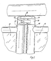
- Fig. 2 shows the upper end of the two door leaves 12 and 11. From this illustration it is clear that a hinge 19 is placed on the upper ends of the vertical frame members 17 and 18 of the two door leaves 12 and 11. Clamping parts 20 and 21 are placed on this hinge 19 in an extension of the central axes of the vertical bars 17 and 18. This is shown particularly clearly in FIGS. 3 to 5.
- the clamping part provided with the reference numeral 21 has two holding tongues 22 which are arranged at a distance from one another and which are equipped with molded-on locking lugs 23 in the region of their free ends.
- the two holding tongues 22 enclose a central web 24 of the other clamping part 20 between them.
- the central web 24 is provided with latching recesses 25, into which the latching lugs 23 of the retaining tongues 22 snap when the folding door 10 is completely closed (FIG. 3) or completely open (FIG. 5).
- the two possible end positions of the folding door 10 are secured by the clamped parts 20 and 21.
- the locking lugs 23 of the holding tongues 22 rest against the central web 24 of the second clamping part 20 when the folding door is only partially open outside the locking recesses 25.
- the latches 23 slide to a certain extent over the central web 20.
- the central web 24 of the clamping part 20 is provided with a longitudinal slot 26 into which a guide web 27 of the clamping part 21 projects.
- Both clamping parts 20 and 21 are designed as flat, one-piece plastic components.
Landscapes
- Health & Medical Sciences (AREA)
- Public Health (AREA)
- Epidemiology (AREA)
- General Health & Medical Sciences (AREA)
- Extensible Doors And Revolving Doors (AREA)
Description
- - Die vorliegende Erfindung betrifft eine Falttür für eine Duschkabine, bestehend aus drei Türflügeln, von denen ein äußerer Türflügel an einem vertikalen Holm anschamiert und andererseits mit dem mittleren Türflügel durch Scharniere gelenkig verbunden ist.
- Eine Falttür für eine Duschkabine der gattungsgemäße Art ist beispielsweise aus der US-A-20 48 909 bekannt.
- Spezielle Maßnahnen, die dazu dienen, die bekannte Falttür in ihrer geschlossenen sowie in ihrer vollständig geöffneten Stellung zu fixieren oder zu sichern, sind der US-A-20 48 909 nicht zu entnehmen.
- Aus der US-A-32 37 239 ist eine Falttür bekannt geworden, bei der eine Fixierung der Falttür sowohl im geschlossenen wie auch im vollständig geöffnetem Zustand möglich ist. Die hierzu vorgeschlagene Konstruktion sieht vor, an den Scharnieren, die im Bereich der oberen und der unteren Enden der im Gelenkbereich liegenden vertikalen Rahmenholme angeschlossen sind, Klemmteile aufzusetzen, welche die vorerwähnte gewünschte Fixierung mit sich bringen. Bei diesen Klemmteilen handelt es sich einerseits um ein die jeweilige Scharnierachse umgebendes Formteil mit zwei abeflachten Seiten sowie um eine Schenkelfeder, deren einer Schenkel von einem Scharnierlappen in der jeweiligen Türflügelebene gehalten und deren anderer Schenkel mit den besagten abgeflachten Seiten des Formteiles kraftschlüssig zusammenwirkt.
- Die Verwendung einer derartigen Konstruktion bei einer Falttür für eine Duschkabine ist aus verschiedenen Gründen heraus ungünstig.
- Einerseits setzt eine derartige Konstruktion die Verwendung von Scharnieren und Klemmteilen voraus, welche auf die gelenkig miteinander verbundenen Türflügel aufgesetzt werden müssen, und zwar in der Ebene des jeweiligen Türblattes. Andererseits stellt der mit dem Formteil kraftschlüssig zusammenwirkende Schenkel der Formreder insofern eine Gefahrenquelle dar, als sich ein Benutzer einer derartigen Falttür an diesem Schenkel verletzen könnte.
- Letztendlich beeinträchtigt die Konstruktion gemäß der US-A-32 37 239 auch das gefällige Aussehen einer derartigen Falttür.
- Aus der US-A-34 18 682 sind Klemmteile für Türflügel bekannt, die formschlüssig miteinander verrasten.
- Hier ist allerdings eine Verrastung nur in der geschlossenen Stellung der Falttür möglich.
- Der vorliegenden Erfindung liegt die Aufgabe zugrunde, eine Falttür der gattungsgemäßen Art mit einer konstruktiv einfachen und funktionell wirksamen Arretierung auszustatten, mittels derer die geschlossene wie auch die vollständig geöffnete Stellung wirksam gesichert ist und welche den äußeren Eindruck der Falttür praktisch nicht negativ beeinträchtigen kann.
- Diese Aufgabe wird erfindungsgemäß dadurch gelöst, daß daß die Scharniere jeweils zwei Scharnierteile aufweisen, die an den Enden benachbarter, vertikaler Flügelrahmenholme festgelegt sind, die Scharnierachse bei völlig geschlossener Falttür gegenüber den beiden Flügelrahmenholmen zu einer Seite nach außen versetzt ist und bei der Bewegung der Falttür in die völlig offene Stellung zu der entgegengesetzten Außenseite der Flügelrahmenholme bewegt wird, und daß am oberen und/oder unteren Ende der Flügelrahmenholme auf einem Zapfen der Scharnierteile jeweils ein Klemmteil drehbar gelagert ist, die Klemmteile in einer Horizontalebene relativ zueinander ständig geführt und sowohl bei völlig geschlossener als auch bei vollständig geöffneter Falltür formschlüssig miteinander verrastet sind.
- Die auf die Rahmenholme aufgesetzten Klemmteile bewirken eine sichere Verrastung sowohl bei geschlossener wie auch bei vollständig geöffneter Falttür und sichern somit die beiden möglichen Endlagen der Falttür. Bedingt durch die Tatsache, daß die Klemmteile an den Enden der Rahmenholme auf diese aufgesetzt sind, wird die Gesamtkonstruktion der Falttür durch die Anbringung einer derartigen Arretierungsseinrichtung nicht beeinträchtigt, unter Umständen besteht sogar die Möglichkeit, vorhandene Falttüren nachträglich mit einer derartigen Arretierungseinrichtung auszustatten.
- Weitere Merkmale der Erfindung sind Gegenstand von abhängigen Ansprüchen.
- In den beigefügten Zeichnungen ist ein Ausführungsbeispiel der Erfindung dargestellt, welches im folgenden näher beschrieben wird.
- Es zeigen :
- Fig. 1 eine Falttür für eine Duschkabine im teilweise geöffneten Zustand,
- Fig. 2 eine Teilansicht der in Fig. 1 mit II bezeichneten Einzelheit bei geschlossener Falttür,
- Fig. 3 eine Ansicht in Richtung des Pfeiles 111 in Fig. 2,
- Fig. 4 eine der Fig. 3 entsprechende Ansicht bei teilweise geöffneter Falttür,
- Fig. 5 eine der Fig. 3 entsprechende Ansicht bei vollständig geöffneter Falttür.
- Die in Fig. 1 dargestellte und insgesamt mit dem Bezugszeichen 10 versehene Falttür für eine Duschkabine weist drei Türflügel 11, 12 und 13 auf. Der mittlere Türflügel 12 ist mit den beiden äußeren Türflügeln 11 und 13 verbunden.
- Der mit dem Bezugszeichen 11 versehene äußere Türflügel ist in bekannter Weise an einem vertikalen Holm 14 anscharniert. Der andere äußere Türflügel 13 ist mit einer Handhabe 15 zur Betätigung der gesamten Falttür 10 ausgestattet. Die beiden Türflügel 12 und 13 sind durch ein Getriebe 16 in bekannter Weise zwangsgekoppelt derart, daß eine Schwenkbewegung des Türflügels 13 winkelgleich auf den mittleren Türflügel 12 übertragen wird.
- Der mittlere Türflügel 12 ist mit dem anderen äußeren Türflügel 11 gelenkig verbunden.
- Fig. 2 zeigt das obere Ende der beiden Türflügel 12 und 11. Aus dieser Darstellung wird deutlich, daß auf die oberen Enden der vertikalen Rahmenholme 17 und 18 der beiden Türflügel 12 und 11 ein Scharnier 19 aufgesetzt ist. Auf dieses Scharnier 19 sind in Verlängerung der Mittelachsen der vertikalen Holme 17 und 18 Klemmteile 20 und 21 aufgesetzt. Dies zeigen die Fig. 3 bis 5 besonders deutlich. Das mit dem Bezugszeichen 21 versehene Klemmteil weist zwei mit Abstand zueinander angeordnete Haltezungen 22 auf, die im Bereich ihrer freien Enden mit angeformten Rastnasen 23 ausgestattet sind.
- Die beiden Haltezungen 22 schließen einen Mittelsteg 24 des anderen Klemmteiles 20 zwischen sich ein. Der Mittelsteg 24 ist mit Rastausnehmungen 25 versehen, in welche die Rastnasen 23 der Haltezungen 22 einrasten, wenn die Falttür 10 vollständig geschlossen (Fig. 3) oder vollständig geöffnet ist (Fig. 5).
- Durch die miteinander verrasteten Klemmteile 20 und 21 werden die beiden möglichen Endlagen der Falttür 10 gesichert.
- Wie die Fig. 4 deutlich macht, liegen die Rastnasen 23 der Haltezungen 22 bei nur teilweise geöffneter Falttür außerhalb der Rastausnehmungen 25 am Mittelsteg 24 des zweiten Klemmteiles 20 an. Die Rastnasen 23 gleiten gewissermaßen über den Mittelsteg 20 hinweg.
- Um diese Längsverschiebung der beiden Klemmteile 21 und 20 relativ zueinander sicher zu führen, ist der Mittelsteg 24 des Klemmteiles 20 mit einem Längsschlitz 26 versehen, in den ein Führungssteg 27 des Klemmteiles 21 hineinragt.
- Beide Klemmteile 20 und 21 sind als flache, einstückige Kunststoffbauteile ausgebildet.
- Abweichend vom dargestellten und beschriebenen Ausführungsbeispiel ist es möglich, das Klemmteil 21 nur mit einer Rastnase an einer Haltezunge 22 auszustatten, ebenso ist es denkbar und möglich, die Arretierungseinrichtung statt am oberen Ende der beiden Türflügel 11 und 12 an deren unterem Ende anzubringen.
- Ebenso besteht die Möglichkeit, an beiden Enden der vertikalen Holme 17 und 18 die erwähnten und beschriebenen Klemmteile 20 und 21 anzubringen.
-
- 10 Falttür
- 11 äußerer Türflügel
- 12 mittlerer Türflügel
- 13 äußerer Türflügel
- 14 vertikaler Holm
- 15 Handhabe
- 16 Getriebe
- 17 Rahmenholm
- 18 Rahmenholm
- 19 Scharnier
- 20 Klemmteil
- 21 Klemmteil
- 22 Haltezunge
- 23 Rastnase
- 24 Mittelsteg
- 25 Rastausnehmung
- 26 Längsschlitz
- 27 Führungssteg
Claims (4)
Priority Applications (1)
| Application Number | Priority Date | Filing Date | Title |
|---|---|---|---|
| AT86103452T ATE44221T1 (de) | 1985-03-15 | 1986-03-14 | Falttuer fuer eine duschkabine (ii). |
Applications Claiming Priority (2)
| Application Number | Priority Date | Filing Date | Title |
|---|---|---|---|
| DE8507608U | 1985-03-15 | ||
| DE8507608U DE8507608U1 (de) | 1985-03-15 | 1985-03-15 | Falttür für eine Duschkabine |
Publications (2)
| Publication Number | Publication Date |
|---|---|
| EP0194699A1 EP0194699A1 (de) | 1986-09-17 |
| EP0194699B1 true EP0194699B1 (de) | 1989-06-28 |
Family
ID=6778674
Family Applications (1)
| Application Number | Title | Priority Date | Filing Date |
|---|---|---|---|
| EP86103452A Expired EP0194699B1 (de) | 1985-03-15 | 1986-03-14 | Falttür für eine Duschkabine (II) |
Country Status (3)
| Country | Link |
|---|---|
| EP (1) | EP0194699B1 (de) |
| AT (1) | ATE44221T1 (de) |
| DE (1) | DE8507608U1 (de) |
Family Cites Families (4)
| Publication number | Priority date | Publication date | Assignee | Title |
|---|---|---|---|---|
| FR707009A (fr) * | 1930-12-04 | 1931-07-02 | Perfectionnements aux portes à plusieurs vantaux | |
| US2048909A (en) * | 1935-09-03 | 1936-07-28 | John A Woodworth | Shower door construction |
| US3237239A (en) * | 1963-08-30 | 1966-03-01 | Rudnick Jack | Hinge structure |
| US3418682A (en) * | 1966-03-28 | 1968-12-31 | Nat Lock Co | Hinge and catch assembly |
-
1985
- 1985-03-15 DE DE8507608U patent/DE8507608U1/de not_active Expired
-
1986
- 1986-03-14 AT AT86103452T patent/ATE44221T1/de not_active IP Right Cessation
- 1986-03-14 EP EP86103452A patent/EP0194699B1/de not_active Expired
Also Published As
| Publication number | Publication date |
|---|---|
| DE8507608U1 (de) | 1985-04-25 |
| EP0194699A1 (de) | 1986-09-17 |
| ATE44221T1 (de) | 1989-07-15 |
Similar Documents
| Publication | Publication Date | Title |
|---|---|---|
| DE3545860C2 (de) | ||
| EP0601286A1 (de) | Tür für ein Kraftfahrzeug | |
| EP0021063A1 (de) | Verstellbarer Faltverschluss für Uhrarmbänder | |
| EP0628691B1 (de) | Dreh-Kipp-Beschlag für Fenster, Türen od.dgl. | |
| EP0176890B1 (de) | Schaltschrank mit einem aus Rahmenschenkeln zusammengesetzten Rahmengestell | |
| EP0383003B1 (de) | Feststellvorrichtung für die Flügel von Festern, Türen od. dgl. | |
| EP0316555B1 (de) | Begrenzungsanschlag für die Öffnungsweite der Flügel von Fenstern, Türen od. dgl. | |
| DE2032517A1 (de) | Rahmengetriebe für Fenster, Türen oder dergleichen | |
| DE3026441C2 (de) | Verstelleinrichtung für Schiebefenster | |
| EP0194699B1 (de) | Falttür für eine Duschkabine (II) | |
| DE2261946A1 (de) | Beschlag fuer aus metall- oder kunststoffprofilen gefertigte fenster und tueren od.dgl | |
| EP0263430A2 (de) | Sonnendach | |
| DE102012111389B4 (de) | Verschlussvorrichtung für Türen mit einem asymmetrischen Türschild | |
| DE3546009A1 (de) | Vorrichtung zur arretierung von kfz-tueren in einer teiloffenen montagestellung | |
| EP0668428A1 (de) | Türanschlag | |
| DE2318408A1 (de) | Schliesstueck mit steg, insbesondere fuer mittelverschluesse an schwenk-kippfenstern | |
| DE2839740A1 (de) | Schiebe-, hebeschiebefenster oder -tuer | |
| EP0240614A2 (de) | Vorrichtung zur Verriegelung einer mittels Scharnieren schwenkbar gehalterten Klappe | |
| EP1060315A1 (de) | Schaltschrank mit einem schrankkorpus und mit gegen-schranktür und schliess-schranktür | |
| DE1962781C2 (de) | Treibstangenverschluß, insbesondere im Falz des Flügels eines Fensters, einer Tür od.dgl. anzuordnendes Kantengetriebe | |
| DE4336203A1 (de) | Schaltschrank mit einem Rahmengestell aus Rahmenschenkeln | |
| EP0006439B1 (de) | Vorrichtung zur Stossstellenüberlappung an Stulpschienen | |
| DE2745934A1 (de) | Ausstellvorrichtung fuer dreh-kipp- fluegel von fenstern, tueren o.dgl. | |
| DE10147990A1 (de) | Schaltschrank | |
| DE8913046U1 (de) | Treibstangen-Beschlag |
Legal Events
| Date | Code | Title | Description |
|---|---|---|---|
| PUAI | Public reference made under article 153(3) epc to a published international application that has entered the european phase |
Free format text: ORIGINAL CODE: 0009012 |
|
| AK | Designated contracting states |
Kind code of ref document: A1 Designated state(s): AT CH FR GB LI |
|
| 17P | Request for examination filed |
Effective date: 19860731 |
|
| 17Q | First examination report despatched |
Effective date: 19870520 |
|
| GRAA | (expected) grant |
Free format text: ORIGINAL CODE: 0009210 |
|
| AK | Designated contracting states |
Kind code of ref document: B1 Designated state(s): AT CH FR GB LI |
|
| REF | Corresponds to: |
Ref document number: 44221 Country of ref document: AT Date of ref document: 19890715 Kind code of ref document: T |
|
| GBT | Gb: translation of ep patent filed (gb section 77(6)(a)/1977) | ||
| ET | Fr: translation filed | ||
| PLBE | No opposition filed within time limit |
Free format text: ORIGINAL CODE: 0009261 |
|
| STAA | Information on the status of an ep patent application or granted ep patent |
Free format text: STATUS: NO OPPOSITION FILED WITHIN TIME LIMIT |
|
| 26N | No opposition filed | ||
| REG | Reference to a national code |
Ref country code: CH Ref legal event code: PUE Owner name: KORALLE SANITAERPRODUKTE GMBH & CO. Ref country code: GB Ref legal event code: 732E |
|
| REG | Reference to a national code |
Ref country code: FR Ref legal event code: TP |
|
| PGFP | Annual fee paid to national office [announced via postgrant information from national office to epo] |
Ref country code: FR Payment date: 19960215 Year of fee payment: 11 |
|
| PGFP | Annual fee paid to national office [announced via postgrant information from national office to epo] |
Ref country code: CH Payment date: 19960219 Year of fee payment: 11 |
|
| PGFP | Annual fee paid to national office [announced via postgrant information from national office to epo] |
Ref country code: GB Payment date: 19960313 Year of fee payment: 11 |
|
| PGFP | Annual fee paid to national office [announced via postgrant information from national office to epo] |
Ref country code: AT Payment date: 19960329 Year of fee payment: 11 |
|
| PG25 | Lapsed in a contracting state [announced via postgrant information from national office to epo] |
Ref country code: GB Effective date: 19970314 Ref country code: AT Effective date: 19970314 |
|
| PG25 | Lapsed in a contracting state [announced via postgrant information from national office to epo] |
Ref country code: LI Effective date: 19970331 Ref country code: CH Effective date: 19970331 |
|
| GBPC | Gb: european patent ceased through non-payment of renewal fee |
Effective date: 19970314 |
|
| REG | Reference to a national code |
Ref country code: CH Ref legal event code: PL |
|
| PG25 | Lapsed in a contracting state [announced via postgrant information from national office to epo] |
Ref country code: FR Free format text: LAPSE BECAUSE OF NON-PAYMENT OF DUE FEES Effective date: 19971128 |
|
| REG | Reference to a national code |
Ref country code: FR Ref legal event code: ST |