EP0194585A2 - Clapet antiretour dans un canal d'injection pour un moule de moussage - Google Patents
Clapet antiretour dans un canal d'injection pour un moule de moussage Download PDFInfo
- Publication number
- EP0194585A2 EP0194585A2 EP86102944A EP86102944A EP0194585A2 EP 0194585 A2 EP0194585 A2 EP 0194585A2 EP 86102944 A EP86102944 A EP 86102944A EP 86102944 A EP86102944 A EP 86102944A EP 0194585 A2 EP0194585 A2 EP 0194585A2
- Authority
- EP
- European Patent Office
- Prior art keywords
- sprue
- bearing beam
- arrangement according
- valve body
- molded part
- Prior art date
- Legal status (The legal status is an assumption and is not a legal conclusion. Google has not performed a legal analysis and makes no representation as to the accuracy of the status listed.)
- Withdrawn
Links
Images
Classifications
-
- B—PERFORMING OPERATIONS; TRANSPORTING
- B29—WORKING OF PLASTICS; WORKING OF SUBSTANCES IN A PLASTIC STATE IN GENERAL
- B29C—SHAPING OR JOINING OF PLASTICS; SHAPING OF MATERIAL IN A PLASTIC STATE, NOT OTHERWISE PROVIDED FOR; AFTER-TREATMENT OF THE SHAPED PRODUCTS, e.g. REPAIRING
- B29C44/00—Shaping by internal pressure generated in the material, e.g. swelling or foaming ; Producing porous or cellular expanded plastics articles
- B29C44/34—Auxiliary operations
- B29C44/58—Moulds
- B29C44/581—Closure devices for pour holes
Definitions
- the invention relates to an arrangement of a check valve in the sprue of a foam mold, in particular a polyurethane foam mold, comprising a valve seat and a disk-shaped valve body made of plastic or rubber-like material.
- a high-precision metal slide is installed in the sprue, which can be moved mechanically or electrically-pneumatically after foaming.
- a slide assembly is in front of the entrance of the sprue, i. H. attached between the foaming unit and the mold; this slide can be opened and closed by the foaming unit or by a direct electrical-pneumatic control.
- a delay in closing the sprue can occur, which can also lead to a deterioration of the molding.
- a so-called quick release is provided on the mold, which carries a locking bolt for the entrance of the sprue and can be brought into the closed or open position in the manner of a pivoting lid, either manually or electropneumatically.
- the closure parts which are usually made of rubber, often have to be replaced. If closures are used for a longer period of time, an exact closure is no longer guaranteed, as a result of which the quality of the moldings is impaired.
- the flow behavior when the foamable mass enters the mold cavity is also impaired if worn valve parts are overflowed.
- the closure can only take place when the entrance of the sprue is so far separated from the foaming unit that the moving closure parts can carry out their movement.
- the foam can emerge from the sprue channel for a more or less long time, as a result of which the quality of the molding is adversely affected and, at the same time, the closure parts are constantly contaminated.
- simple closure parts are placed in the sprue. It is a matter of Parts that are used only once or only a few times.
- the shape of the valve body ranges from round, simple plastic discs to plug shapes and valve balls.
- valve bodies are unusable after each foaming process because they are at least partially enclosed by a plyuretan skin that can hardly be removed.
- the invention has for its object to design an arrangement of the type mentioned in such a way that an exact and exactly reproducible closure of the sprue channel is possible that the closure occurs immediately after the foaming process, that the manufacture of the check valve is simple and inexpensive and that there is no need for cleaning and yet multiple use is possible. Furthermore, the check valve is to be used in a wide variety of, e.g. B. milled and cast forms and regardless of the respective mold structure and the shape of the mold nest.
- the disk-shaped valve body is made in one piece with a bearing beam which, with a bearing surface remote from the valve body, tightly crosses a sprue channel boundary surface of the first of two shaped parts defining the sprue channel, so that the over the cross section of the sprue protruding portions of the bearing beam between the form-fitting surfaces of the two molded parts are clamped and that the valve seat is attached to a shoulder of a channel-shaped runner boundary surface of the second molded part.
- the disk-shaped valve body with the bearing beam is easy to manufacture, for. B. in the injection molding process.
- the manufacturing costs are correspondingly low.
- the installation of the element consisting of valve body and bearing beam is extremely simple. When removing the molding, the valve body is often removed as well. It may then still be slightly related, either to the molded product and / or to the foam plug formed in the outer part of the sprue. As a rule, however, it is easy to remove from the molding or the outer foam plug, since if the plastic is chosen appropriately for the manufacture of the valve body and, if appropriate, coated with non-stick materials, it adheres only with little adhesive force. Foaming around the valve body does not occur, so that any foam residues can be easily peeled off.
- the operator takes the closure part in hand for inspection and then reinserts it into the sprue before the molded parts come together. This takes place in a matter of seconds and does not significantly reduce the machine's performance. Due to the use of materials for the valve body, which resist a connection and adhesion with PUR foam and at the same time have sufficient flexibility and low material fatigue value, it is frequently reused achievable. Since the valve is based on the non-return principle, the earliest possible closure of the sprue is ensured, so that there is no fear of foam reflux from the mold cavity and the quality of the molding and material consumption are optimized.
- the position of the check valve in the sprue channel is moved as close as possible to the attachment point of the foaming unit in order to keep the volume of loss corresponding to the volume of the sprue channel between the check valve and the mouthpiece of the foaming unit to a minimum.
- the length of the section of the sprue channel located between the check valve and the mold cavity will also be kept as short as possible to avoid foam losses, although consideration must be given to the shape of the sprue channel cross section that may be necessary to adapt to the shape of the mold cavity at the junction with the mold cavity. In view of this, occasionally certain minimum lengths of the sprue section between the check valve and the mold cavity are necessary in order to achieve the transition from the valve cross-section to the desired mouth cross-section while observing the rheological requirements. (Claim 1)
- the sprue channel boundary surface crossed by the bearing beam and the form-fitting surface associated with the first molded part be formed by a common plane surface and that in the form-fitting surface the second molded part recesses are formed for receiving the protruding portions of the bearing beam. It is also possible to use the recesses for receiving the protruding sections trained so that they form a kind of snap connection with the protruding portions of the bearing beam. Then it is ensured that the valve body remains in place when removing the molded article and the foam plug located between the valve and the foaming unit and must be removed by a targeted removal action. (Claim 2)
- the bearing beam can be designed with a semicircular cross section, the recesses in the second molded part for receiving the projecting sections then correspondingly having a semicircular cross section.
- other cross-sectional shapes are also possible for the bearing beam. It is essential that the bearing beam is rigid enough to bear in its section within the sprue with sufficient sealing pressure on the sprue boundary surface of the first molded part. (Claim 3)
- the end sections of the bearing beam have a cross-sectional oversize compared to the cross-section of the recesses, such that an elastic squeeze of the protrusions occurs within the recesses when there is a positive fit. (Claim 4)
- valve seat and the valve seat contact surface of the valve body are flat and essentially perpendicular to the flow direction of the sprue. (Claim 5)
- the deflection limit stop can be attached to the first molded part within the sprue channel. (Claim 8)
- the cross section of the sprue channel downstream of the valve seat be expanded in such a way that there is no significant narrowing of the flow cross section of the sprue channel through the disk-shaped valve body when it is in the open position .
- the channel expansion is preferably formed by a depression in the bottom of the channel-shaped sprue channel boundary surface belonging to the second molded part.
- the bearing beam be provided with positioning projections for engaging in receiving holes of at least one of the form-fitting surfaces.
- the cantilever Both protruding sections each have a preferably slightly conical pin for engagement in corresponding receiving holes in the form-fitting surface of the second molded part.
- the conical pins By pressing the conical pins into the receiving holes, a seat can be ensured which ensures that the bearing beam is held until the valve body with the bearing beam is intentionally removed.
- the bearing beam can also have a preferably square pin on each of the two projecting sections for engaging in corresponding receiving holes in the form-fitting surface of the first molded part. This results in additional centering on the form-fitting surface of the first molded part.
- these square pins can be ejector attachment points when manufactured on an automatic injection molding machine. (Claim 13)
- the dimensions of the closure body together with the bearing bar are generally so small that it is advisable to attach a handle element which facilitates handling to the bearing bar and a receiving chamber for this handle element in one of the form-fitting surfaces.
- a production-technically and rheologically advantageous embodiment results when the trough-shaped sprue boundary surface of the second molded part is approximately semicircular in cross-section and the disk-shaped valve body accordingly has an approximately semicircular outline.
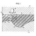
- the sprue 20 is composed of a section 20a and a section 20b.
- the section 20a extends from a coupling surface 22, in which the mouthpiece of a foaming unit is connected, to a shoulder 24, which is essentially perpendicular to the longitudinal direction of the sprue 20.
- the section 20b of the sprue extends from the shoulder 24 to the junction of the sprue in a mold cavity, not shown, which is formed between the mold parts 10 and 12 and in which the molding is to be formed, for example a shoe sole.
- a check valve is formed at the location of the shoulder 24.
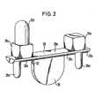
- This check valve comprises a valve body 26 which is made in one piece with a bearing beam 28 (see FIG. 2).
- the bearing beam has a semicircular cross-section and rests with its contact surface 28a on the form-fitting surface 14 of the first molded part 10 (ie the sprue channel boundary surface of the first molded part 10).
- the bearing beam 28 has two projecting sections 28b which project beyond the width of the channel 18 and are received by semi-cylindrical recesses 30 in the form-fitting surface 16 of the second molded part 12.
- the valve body 26 is 1 on its left side in FIG. 1 and lies against the likewise flat shoulder surface 24, which forms a valve seat.
- the sections 28b are slightly oversized relative to the recesses 30, so that they are elastically squeezed between the recesses 30 and the form-fitting surface 14 of the first molded part 10 during the form-fit connection.
- Conical pins 28d extend slightly from the semi-cylindrical lateral surface 28c of the bearing beam 28 and are received by holes (not shown) in the form-fitting surface 16 of the second molded part 12.
- Cuboid pins 28e extend from the contact surface of the bearing beam 28 and are received in the form-fitting surface 14 of the first molded part 10 by receiving holes (also not shown). On one of the cubic pins 28e there is a grip element 28f, on which the fingers can grip when the bearing beam 28 is inserted into the second molded part 12. Between the valve body 26 and the bearing beam 28, a weakening groove 32 is provided, so that the valve body 26 can be pivoted from the closed position shown in FIG. The open position of the valve body 24 is defined by a stop pin 34, which is anchored within the sprue 20 in the form-fitting surface 14.
- a foaming unit (not shown) is placed at 22. Then the foamable reaction mixture begins to be introduced through the sprue 20 into the mold cavity under slight pressure. The valve body 26 inevitably opens, so that the reaction mixture can flow past the valve body into the mold cavity.
- a channel widening 18a is provided in the bottom of the channel-shaped channel delimitation surface 18 next to the shoulder surface 24 (valve seat).
- the cross section of the trough 18 is semicircular in the region of the section 20a, while in the region of the section 20b the trough is composed of a rectangular cross section and a semicircular cross section.
- the pressure which arises in the mold cavity as a result of the foaming reaction causes the disk-shaped valve body 26 to close.
- the mold parts 10 and 12 are lifted off one another and the resulting molding is removed. If the beam 28 is loosely inserted into the molded part 12, the valve body 26 can often be removed with the resulting molding, the valve body 26 may adhere to the runner plug created to the right and left of it or to one of the two. Thanks to a suitable choice of material for the valve body 26 or a corresponding surface coating, however, the respective foam plug can be easily detached from the valve body 26.
- valve body 26 can be checked and, if necessary, cleaned or replaced after each foaming process or, if necessary, after several.
Landscapes
- Moulds For Moulding Plastics Or The Like (AREA)
Applications Claiming Priority (2)
| Application Number | Priority Date | Filing Date | Title |
|---|---|---|---|
| DE19853507954 DE3507954C1 (de) | 1985-03-06 | 1985-03-06 | Anordnung eines Rueckschlagventils im Angusskanal einer Schaeumform |
| DE3507954 | 1985-03-06 |
Publications (2)
| Publication Number | Publication Date |
|---|---|
| EP0194585A2 true EP0194585A2 (fr) | 1986-09-17 |
| EP0194585A3 EP0194585A3 (fr) | 1989-01-25 |
Family
ID=6264388
Family Applications (1)
| Application Number | Title | Priority Date | Filing Date |
|---|---|---|---|
| EP86102944A Withdrawn EP0194585A3 (fr) | 1985-03-06 | 1986-03-06 | Clapet antiretour dans un canal d'injection pour un moule de moussage |
Country Status (2)
| Country | Link |
|---|---|
| EP (1) | EP0194585A3 (fr) |
| DE (1) | DE3507954C1 (fr) |
Cited By (1)
| Publication number | Priority date | Publication date | Assignee | Title |
|---|---|---|---|---|
| WO1999064800A1 (fr) * | 1998-06-10 | 1999-12-16 | BSH Bosch und Siemens Hausgeräte GmbH | Corps thermo-isolant, en particulier pour appareils menagers |
Citations (3)
| Publication number | Priority date | Publication date | Assignee | Title |
|---|---|---|---|---|
| GB1060658A (en) * | 1962-11-22 | 1967-03-08 | Angus George Co Ltd | Improvements in and relating to moulds for plastic materials |
| DE1948455A1 (de) * | 1969-09-25 | 1971-04-08 | Bayer Ag | Form fuer die Herstellung von Formteilen aus reaktionsfaehigen chemischen Komponenten |
| US3814124A (en) * | 1972-09-20 | 1974-06-04 | Exxon Research Engineering Co | Thermoplastic check valve |
-
1985
- 1985-03-06 DE DE19853507954 patent/DE3507954C1/de not_active Expired
-
1986
- 1986-03-06 EP EP86102944A patent/EP0194585A3/fr not_active Withdrawn
Patent Citations (3)
| Publication number | Priority date | Publication date | Assignee | Title |
|---|---|---|---|---|
| GB1060658A (en) * | 1962-11-22 | 1967-03-08 | Angus George Co Ltd | Improvements in and relating to moulds for plastic materials |
| DE1948455A1 (de) * | 1969-09-25 | 1971-04-08 | Bayer Ag | Form fuer die Herstellung von Formteilen aus reaktionsfaehigen chemischen Komponenten |
| US3814124A (en) * | 1972-09-20 | 1974-06-04 | Exxon Research Engineering Co | Thermoplastic check valve |
Cited By (1)
| Publication number | Priority date | Publication date | Assignee | Title |
|---|---|---|---|---|
| WO1999064800A1 (fr) * | 1998-06-10 | 1999-12-16 | BSH Bosch und Siemens Hausgeräte GmbH | Corps thermo-isolant, en particulier pour appareils menagers |
Also Published As
| Publication number | Publication date |
|---|---|
| EP0194585A3 (fr) | 1989-01-25 |
| DE3507954C1 (de) | 1986-08-07 |
Similar Documents
| Publication | Publication Date | Title |
|---|---|---|
| DE69128049T2 (de) | Verfahren zum Einspritzgiessen von Rasierklingeneinheiten und Einheiten hergestellt durch ein solches Verfahren | |
| DE3526632C2 (fr) | ||
| DE3532424A1 (de) | Verfahren und vorrichtung zum aufformen einer eingespritzten einfassung mit genauen abmessungen auf den umfang eines ebenen oder gewoelbten teils mit abmessungstoleranzen und danach hergestelltes zusammengesetztes produkt | |
| DE4041330A1 (de) | Abnehmbarer einsatz fuer giessformen und giessform zum herstellen von formteilen | |
| EP0671249A1 (fr) | Procédé et dispositif pour la fabrication de lentilles optiques | |
| AT512318B1 (de) | Verfahren zur herstellung von spritzgussteilen und vorrichtung zur durchführung dieses verfahrens | |
| DE3621870A1 (de) | Rohrverbindung | |
| EP0194585A2 (fr) | Clapet antiretour dans un canal d'injection pour un moule de moussage | |
| DE102005006794A1 (de) | Mehrfachkomponenten-Spritzverfahren zur Bildung eines aus mehreren Komponenten bestehenden Körpers | |
| EP0175691A1 (fr) | Plaque de revetement pour la chambre de moulage d'une machine a mouler | |
| DE3711079A1 (de) | Verfahren und vorrichtung zum spritzgiessen von formteilen aus mindestens zwei verschiedenen kunststoffkomponenten | |
| DE69505431T2 (de) | Form für Einsatzstücke und Herstellungsverfahren unter Verwendung von dieser Form | |
| DE102020107547B4 (de) | Verfahren zum Gießen, vorzugsweise zum Spritzgießen, eines Fahrzeugbauteils mit verbesserter Abdichtung der Gießform sowie Gießform | |
| EP0313916B1 (fr) | Appareil pour produire des objets en un mélange réactif coulant, consistant en composantes réactives coulantes et réagissant pour former une matière plastique, notamment une matière plastique moussée | |
| DE102013018968A1 (de) | Spritzgießwerkzeug | |
| DE1134823B (de) | Spritzgiessform fuer thermoplastische Kunststoffe verarbeitende Spritzgiessmaschinen | |
| DE3734118C2 (fr) | ||
| DE10255993B4 (de) | Spritzgießwerkzeug und zugehöriges Verfahren | |
| EP1338398A1 (fr) | Dispositif pour le moulage à plusieurs composants d'objets en matière plastique | |
| DE3821060C2 (fr) | ||
| DE4234326A1 (de) | Vorrichtung zum Spritzformen von Batteriekästen | |
| DE202005011955U1 (de) | Rastclip | |
| DE69020274T2 (de) | Vorrichtung zur Befestigung von Gleitscheiben an einem Absperrschieber. | |
| DE3601403C1 (en) | Valve | |
| DE102019135641A1 (de) | Vorrichtung und Verfahren zur Herstellung von Kunststoffbauteilen |
Legal Events
| Date | Code | Title | Description |
|---|---|---|---|
| PUAI | Public reference made under article 153(3) epc to a published international application that has entered the european phase |
Free format text: ORIGINAL CODE: 0009012 |
|
| AK | Designated contracting states |
Kind code of ref document: A2 Designated state(s): DE FR GB IT |
|
| ITCL | It: translation for ep claims filed |
Representative=s name: JACOBACCI CASETTA & PERANI S.P.A. |
|
| EL | Fr: translation of claims filed | ||
| PUAL | Search report despatched |
Free format text: ORIGINAL CODE: 0009013 |
|
| AK | Designated contracting states |
Kind code of ref document: A3 Designated state(s): DE FR GB IT |
|
| STAA | Information on the status of an ep patent application or granted ep patent |
Free format text: STATUS: THE APPLICATION IS DEEMED TO BE WITHDRAWN |
|
| 18D | Application deemed to be withdrawn |
Effective date: 19890726 |
|
| RIN1 | Information on inventor provided before grant (corrected) |
Inventor name: SCHWEIKERT, SIEGFRIED |