EP0194474B1 - Method for regulating cavitation - Google Patents
Method for regulating cavitation Download PDFInfo
- Publication number
- EP0194474B1 EP0194474B1 EP86102057A EP86102057A EP0194474B1 EP 0194474 B1 EP0194474 B1 EP 0194474B1 EP 86102057 A EP86102057 A EP 86102057A EP 86102057 A EP86102057 A EP 86102057A EP 0194474 B1 EP0194474 B1 EP 0194474B1
- Authority
- EP
- European Patent Office
- Prior art keywords
- cavitation
- measured
- pumping plant
- pump
- microprocessor
- Prior art date
- Legal status (The legal status is an assumption and is not a legal conclusion. Google has not performed a legal analysis and makes no representation as to the accuracy of the status listed.)
- Revoked
Links
Images
Classifications
-
- F—MECHANICAL ENGINEERING; LIGHTING; HEATING; WEAPONS; BLASTING
- F17—STORING OR DISTRIBUTING GASES OR LIQUIDS
- F17D—PIPE-LINE SYSTEMS; PIPE-LINES
- F17D1/00—Pipe-line systems
- F17D1/20—Arrangements or systems of devices for influencing or altering dynamic characteristics of the systems, e.g. for damping pulsations caused by opening or closing of valves
-
- F—MECHANICAL ENGINEERING; LIGHTING; HEATING; WEAPONS; BLASTING
- F04—POSITIVE - DISPLACEMENT MACHINES FOR LIQUIDS; PUMPS FOR LIQUIDS OR ELASTIC FLUIDS
- F04B—POSITIVE-DISPLACEMENT MACHINES FOR LIQUIDS; PUMPS
- F04B11/00—Equalisation of pulses, e.g. by use of air vessels; Counteracting cavitation
-
- F—MECHANICAL ENGINEERING; LIGHTING; HEATING; WEAPONS; BLASTING
- F04—POSITIVE - DISPLACEMENT MACHINES FOR LIQUIDS; PUMPS FOR LIQUIDS OR ELASTIC FLUIDS
- F04D—NON-POSITIVE-DISPLACEMENT PUMPS
- F04D15/00—Control, e.g. regulation, of pumps, pumping installations or systems
- F04D15/0066—Control, e.g. regulation, of pumps, pumping installations or systems by changing the speed, e.g. of the driving engine
-
- F—MECHANICAL ENGINEERING; LIGHTING; HEATING; WEAPONS; BLASTING
- F04—POSITIVE - DISPLACEMENT MACHINES FOR LIQUIDS; PUMPS FOR LIQUIDS OR ELASTIC FLUIDS
- F04D—NON-POSITIVE-DISPLACEMENT PUMPS
- F04D29/00—Details, component parts, or accessories
- F04D29/66—Combating cavitation, whirls, noise, vibration or the like; Balancing
- F04D29/669—Combating cavitation, whirls, noise, vibration or the like; Balancing especially adapted for liquid pumps
-
- F—MECHANICAL ENGINEERING; LIGHTING; HEATING; WEAPONS; BLASTING
- F17—STORING OR DISTRIBUTING GASES OR LIQUIDS
- F17D—PIPE-LINE SYSTEMS; PIPE-LINES
- F17D1/00—Pipe-line systems
- F17D1/02—Pipe-line systems for gases or vapours
- F17D1/065—Arrangements for producing propulsion of gases or vapours
- F17D1/07—Arrangements for producing propulsion of gases or vapours by compression
Definitions
- the invention relates to a method for regulating conveying units for the transport of liquids and / or gases in pipelines according to the preamble of claim 1.
- Conveyor units are generally used in connection with pipelines for transport or conveying, centrifugal pumps, displacement pumps or water ring pumps (vacuum pumps) being mentioned.
- cavitation describes a phenomenon that occurs when the Pressure in a liquid, for example due to excessive speed, drops in some places to the evaporation pressure. The resulting steam bubbles collapse again at higher pressure, and the "blows" associated with this lead to considerable stress on the delivery unit and the pipelines.
- German laid-open specification DE-A-32 36 815 has also made a monitoring and control device on pipelines for transporting liquids to suppress cavitation known. So far, we have limited our to measuring physical quantities such as temperature or liquid level, It is proposed there to measure the cavitation directly by means of a pressure transducer in the form of a measuring membrane with foil strain gauges. Using a microprocessor that processes the measured cavitation values, the speed of a centrifugal pump can be changed until an optimal operating state occurs without any cavitation.
- the invention takes the novel way of deliberately maintaining a certain minimal residual cavitation. So far - although inadequate - care has been taken to eliminate the cavitation as completely as possible, the invention therefore surprisingly provides for the measure to allow a minimal, however controllable, residual cavitation.
- This unprecedented procedural step is based on the consideration of maintaining the inherently harmful disturbance variable "cavitation" to a small extent during operation, so that the disturbance variable remains under control at all times, so to speak.
- the residual cavitation can easily be chosen so low that there are no fear of harmful side effects on the delivery unit and on the pipelines. It is sufficient if the residual cavitation is just barely measurable.
- An important advantage of the invention is that the envisaged ongoing detection or measurement of the cavitation allows the delivery unit to be switched off if the measured cavitation is harmful and can be predetermined Cavitation limit exceeded. Basically, a completely self-regulating system is created, in which the flow rates are adjusted in accordance with the different operating conditions so that manual monitoring can be omitted. If a critical limit is exceeded, the corresponding system can be switched off automatically.
- the "self-regulation" takes place in that, depending on the measured cavitation, the speed of a pump used as a delivery unit is regulated accordingly.
- the invention can also be used in such a way that the measured cavitation is used to influence, for example, a throttle valve - and thus the delivery rate.
- the invention can also be used in water ring pumps.
- the fresh water supply was increased or additional ballast gas or air was provided to counteract the harmful cavitation that had occurred.
- the fresh water consumption can now be reduced and also not only restrict the use of ballast gas or air, but even avoid the latter completely, since the pump speed can be reduced until the capacity of the pump matches the gas / air volume and the cavitation is acceptable.
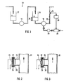
- a multi-stage evaporation plant 10 is shown schematically in FIG. 1.
- the liquid accumulated in a first stage into a liquid container 12 is conveyed into a liquid container 14 of a further stage by means of a centrifugal pump 16. There the liquid has a liquid level (level) 20.
- the liquid is further conveyed through a pipeline 22 by means of a centrifugal pump 18.
- a centrifugal pump 18 On the pressure side of the centrifugal pump 18 or the pipeline 22, the cavitation is now measured at a pipe branch 24.
- the measured values are fed to a microprocessor 26 which, via a frequency converter 28, influences an electric motor 30 for adjusting the speed of the centrifugal pump 18.
- the The speed of the centrifugal pump 18 is controlled in such a way that a minimal residual cavitation is maintained (which will be explained in more detail below with reference to FIGS. 4 and 5).
- the pipe branch 24 contains a measuring membrane 32 with glued-on foil strain gauges 34.
- flexible seals 36 are provided in the area of a flange 38, which act as a support for the flexible seals 36 serves.
- a clamping device which is necessary per se, for bracing the flexible seals 36, the measuring membrane 32, is not shown in FIGS. 2 and 3.
- Fig. 3 shows a further embodiment, wherein the measuring membrane 32 is arched to ensure the required mechanical resistance both in vacuum and in overpressure.
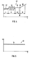
- Cavitation 42 is present in the area marked I, while area II indicates a pulsation 44.
- the area "III” represents the normal operation 46, which is again specified separately within the area IV as the condition referred to in the above-mentioned German laid-open specification 32 36 815 as the optimal operating condition 48.
- the area V represents a filling curve 50, i.e. a state is shown as it occurs when the suction side of the centrifugal pump 18 in FIG. 1 is filled after an insufficient change in the speed when the liquid level 20 of the liquid container 14 rises.
- the diagram 52 in FIG. 5 shows the operating state realized with the invention, in which a minimal residual cavitation 54 is deliberately maintained, and this deviates from the operating state 48 shown in area IV in FIG. 4.
- the associated low level 20 ensures a relatively short dead time or dwell time of the liquid.
- Another significant advantage of the invention is given in conveyor units, the speed of which can be changed. Since the possibility of measuring the cavitation is provided, a cavitation limit value can easily be set at which the system is switched off or an alarm is given.
- the invention advantageously allows a considerable restriction of fresh water consumption and the use of ballast gas or air, since the pump speed in the method according to the invention is regulated down until the capacity of the pump matches the gas / air volume and the cavitation is depressed to the remaining cavitation 54.
Landscapes
- Engineering & Computer Science (AREA)
- Mechanical Engineering (AREA)
- General Engineering & Computer Science (AREA)
- Chemical & Material Sciences (AREA)
- Combustion & Propulsion (AREA)
- Structures Of Non-Positive Displacement Pumps (AREA)
- Reciprocating Pumps (AREA)
- Physical Or Chemical Processes And Apparatus (AREA)
- Details Of Valves (AREA)
- Control Of Conveyors (AREA)
- Control Of Positive-Displacement Pumps (AREA)
- Hydraulic Turbines (AREA)
- Control Of Non-Electrical Variables (AREA)
Abstract
Description
Die Erfindung betrifft ein Verfahren zur Regelung von Förderaggregaten für den Transport von Flüssigkeiten und/oder Gasen in Rohrleitungen gemäß dem Oberbegriff des Anspruchs 1.The invention relates to a method for regulating conveying units for the transport of liquids and / or gases in pipelines according to the preamble of
In vielen Bereichen der Technik kommt der Förderung von Flüssigkeiten und/oder Gasen eine große Bedeutung zu, und als ein Beispiel seien hier die Eindampfanlagen im Bereich der Molkereiwirtschaft genannt.In many areas of technology, the conveyance of liquids and / or gases is of great importance, and one example is the evaporation plants in the field of dairy industry.
Für den Transport bzw. für die Förderung werden allgemein Förderaggregate in Verbindung mit Rohrleitungen eingesetzt, wobei etwa Zentrifugalpumpen, Verdrängerpumpen oder auch Wasserringpumpen (Vakuumpumpen) zu nennen sind.Conveyor units are generally used in connection with pipelines for transport or conveying, centrifugal pumps, displacement pumps or water ring pumps (vacuum pumps) being mentioned.
Grundsätzlich bereitet der Transport von Flüssigkeiten zwar keine technischen Schwierigkeiten, allerdings mit Ausnahme der bekannten Kavitation, deren schädliche Einwirkungen auf das jeweilige Förderaggregat und auch auf die Rohrleitungen immer noch ein gravierendes Problem darstellen.Basically, the transportation of liquids does not pose any technical difficulties, but with the exception of the known cavitation, the harmful effects of which on the respective delivery unit and also on the pipelines still represent a serious problem.
Der Begriff Kavitation (Hohlsogbildung, Hohlraumbildung) beschreibt eine Erscheinung, die dann auftritt, wenn der Druck in einer Flüssigkeit z.B. infolge zu großer Geschwindigkeit an einigen Stellen auf den Verdampfungsdruck absinkt. Die dabei entstehenden Dampfblasen stürzen bei höherem Druck wieder zusammen, und die damit verbundenen "Schläge" führen zu erheblichen Beanspruchungen des Förderaggregates und der Rohrleitungen.The term cavitation describes a phenomenon that occurs when the Pressure in a liquid, for example due to excessive speed, drops in some places to the evaporation pressure. The resulting steam bubbles collapse again at higher pressure, and the "blows" associated with this lead to considerable stress on the delivery unit and the pipelines.
Es können sich also - insbesondere bei Flüssigkeiten, deren Betriebstemperaturen nahe am Siedepunkt liegen - bei Unterschreitung des Siededruckes Dampfblasen bilden. Nach der durch das Förderaggregat hervorgerufenen Druckerhöhung wird der Siededruck wieder überschritten, die Dampfblasen fallen zusammen, und es tritt die schädliche Kavitation ein (vgl. KSB "Kreiselpumpenlexikon" 2. Auflage, Seite 121 - 122 und Fuchslocher/Schulz "Die Pumpen", Springer Verlag 1965, Seite 100 - 109).So vapor bubbles can form - especially with liquids whose operating temperatures are close to the boiling point - when the boiling pressure is not reached. After the pressure increase caused by the delivery unit, the boiling pressure is exceeded again, the vapor bubbles collapse, and harmful cavitation occurs (cf. KSB "Centrifugal Pump Encyclopedia" 2nd edition, pages 121 - 122 and Fuchslocher / Schulz "Die Pumpen", Springer Verlag 1965, pages 100-109).
In der Praxis macht sich die Kavitation durch ein Ansteigen des Geräuschpegels sowie durch einen unruhigen Lauf des Förderaggregates bemerkbar. Dabei kann auch ein sogenanntes pulsierendes Arbeiten auftreten. Einhergehend damit werden die Förderbedingungen erheblich verschlechtert, so daß der Wirkungsgrad des Förderaggregates absinkt. Schließlich kann die Kavitation sogar zur Materialzerstörung führen (vgl. die voranstehend genannten Literaturstellen).In practice, the cavitation is noticeable by an increase in the noise level and an uneven running of the delivery unit. So-called pulsating work can also occur. Along with this, the funding conditions deteriorate considerably, so that the efficiency of the conveyor unit drops. Finally, cavitation can even lead to material destruction (see the references mentioned above).
Um den geschilderten schädlichen Wirkungen der Kavitation zu begegnen, hat man sich bisher in der Praxis meistens damit beholfen, bestimmte Meßgrößen, wie die Temperatur der Flüssigkeit oder das Niveau bzw. die Zulaufhöhe zu kontrollieren und in Abhängigkeit dieser Größe eine manuelle Einstellung des Förderaggregates vorzunehmen. Es ist ohne weiteres ersichtlich, daß ein solches Verfahren sehr aufwendig ist und zudem auch unter der Gefahr einer Ungenauigkeit leidet.In order to counter the described harmful effects of cavitation, it has so far mostly been used in practice to control certain measured variables, such as the temperature of the liquid or the level or the inlet height, and to make a manual adjustment of the delivery unit depending on this size. It is readily apparent that such a method is very complex and also suffers from the danger of inaccuracy.
Da sich die Kavitation unter anderem durch Erhöhung des Geräuschpegels äußert, sind auch schon Meßeinrichtungen mittels eines Mikrofones bekannt geworden (Brüel & Kjaer "Technical Review" No. 4 - 1980). Jedoch ist diese Meßmethode nicht zuverlässig genug und außerdem auch zu störempfindlich.Since the cavitation manifests itself among other things by increasing the noise level, measuring devices using a microphone have also become known (Brüel & Kjaer "Technical Review" No. 4 - 1980). However, this method of measurement is not reliable enough and is also too sensitive to interference.
Durch die deutsche Offenlegungsschrift DE-A-32 36 815 ist auch schon eine Überwachungs- und Kontrolleinrichtung an Rohrleitungen zum Transport von Flüssigkeiten zur Unterdrückung von Kavitation bekannt geworden. Während man sich bisher darauf beschränkt hat, physikalische Größen wie die Temperatur oder das Flüssigkeitsniveau zu messen, wird dort vorgeschlagen, mittels eines Druckaufnehmers in Form einer Meßmembran mit Foliendehnungsmeßstreifen die Kavitation direkt zu messen. Unter Verwendung eines Mikroprozessors, der die gemessenen Kavitationswerte verarbeitet, läßt sich die Drehzahl einer Zentrifugalpumpe verändern, bis ein optimaler Betriebszustand ohne jegliche Kavitation eintritt.The German laid-open specification DE-A-32 36 815 has also made a monitoring and control device on pipelines for transporting liquids to suppress cavitation known. So far, we have limited ourselves to measuring physical quantities such as temperature or liquid level, It is proposed there to measure the cavitation directly by means of a pressure transducer in the form of a measuring membrane with foil strain gauges. Using a microprocessor that processes the measured cavitation values, the speed of a centrifugal pump can be changed until an optimal operating state occurs without any cavitation.
Durch die bekannte Überwachungs- und Kontrolleinrichtung gemäß der deutschen Offenlegungsschrift DE-A-32 36 815 wird zwar gegenüber dem bisherigen manuellen Verfahren ein bedeutsamer Fortschritt erzielt, allerdings kann auch dieses Verfahren in der Praxis noch nicht vollständig überzeugen.The well-known monitoring and control device according to German published patent application DE-A-32 36 815, although significant progress has been achieved compared to the previous manual method, this method, however, cannot yet be completely convincing in practice.
Hier greift nun die Erfindung ein, der die Aufgabe zugrunde liegt, ein Verfahren zur Regelung von Förderaggregaten für den Transport von Flüssigkeiten und/oder Gasen in Rohrleitungen zu schaffen, welches die schädlichen Wirkungen der Kavitation weitgehend ausschaltet.This is where the invention intervenes, which is based on the object of creating a method for regulating delivery units for the transport of liquids and / or gases in pipelines, which largely eliminates the harmful effects of cavitation.
Die Lösung dieser Aufgabe erfolgt bei dem im Oberbegriff des Anspruchs 1 genannten Verfahren dadurch, daß das Förderaggregat in Abhängigkeit von der gemessenen Kavitation so eingestellt wird, daß eine minimale Restkavitation verbleibt.This object is achieved in the method mentioned in the preamble of
Die Erfindung beschreitet den neuartigen Weg, ganz bewußt eine gewisse minimale Restkavitation beizubehalten. Während man bisher - wenn auch in unzulänglicher Weise - darauf bedacht gewesen ist, die Kavitation möglichst vollständig zu beseitigen, sieht die Erfindung also überraschend die Maßnahme vor, eine - allerdings kontrollierbare - minimale Restkavitation durchaus zuzulassen.The invention takes the novel way of deliberately maintaining a certain minimal residual cavitation. So far - although inadequate - care has been taken to eliminate the cavitation as completely as possible, the invention therefore surprisingly provides for the measure to allow a minimal, however controllable, residual cavitation.
Diesem verblüffenden Verfahrensschritt liegt die Überlegung zugrunde, die an sich schädliche Störgröße "Kavitation" während des Betriebes in geringem Maße beizubehalten, damit die Störgröße sozusagen jederzeit unter Kontrolle bleibt. Die Restkavitation kann ohne weiteres so gering gewählt werden, daß schädliche Nebenwirkungen auf das Förderaggregat und auf die Rohrleitungen nicht zu befürchten sind. Es genügt, wenn die Restkavitation meßtechnisch gerade noch erfaßbar ist.This astounding procedural step is based on the consideration of maintaining the inherently harmful disturbance variable "cavitation" to a small extent during operation, so that the disturbance variable remains under control at all times, so to speak. The residual cavitation can easily be chosen so low that there are no fear of harmful side effects on the delivery unit and on the pipelines. It is sufficient if the residual cavitation is just barely measurable.
Ein bedeutsamer Vorteil der Erfindung besteht darin, daß die vorgesehene laufende Erfassung bzw. Messung der Kavitation es erlaubt, das Förderaggregat abzuschalten , wenn die gemessene Kavitation einen schädlichen und vorgebbaren Kavitationsgrenzwert überschreitet. Es wird also im Grunde ein sich vollständig selbst regulierendes System geschaffen, bei welchem die Fördermengen in Anpassung an die unterschiedlichen Betriebsbedingungen so geregelt werden, daß eine manuelle Überwachung entfallen kann. Bei Überschreiten eines kritischen Grenzwertes kann die entsprechende Anlage selbstätig abgeschaltet werden.An important advantage of the invention is that the envisaged ongoing detection or measurement of the cavitation allows the delivery unit to be switched off if the measured cavitation is harmful and can be predetermined Cavitation limit exceeded. Basically, a completely self-regulating system is created, in which the flow rates are adjusted in accordance with the different operating conditions so that manual monitoring can be omitted. If a critical limit is exceeded, the corresponding system can be switched off automatically.
In zweckmäßiger Ausgestaltung der Erfindung erfolgt die "Selbstregulierung" dadurch, daß in Abhängigkeit der gemessenen Kavitation die Drehzahl einer als Förderaggregat eingesetzten Pumpe entsprechend geregelt wird. Die Erfindung läßt sich aber auch ebenso dahingehend einsetzen, daß die gemessene Kavitation herangezogen wird, um etwa ein Drosselventil - und damit die Fördermenge - zu beeinflussen.In an expedient embodiment of the invention, the "self-regulation" takes place in that, depending on the measured cavitation, the speed of a pump used as a delivery unit is regulated accordingly. However, the invention can also be used in such a way that the measured cavitation is used to influence, for example, a throttle valve - and thus the delivery rate.
In zweckmäßiger Ausgestaltung läßt sich die Erfindung auch bei Wasserringpumpen einsetzen. Bisher wurde dort bei Auftreten einer schädlichen Kavitation die Frischwasserzufuhr erhöht oder es wurde zusätzliches Ballastgas oder Luft vorgesehen, um der schädlichen aufgetretenen Kavitation entgegenzuwirken. Bei Anwendung des erfindungsgemäßen Verfahrens lassen sich nun der Frischwasserverbrauch und auch der Einsatz von Ballastgas oder Luft nicht nur einschränken, sondern letzteres sogar vollständig vermeiden, da die Pumpendrehzahl soweit heruntergeregelt werden kann, bis die Kapazität der Pumpe mit dem Gas-/Luftanfall übereinstimmt und die Kavitation akzeptabel ist.In an expedient embodiment, the invention can also be used in water ring pumps. Up to now, when a harmful cavitation occurred, the fresh water supply was increased or additional ballast gas or air was provided to counteract the harmful cavitation that had occurred. When using the method according to the invention, the fresh water consumption can now be reduced and also not only restrict the use of ballast gas or air, but even avoid the latter completely, since the pump speed can be reduced until the capacity of the pump matches the gas / air volume and the cavitation is acceptable.
Weitere vorteilhafte Ausgestaltungen der Erfindung sind in den Unteransprüchen angegeben und der Zeichnung zu entnehmen.Further advantageous embodiments of the invention are specified in the subclaims and can be seen in the drawing.
Nachfolgend wird die Erfindung zum besseren Verständnis anhand des in der Zeichnung dargestellten Ausführungsbeispieles näher erläutert. Es zeigen:
- Fig. 1
- eine schematische Prinzipdarstellung des Flüssigkeitsweges einer mehrstufigen Eindampfungsanlage,
- Fig. 2 und 3
- jeweils eine Teil-Schnittdarstellung einer Rohrleitung mit einer Meßeinrichtung für die Kavitation,
- Fig. 4
- ein Diagramm zur Verdeutlichung unterschiedlicher Betriebszustände, und
- Fig. 5
- ein Diagramm zur Verdeutlichung des vorgesehenen Betriebszustandes mit einer Restkavitation.
- Fig. 1
- 1 shows a schematic basic illustration of the liquid path of a multi-stage evaporation plant,
- 2 and 3
- each a partial sectional view of a pipeline with a measuring device for cavitation,
- Fig. 4
- a diagram to illustrate different operating states, and
- Fig. 5
- a diagram to illustrate the intended operating state with a residual cavitation.
In Fig. 1 ist schematisch eine mehrstufige Eindampfungsanlage 10 dargestellt. Die in einer ersten Stufe in einen Flüssigkeitsbehälter 12 angesammelte Flüssigkeit wird mittels einer Zentrifugalpumpe 16 in einen Flüssigkeitsbehälter 14 einer weiteren Stufe gefördert. Dort besitzt die Flüssigkeit einen Flüssigkeitsstand (Niveau) 20 .A
Mittels einer Zentrifugalpumpe 18 erfolgt eine weitere Förderung der Flüssigkeit durch eine Rohrleitung 22. Auf der Druckseite der Zentrifugalpumpe 18 bzw. der Rohrleitung 22 erfolgt nun an einer Rohrverzweigung 24 eine Messung der Kavitation. Die Meßwerte werden einem Mikroprozessor 26 zugeführt, welcher über einen Frequenzumformer 28 einen Elektromotor 30 zur Verstellung der Drehzahl der Zentrifugalpumpe 18 beeinflußt.The liquid is further conveyed through a
Es liegt also insgesamt ein Regelkreis vor, wobei die Drehzahl der Zentrifugalpumpe 18 derart geregelt wird, daß eine minimale Restkavitation beibehalten wird (was nachfolgend noch unter Bezugnahme von Fig. 4 und 5 näher erläutert wird).So there is a total of a control loop, the The speed of the
Der nähere Aufbau der Rohrverzweigung 24 - also der Meßstelle für die Kavitation - wird aus Fig. 2 und 3 deutlich. Im Bereich der Rohrwandung der Rohrleitung 22 beinhaltet die Rohrverzweigung 24 eine Meßmembrane 32 mit aufgeklebten Foliendehnungsmeßstreifen 34. Zum Trennen und zum Isolieren der Meßmembrane 32 von der Rohrleitung 22 sind flexible Dichtungen 36 im Bereich einer Bördelscheibe 38 vorgesehen, die als Auflage für die flexiblen Dichtungen 36 dient. Aus Gründen der besseren Übersichtlichkeit der Zeichnung ist eine an sich notwendige Klemmvorrichtung zum Verspannen der flexiblen Dichtungen 36, der Meßmembrane 32 in den Figuren 2 und 3 nicht dargestellt.The closer structure of the pipe branch 24 - ie the measuring point for the cavitation - is clear from FIGS. 2 and 3. In the area of the pipe wall of the
Fig. 3 zeigt eine weitere Ausführungsform, wobei die Meßmembrane 32 gewölbt angeordnet ist, um sowohl bei Vakuum als auch bei Überdruck die erforderliche mechanische Beständigkeit zu gewährleisten.Fig. 3 shows a further embodiment, wherein the measuring
Fig. 4 zeigt in einem Meßdiagramm unterschiedliche durch die jeweils ermittelten Spannungen U - über der Zeit t aufgetragen - charakterisierte Betriebszustände.4 shows, in a measurement diagram, different voltages U - over time t ascertained by the respectively determined applied - characterized operating states.
In dem mit I gekennzeichneten Bereich ist eine Kavitation 42 vorhanden, während durch den Bereich II eine Pulsation 44 gekennzeichnet wird.
Der Bereich "III" stellt den Normalbetrieb 46 dar, der innerhalb des Bereiches IV nochmals gesondert als in der eingangs genannten deutschen Offenlegungsschrift 32 36 815 als optimaler Betriebszustand 48 bezeichneter Zustand angegeben ist.The area "III" represents the
Der Bereich V gibt eine Füllkurve 50 wieder, d.h. es ist ein Zustand dargestellt, wie er sich beim Füllen der saugseitigen Seite der Zentrifugalpumpe 18 in Fig. 1 nach einer nicht ausreichenden Veränderung der Drehzahl einstellt, wenn der Flüssigkeitsstand 20 des Flüssigkeitsbehälters 14 ansteigt.The area V represents a filling
Das Diagramm 52 in Fig. 5 zeigt den mit der Erfindung verwirklichten Betriebszustand, bei welchem eine minimale Restkavitation 54 ganz bewußt beibehalten wird, und zwar abweichend von dem in Fig. 4 im Bereich IV dargestellten Betriebszustand 48.The diagram 52 in FIG. 5 shows the operating state realized with the invention, in which a minimal
In Versuchen konnte festgestellt werden, daß z.B. die Zentrifugalpumpe 18 in Fig. 1 - dort ist aus Gründen der besseren Übersichtlichkeit der Zeichnung die Regelung nur in einer Stufe dargestellt - bei dem erfindungsgemäßen Verfahren immer in der Nähe des optimalen Betriebspunktes gefahren wird, der sich durch einen maximalen Wirkungsgrad auszeichnet. Als unmittelbare Folge davon sind minimal mögliche Zulaufhöhen für die Flüssigkeitsbehälter 12 und 14 zu erwähnen, was sich in mehrstufigen Milcheindampfanlagen durch reduziertes Flüssigkeitsvolumen, kürzere Durchlaufzeiten mit geringerer Produktschädigung und niedrigerer Produktviskosität bemerkbar macht.Experiments have shown that e.g. the
Wenn beispielsweise in Fig. 1 die Anlage zu einem Auffüllen des Flüssigkeitsbehälters 14 führt, wodurch der Druck ansteigt, ergibt sich eine niedrigere Kavitation. Gemäß dem erfindungsgemäßen Verfahren erfolgt in diesem Fall eine Regelung in dem Sinne , daß die Drehzahl der Zentrifugalpumpe 18 erhöht wird, so daß die bewußt gewählte Restkavitation 54 beibehalten wird.If, for example in FIG. 1, the system leads to a filling of the liquid container 14, as a result of which the pressure rises, there is a lower cavitation. In this case, according to the method according to the invention, regulation takes place in the sense that the rotational speed of the
Wegen der erhöhten Drehzahl wird auch mehr gefördert, d. h. dem Auffüllen des FlussigkeitsbehälterS 14 wird unmittelbar entgegengetreten, so daß eine minimale Zulaufhöhe erhalten bleibt. Das damit verbundene geringe Niveau 20 gewährleistet eine relativ geringe Totzeit bzw. Verweilzeit der Flüssigkeit.Because of the increased speed, more is also pumped, ie the filling of the liquid container S 14 is counteracted immediately, so that a minimum inlet height is maintained. The associated
Ein weiterer bedeutsamer Vorteil der Erfindung ist bei Förderaggregaten gegeben, deren Drehzahl verändert werden kann. Da die Möglichkeit der Messung der Kavitation vorgesehen ist, läßt sich ohne weiteres ein Kavitationsgrenzwert festlegen, bei welchem die Anlage abgeschaltet wird bzw. ein Alarm gegeben wird.Another significant advantage of the invention is given in conveyor units, the speed of which can be changed. Since the possibility of measuring the cavitation is provided, a cavitation limit value can easily be set at which the system is switched off or an alarm is given.
Bei Verwendung einer Wasserringpumpe als Förderaggregat gestattet die Erfindung in vorteilhafter Weise eine erhebliche Einschränkung des Frischwasserverbrauches und des Einsatzes von Ballastgas oder Luft, da die Pumpendrehzahl bei dem erfindungsgemäßen Verfahren soweit herunter geregelt wird, bis die Kapazität der Pumpe mit dem Gas-/Luftanfall übereinstimmt und die Kavitation auf die Restkavitation 54 heruntergedrückt ist.When using a water ring pump as a delivery unit, the invention advantageously allows a considerable restriction of fresh water consumption and the use of ballast gas or air, since the pump speed in the method according to the invention is regulated down until the capacity of the pump matches the gas / air volume and the cavitation is depressed to the remaining
Claims (11)
- Method of regulating pumping plants for the conveying of liquids and/or gases in pipelines, wherein the cavitation downstream of the pumping plant is measured as a single output variable for the regulation, characterized in that the pumping plant (18) is regulated as a function of the measured cavitation (42; 54) in such a way that a residual cavitation (54) which can still just be detected by measurement remains.
- Method according to Claim 1, characterized in that the residual cavitation (54) is adjusted to correspondingly different values in adaptation to the different operating conditions present each time during the conveying.
- Method according to Claim 1 or 2, characterized in that the pumping plant (18) is shut down when the measured cavitation (42) exceeds an adjustable limiting value of cavitation.
- Method according to Claim 1 or 2, characterized in that an alarm is given when the measured cavitation (42) exceeds an adjustable limiting value of cavitation.
- Method according to one of the preceding Claims 1 to 4, characterized in that the cavitation is measured by means of a pressure pick-up.
- Method according to Claim 5, characterized in that the cavitation is measured by means of at least one measuring membrane (32) comprising strip strain gauges (34), disposed in the pipe wall of the pipeline (22).
- Method according to one of the preceding Claims 1 to 6, characterized in that the electrical voltage (U) occurring in the pressure pick-up at the measurement of the cavitation is fed to a microprocessor (26) for evaluation, and that the micro-processor (26) regulates the pumping plant (18).
- Method according to Claim 7, characterized in that a centrifugal pump (18) is used as pumping plant and that the rotational speed of the centrifugal pump (18) is regulated by the microprocessor (26).
- Method according to one of the preceding Claims 1 to 7, characterized in that a positive displacement pump is used as pumping plant.
- Method according to one of the preceding Claims 1 to 7, characterized in that a liquid seal pump (vacuum pump) is used as pumping plant.
- Method according to one of the preceding Claims 7, 9 and 10, characterized in that the microprocessor (26) influences the valve setting of a throttle valve in the pipeline (22).
Priority Applications (1)
| Application Number | Priority Date | Filing Date | Title |
|---|---|---|---|
| AT86102057T ATE96505T1 (en) | 1985-03-14 | 1986-02-18 | PROCEDURE FOR CAVITATION ADJUSTMENT. |
Applications Claiming Priority (2)
| Application Number | Priority Date | Filing Date | Title |
|---|---|---|---|
| DE3509072 | 1985-03-14 | ||
| DE19853509072 DE3509072A1 (en) | 1985-03-14 | 1985-03-14 | METHOD FOR SETTING THE CAVITATION |
Publications (3)
| Publication Number | Publication Date |
|---|---|
| EP0194474A2 EP0194474A2 (en) | 1986-09-17 |
| EP0194474A3 EP0194474A3 (en) | 1989-03-08 |
| EP0194474B1 true EP0194474B1 (en) | 1993-10-27 |
Family
ID=6265137
Family Applications (1)
| Application Number | Title | Priority Date | Filing Date |
|---|---|---|---|
| EP86102057A Revoked EP0194474B1 (en) | 1985-03-14 | 1986-02-18 | Method for regulating cavitation |
Country Status (9)
| Country | Link |
|---|---|
| EP (1) | EP0194474B1 (en) |
| JP (1) | JPS61283779A (en) |
| CN (1) | CN86101484A (en) |
| AT (1) | ATE96505T1 (en) |
| AU (1) | AU5471386A (en) |
| DE (2) | DE3509072A1 (en) |
| DK (1) | DK107386A (en) |
| FI (1) | FI861033A (en) |
| ZA (1) | ZA861395B (en) |
Families Citing this family (13)
| Publication number | Priority date | Publication date | Assignee | Title |
|---|---|---|---|---|
| DE19517289A1 (en) * | 1995-05-11 | 1996-11-14 | Klein Schanzlin & Becker Ag | Monitoring system for determining a cavitation intensity |
| DE19645129A1 (en) * | 1996-11-04 | 1998-05-07 | Abb Patent Gmbh | Cavitation protection of pump governed according to rotational speed |
| DE19815242A1 (en) * | 1998-04-04 | 1999-10-07 | Rossendorf Forschzent | Arrangement for preventing a cavitation blow when a pipeline used for transporting liquids is quickly shut off |
| DE19826292A1 (en) * | 1998-06-12 | 1999-12-23 | Linde Ag | Process for operating a pump to convey boiling refrigerants or refrigerants |
| DE19858946A1 (en) * | 1998-12-09 | 2000-06-15 | Ver Energiewerke Ag | Detecting cavitation in multiple stage centrifugal pump involves comparing pressure difference between input and one pump stage with desired delivery value for a pump stage |
| CN101520391B (en) * | 2009-04-01 | 2011-01-05 | 奇瑞汽车股份有限公司 | Cavitation erosion test method of engine cooling system stand |
| JP5597597B2 (en) * | 2011-06-09 | 2014-10-01 | 株式会社神戸製鋼所 | Power generator |
| US9255578B2 (en) * | 2012-07-31 | 2016-02-09 | Fisher-Rosemount Systems, Inc. | Systems and methods to monitor pump cavitation |
| JP6639013B2 (en) * | 2016-03-14 | 2020-02-05 | 株式会社神戸製鋼所 | Resin pelletizer device and cavitation monitoring method |
| CN107906058B (en) * | 2017-10-31 | 2019-07-23 | 中广核工程有限公司 | A kind of monitoring system and method preventing nuclear power plant's vacuum pump cavitation |
| CN109681474B (en) * | 2019-01-21 | 2023-08-18 | 中国科学院工程热物理研究所 | Automatic adjusting device and method for inhibiting cavitation of centrifugal pump |
| CN110307469A (en) * | 2019-07-24 | 2019-10-08 | 中国海洋石油集团有限公司 | A kind of LNG receiving station high pressure pump system and its control method |
| CN110985449B (en) * | 2019-12-04 | 2020-10-30 | 武汉理工大学 | Large-scale mail steamer water supply system and centrifugal pump cavitation erosion prevention device |
Family Cites Families (10)
| Publication number | Priority date | Publication date | Assignee | Title |
|---|---|---|---|---|
| AT306402B (en) * | 1970-12-23 | 1973-04-10 | List Hans | Strain gauge transducers, especially pressure transducers |
| JPS5177905A (en) * | 1974-12-27 | 1976-07-06 | Tokyo Shibaura Electric Co | DENJIHON PUSOCHI |
| US4330238A (en) * | 1980-03-04 | 1982-05-18 | The United States Of America As Represented By The Secretary Of The Navy | Automatic actuator for variable speed pump |
| JPS57105580A (en) * | 1980-12-19 | 1982-07-01 | Hitachi Zosen Corp | Control method for pump operation |
| JPS57159981A (en) * | 1981-03-30 | 1982-10-02 | Hitachi Constr Mach Co Ltd | Abnormal pressure indicator in suction side circuit of hydraulic pump |
| JPS57183582A (en) * | 1981-05-08 | 1982-11-11 | Hitachi Zosen Corp | Operational control method of pump |
| CH651111A5 (en) * | 1982-07-28 | 1985-08-30 | Cerac Inst Sa | PUMPING INSTALLATION AND METHOD FOR ACTIVATING THE SAME. |
| DE3236815C2 (en) * | 1982-10-05 | 1985-09-19 | Klaus Dipl.-Ing.(FH) 3200 Hildesheim Metzger | Monitoring and control device on pipelines for the transport of liquids |
| JPS5968582A (en) * | 1982-10-14 | 1984-04-18 | Mitsubishi Heavy Ind Ltd | Automatic setting device of cavitation limit of dredge pump |
| FR2535408A1 (en) * | 1982-10-28 | 1984-05-04 | Snecma | DEVICE AND METHOD FOR DETECTING CUSTODY AT CAVITATION OF A VOLUMETRIC PUMP |
-
1985
- 1985-03-14 DE DE19853509072 patent/DE3509072A1/en active Granted
-
1986
- 1986-02-18 DE DE86102057T patent/DE3689199D1/en not_active Revoked
- 1986-02-18 EP EP86102057A patent/EP0194474B1/en not_active Revoked
- 1986-02-18 AT AT86102057T patent/ATE96505T1/en not_active IP Right Cessation
- 1986-02-25 ZA ZA861395A patent/ZA861395B/en unknown
- 1986-03-10 DK DK107386A patent/DK107386A/en not_active Application Discontinuation
- 1986-03-11 CN CN198686101484A patent/CN86101484A/en active Pending
- 1986-03-13 FI FI861033A patent/FI861033A/en not_active Application Discontinuation
- 1986-03-13 JP JP61056024A patent/JPS61283779A/en active Pending
- 1986-03-13 AU AU54713/86A patent/AU5471386A/en not_active Abandoned
Also Published As
| Publication number | Publication date |
|---|---|
| ATE96505T1 (en) | 1993-11-15 |
| EP0194474A2 (en) | 1986-09-17 |
| ZA861395B (en) | 1986-11-26 |
| EP0194474A3 (en) | 1989-03-08 |
| JPS61283779A (en) | 1986-12-13 |
| FI861033A0 (en) | 1986-03-13 |
| DE3509072C2 (en) | 1987-06-25 |
| DE3509072A1 (en) | 1986-09-25 |
| CN86101484A (en) | 1987-01-07 |
| DK107386D0 (en) | 1986-03-10 |
| DK107386A (en) | 1986-09-15 |
| FI861033A (en) | 1986-09-15 |
| DE3689199D1 (en) | 1993-12-02 |
| AU5471386A (en) | 1986-09-18 |
Similar Documents
| Publication | Publication Date | Title |
|---|---|---|
| EP0194474B1 (en) | Method for regulating cavitation | |
| DE3490181C2 (en) | ||
| DE3544822A1 (en) | METHOD FOR CONTROLLING PUMP LIMITS OF TURBO COMPRESSORS | |
| DE3632176A1 (en) | CONTROL OF A SYSTEM FOR SEPARATING THE COMPONENTS OF BLOOD TAKEN FROM A DONOR "IN VIVO" | |
| EP0335105B1 (en) | Method to prevent surge of a centrifugal compressor by vent control | |
| DE2461579C3 (en) | Method and device for the continuous supply of powdery goods from a storage container to a consumer | |
| DE19520914C1 (en) | Method and device for regulating a reverse osmosis system for water treatment | |
| DE4029616C2 (en) | Plant for conveying a flow medium | |
| DE8816457U1 (en) | Filtration device | |
| EP1990317A1 (en) | Method for operating a waste water treatment plant and waste water treatment plant | |
| DE102016001478A1 (en) | Apparatus for extracorporeal blood treatment and method for operating a device for extracorporeal blood treatment | |
| DE2014438A1 (en) | Milk pumping/metering equipment | |
| DE202018102126U1 (en) | Elevator torque balance for detecting moving flow rates | |
| DE1907906A1 (en) | Method for maintaining an equal and uninterrupted liquid inflow and outflow for an intermittent device and device for carrying out this method | |
| DE2548759A1 (en) | DIALYSIS UNIT | |
| DE19621167B4 (en) | Air separator for a milk collection truck | |
| DE1556111A1 (en) | Method and device for regulating the air speed in pneumatic conveyor lines | |
| EP2625429B1 (en) | Pump and method for delivering and degassing a liquid by means of a nozzle in the pump inlet | |
| DE3132554C2 (en) | Method for operating a network acted upon by a fluid under pressure, in particular a district heating network and arrangement for carrying out the method | |
| DE102020112076B4 (en) | level maintenance | |
| DE3814761A1 (en) | Apparatus for the continuous production of standardised milk | |
| DE2510966A1 (en) | Liquid conveyor for milk pump - consists of shaft driven by hydraulic motor and vacuum pump-wheel | |
| EP0048342B1 (en) | Process and apparatus to supply a pressure fluid which is pumped with a variable pressure | |
| DE3217838A1 (en) | ARRANGEMENT FOR REGULATING THE WEIGHT IN PAPER MACHINES | |
| DE1428023A1 (en) | Process and device to prevent pumping in axial compressors |
Legal Events
| Date | Code | Title | Description |
|---|---|---|---|
| PUAI | Public reference made under article 153(3) epc to a published international application that has entered the european phase |
Free format text: ORIGINAL CODE: 0009012 |
|
| AK | Designated contracting states |
Kind code of ref document: A2 Designated state(s): AT BE CH DE FR GB IT LI LU NL SE |
|
| PUAL | Search report despatched |
Free format text: ORIGINAL CODE: 0009013 |
|
| RHK1 | Main classification (correction) |
Ipc: F04D 15/02 |
|
| AK | Designated contracting states |
Kind code of ref document: A3 Designated state(s): AT BE CH DE FR GB IT LI LU NL SE |
|
| RAP1 | Party data changed (applicant data changed or rights of an application transferred) |
Owner name: METZGER, KLAUS |
|
| 17P | Request for examination filed |
Effective date: 19890906 |
|
| 17Q | First examination report despatched |
Effective date: 19901004 |
|
| GRAA | (expected) grant |
Free format text: ORIGINAL CODE: 0009210 |
|
| AK | Designated contracting states |
Kind code of ref document: B1 Designated state(s): AT BE CH DE FR GB IT LI LU NL SE |
|
| PG25 | Lapsed in a contracting state [announced via postgrant information from national office to epo] |
Ref country code: IT Free format text: LAPSE BECAUSE OF FAILURE TO SUBMIT A TRANSLATION OF THE DESCRIPTION OR TO PAY THE FEE WITHIN THE PRE;WARNING: LAPSES OF ITALIAN PATENTS WITH EFFECTIVE DATE BEFORE 2007 MAY HAVE OCCURRED AT ANY TIME BEFORE 2007. THE CORRECT EFFECTIVE DATE MAY BE DIFFERENT FROM THE ONE RECORDED.SCRIBED TIME-LIMIT Effective date: 19931027 Ref country code: BE Effective date: 19931027 Ref country code: NL Effective date: 19931027 Ref country code: SE Effective date: 19931027 |
|
| REF | Corresponds to: |
Ref document number: 96505 Country of ref document: AT Date of ref document: 19931115 Kind code of ref document: T |
|
| REF | Corresponds to: |
Ref document number: 3689199 Country of ref document: DE Date of ref document: 19931202 |
|
| PG25 | Lapsed in a contracting state [announced via postgrant information from national office to epo] |
Ref country code: AT Effective date: 19940218 |
|
| GBT | Gb: translation of ep patent filed (gb section 77(6)(a)/1977) |
Effective date: 19940125 |
|
| PG25 | Lapsed in a contracting state [announced via postgrant information from national office to epo] |
Ref country code: LU Free format text: LAPSE BECAUSE OF NON-PAYMENT OF DUE FEES Effective date: 19940228 |
|
| ET | Fr: translation filed | ||
| NLV1 | Nl: lapsed or annulled due to failure to fulfill the requirements of art. 29p and 29m of the patents act | ||
| PLBI | Opposition filed |
Free format text: ORIGINAL CODE: 0009260 |
|
| 26 | Opposition filed |
Opponent name: KSB AKTIENGESELLSCHAFT Effective date: 19940726 |
|
| PGFP | Annual fee paid to national office [announced via postgrant information from national office to epo] |
Ref country code: DE Payment date: 19950309 Year of fee payment: 10 |
|
| PGFP | Annual fee paid to national office [announced via postgrant information from national office to epo] |
Ref country code: FR Payment date: 19950317 Year of fee payment: 10 |
|
| PGFP | Annual fee paid to national office [announced via postgrant information from national office to epo] |
Ref country code: CH Payment date: 19950320 Year of fee payment: 10 |
|
| PGFP | Annual fee paid to national office [announced via postgrant information from national office to epo] |
Ref country code: GB Payment date: 19950329 Year of fee payment: 10 |
|
| RDAG | Patent revoked |
Free format text: ORIGINAL CODE: 0009271 |
|
| STAA | Information on the status of an ep patent application or granted ep patent |
Free format text: STATUS: PATENT REVOKED |
|
| REG | Reference to a national code |
Ref country code: CH Ref legal event code: PL |
|
| GBPR | Gb: patent revoked under art. 102 of the ep convention designating the uk as contracting state |
Free format text: 960411 |
|
| 27W | Patent revoked |
Effective date: 19960411 |