CN86101484A - The method of control cavitation erosion - Google Patents
The method of control cavitation erosion Download PDFInfo
- Publication number
- CN86101484A CN86101484A CN198686101484A CN86101484A CN86101484A CN 86101484 A CN86101484 A CN 86101484A CN 198686101484 A CN198686101484 A CN 198686101484A CN 86101484 A CN86101484 A CN 86101484A CN 86101484 A CN86101484 A CN 86101484A
- Authority
- CN
- China
- Prior art keywords
- cavitation erosion
- transmission equipment
- cavitation
- microprocessor
- described method
- Prior art date
- Legal status (The legal status is an assumption and is not a legal conclusion. Google has not performed a legal analysis and makes no representation as to the accuracy of the status listed.)
- Pending
Links
Images
Classifications
-
- F—MECHANICAL ENGINEERING; LIGHTING; HEATING; WEAPONS; BLASTING
- F17—STORING OR DISTRIBUTING GASES OR LIQUIDS
- F17D—PIPE-LINE SYSTEMS; PIPE-LINES
- F17D1/00—Pipe-line systems
- F17D1/20—Arrangements or systems of devices for influencing or altering dynamic characteristics of the systems, e.g. for damping pulsations caused by opening or closing of valves
-
- F—MECHANICAL ENGINEERING; LIGHTING; HEATING; WEAPONS; BLASTING
- F04—POSITIVE - DISPLACEMENT MACHINES FOR LIQUIDS; PUMPS FOR LIQUIDS OR ELASTIC FLUIDS
- F04B—POSITIVE-DISPLACEMENT MACHINES FOR LIQUIDS; PUMPS
- F04B11/00—Equalisation of pulses, e.g. by use of air vessels; Counteracting cavitation
-
- F—MECHANICAL ENGINEERING; LIGHTING; HEATING; WEAPONS; BLASTING
- F04—POSITIVE - DISPLACEMENT MACHINES FOR LIQUIDS; PUMPS FOR LIQUIDS OR ELASTIC FLUIDS
- F04D—NON-POSITIVE-DISPLACEMENT PUMPS
- F04D15/00—Control, e.g. regulation, of pumps, pumping installations or systems
- F04D15/0066—Control, e.g. regulation, of pumps, pumping installations or systems by changing the speed, e.g. of the driving engine
-
- F—MECHANICAL ENGINEERING; LIGHTING; HEATING; WEAPONS; BLASTING
- F04—POSITIVE - DISPLACEMENT MACHINES FOR LIQUIDS; PUMPS FOR LIQUIDS OR ELASTIC FLUIDS
- F04D—NON-POSITIVE-DISPLACEMENT PUMPS
- F04D29/00—Details, component parts, or accessories
- F04D29/66—Combating cavitation, whirls, noise, vibration or the like; Balancing
- F04D29/669—Combating cavitation, whirls, noise, vibration or the like; Balancing especially adapted for liquid pumps
-
- F—MECHANICAL ENGINEERING; LIGHTING; HEATING; WEAPONS; BLASTING
- F17—STORING OR DISTRIBUTING GASES OR LIQUIDS
- F17D—PIPE-LINE SYSTEMS; PIPE-LINES
- F17D1/00—Pipe-line systems
- F17D1/02—Pipe-line systems for gases or vapours
- F17D1/065—Arrangements for producing propulsion of gases or vapours
- F17D1/07—Arrangements for producing propulsion of gases or vapours by compression
Abstract
When transmitting liquid and/or gas, can make residual cavitation remain on a certain minimum value by a by-pass cock with transmission equipment.Cavitation erosion is measured by a pressure transducer, and pressure transducer flows to microprocessor with one with cavitation erosion quantity correspondent voltage.The rotating speed of the applied transmission equipment of micro processor controls makes equipment can keep minimum residual cavitation.
Description
The present invention relates to a kind of method to carrying liquid and/or the applied transmission equipment of gas to adjust in the pipeline, wherein cavitation erosion is measured and with it as the output value of supplying with regulating device.
In many technical fields, the transmission of liquid and/or gas all occupies very important position, for example the evaporation equipment in the cheese industry.
In order to transmit, generally transmission equipment and conduit are coupled together, wherein transmission equipment can adopt centrifugal pump, positive displacement pump or water ring pump (vacuum pump).
Though from the principle, liquid be transmitted in technical what difficulty that do not have, the cavitation phenomenon that can cause transmission equipment and pipe damage of called optical imaging is a serious problem all the time.
The notion of cavitation phenomenon (cavitation corrosion, cavitation) is that the pressure in liquid for example cavity will occur because the flow velocity of a certain position increases when making its pressure be reduced to evaporating pressure.The steam bubble that is produced breaks again under than higher pressure, and consequent " impact " causes serious load can for transmission equipment and conduit.
When boiling pressure reduces, especially when approaching boiling point, the operating temperature of liquid can produce steam bubble.Make the pressure raising by transmission equipment after, the pressure of liquid has surpassed boiling pressure again, therefore steam bubble breaks again, harmful cavitation erosion (with reference to the 121st~122 page of KSB " centrifugal pump dictionary " second edition and revolve in Fox Luo Xier/Shu Erci work " pump " book that Perrin's lattice publishing house publishes nineteen sixty-five the 100th~109 page) occurred.
In real work, cavitation phenomenon can be awared from the raising and the transmission equipment fluctuation of service of noise level.Therefore so-called pulsation work can appear.Resultant is that transmission conditions are significantly worsened, and causes the decrease in efficiency of transmission equipment.Cavitation erosion even can cause the damage (with reference to above-mentioned document) of material in addition.
In order to prevent the illeffects of above-mentioned cavitation erosion, up to now, people mainly are by the temperature of inspection measurements such as liquid or horizontal plane and lift of pump in practicality, and adjust transmission equipment by hand according to these numerical value.Clearly, this method bothers very much, and degree of accuracy is also very poor.
In addition because cavitation erosion can show by the raising of noise level, so often adopt microphone as measuring device (Br ü cl ﹠amp; 1980 the 4th phases of " technology review " of Kjaer company).Yet this method of measurement is reliable inadequately, and also very sensitive to disturbing.
The monitoring and the control gear that suppress cavitation erosion in a kind of liquid transfer canal in the disclosed document 3236815 of Germany, have been introduced.When only being confined to measure as physical quantitys such as temperature or liquid level so far, people in the document, but advise directly measuring cavitation erosion by a pressure transducer that has the measuring diaphragm form of paper tinsel formula foil gauge.When using microprocessor, the cavitation erosion value that the microprocessor analysis records changes until the optimum Working of cavitation erosion occurring not producing the rotating speed of centrifugal pump.
Though the Germany's monitoring introduced of open file 3236815 and control gear go a step further before with respect to the manual manipulation method that is adopted so far, this method can't be entirely satisfactory in practicality.
The object of the present invention is to provide a kind of best approach that transmits the transmission equipment of liquid and/or gas in the pipeline that is adjusted at, this method can farthest be eliminated the illeffects of cavitation erosion.
This purpose is by being realized thus in the described at the beginning method of this paper that promptly transmission equipment is adjusted according to the cavitation erosion that records, and makes the residual cavitation minimum.
What the present invention selected is a kind of new method that keeps minimum residual cavitation fully consciously.Though when people considered as far as possible fully to get rid of cavitation erosion with very not reliable method so far, the measure that the present invention has taked people not expect promptly allowed the minimum residual cavitation that can monitor always.
The starting point of this surprising method is that " cavitation erosion " interference volume that will be harmful to during equipment operation remains on a very little numerical value, therefore we can say, at any time all in the size of checking disturbance value.Undoubtedly residual cavitation should be selected very for a short time, makes it can not cause harmful effect of paying to transmission equipment and conduit.When residual cavitation little to just can also record the time, just enough by surveying.
The very important advantage of the present invention is that the cavitation erosion in the surveying work process can accomplish to close transmission equipment when the cavitation erosion value that records surpasses that predesignate and harmful cavitation erosion limiting value.Its work is based on provides a regulating system fully automatically, and transmission quantity is adjusted according to different operating conditions in this system, thereby can cancel artificial monitoring.When surpassing dangerous critical value, close corresponding apparatus automatically.
In the present invention, " automatically regulate " realize by following mode, regulates according to the cavitation erosion that records as the rotating speed of the pump of transmission equipment.But the present invention equally also can remove to control a throttle valve with the cavitation erosion value that records, and therefore adjusts transmission quantity.
The present invention measures cavitation erosion by pressure transducer, have the measuring diaphragm measuring guide and the transmission equipment cavitation erosion on the pressure side of paper tinsel formula foil gauge by means of at least one that is installed in the duct wall, resulting voltage input microprocessor is measured in cavitation erosion analyzed, microprocessor is controlled transmission equipment.Microprocessor is controlled the valve location of throttle valve in the pipeline.Can adopt centrifugal pump as transmission equipment, the rotating speed of centrifugal pump is adjusted by microprocessor.Also can adopt positive displacement pump as transmission equipment.
The present invention also can be applied to water ring pump, and adopting when harmful cavitation erosion occurring up to now in this pump increases infeeding or adding equalization gas or air in advance to stop the method that harmful cavitation erosion occurs of fresh water.When using method of the present invention, not only can reduce the requirement of fresh water and the adding quantity of equalization gas or air, even can also fully need not, because the revolution of pump can be transferred very lowly, the flow of pump is coordinated mutually with the amount of separating out of gas or air, and made the cavitation erosion value in allowed limits.
Other advantage of the present invention and detailed structure will be described further below in conjunction with the accompanying drawings.
For further introducing the present invention, be described further by the embodiment shown in the accompanying drawing below.Wherein
Fig. 1 is the schematic diagram of the liquid flow of a multistage evaporation equipment;
Fig. 2 and Fig. 3 are the conduit partial sectional view with cavitation erosion measuring device;
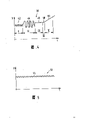
Fig. 4 is the plotted curve of the various working staties of expression;
Fig. 5 has the predetermined work state diagram of residual cavitation for expression;
Schematically illustrated a multistage evaporation equipment 10 among Fig. 1.The liquid that is collected in the first order in the liquid-container 12 is sent in the liquid-container 14 of next stage by centrifugal pump 16.Liquid has liquid level (horizontal plane) 20 there.
Further transmit liquid by pipeline 22 by centrifugal pump 18.At centrifugal pump 18 and conduit 22 on the pressure side, 24 places are measured cavitation erosion at branch road.Measured value input microprocessor 26, microprocessor is adjusted motor 30 to regulate the rotating speed of centrifugal pump 18 by frequency variator 28.
In total adjustment loop, adjust the rotating speed of centrifugal pump 18, the residual cavitation that makes it to keep minimum (following also will further specify) in conjunction with Fig. 4 and Fig. 5.
Fig. 3 has provided another embodiment, and wherein measuring diaphragm 32 is made arch, to guarantee desired mechanical stability when vacuum and the superpressure.
Fig. 4 represents by the voltage U that records on the measuring diaphragm various different operating states described of the change curve of t in time.
Wherein in the scope of representing with I, there is cavitation erosion 42, and shows pulsation 44 with the scope II.
Scope " III " expression normal working 46, normal working have provided again in the scope IV in the German open file 3236815 that beginning is mentioned specially as the represented situation of optimum Working 48.
The scope V has been described a filling curve 50, just describes a kind of state, and this is a kind of liquid level 20 when liquid-container 14 when raising, when rotating speed changes not enough back as the suction side filling of centrifugal pump among Fig. 1 18, and the state that is occurred.
By test, can affirm, in the drawings for the ease of watching, only in one-level, shown the adjusting part as the centrifugal pump 18(among Fig. 1) under the situation that adopts the inventive method, always operate in most effective best operating point near.As direct result is to obtain liquid-container 12 and 14 minimum possible flooded suctions, this can be from the fluid displacement that has reduced in the multistage milk evaporation equipment, less damage quality of product thereby shortened the currency, and product viscosity is lower etc., and the aspect reflects.
When for example the liquid-container in Fig. 1 equipment 14 being carried out filling, make it pressure and raise, produced more a spot of cavitation erosion.According to method adjustment of the present invention the rotating speed of centrifugal pump 18 is raise in this case, therefore guaranteed selected residual cavitation 54.
Because rotating speed improves, the amount of transmission also increases, and has promptly directly offset the filling of liquid capacity 14, makes it the flooded suction that keeps minimum.Xiang Guan horizontal plane 20 has guaranteed the short quiescent time and the waiting time of flowing fluid ratio therewith.
Another important advantage of the present invention is that the rotating speed of transmission equipment can change.Because can measure cavitation erosion, thus can determine a cavitation erosion limiting value, in this limiting value with device shutdown or give a warning.
When using water ring pump as transmission equipment, very big advantage of the present invention is to have reduced significantly the consumption of fresh water and the adding quantity of equalization gas or air, because can transfer very lowly, coordinate mutually and residual cavitation 54 is forced down in cavitation erosion up to the flow of pump and gas or the air amount of separating out by the rotating speed of method pump of the present invention.
Claims (12)
1, be adjusted at the method that transmits the transmission equipment of liquid and/or gas in the pipeline, wherein cavitation erosion measured, the output value as offering regulating device is characterized by, according to the cavitation erosion (42 that records; 54) transmission equipment (18) is adjusted, made residual cavitation (54) minimum.
2, in accordance with the method for claim 1, it is characterized by, residual cavitation (54) various concrete operating conditions when transmitting are correspondingly adjusted to different numerical value.
3, according to claim 1 and/or 2 described methods, it is characterized by, when the cavitation erosion value (42) that records surpasses adjustable cavitation erosion limiting value, transmission equipment (18) will be closed.
4, according to claim 1 and/or 2 described methods, it is characterized by, when the cavitation erosion value (42) that records surpasses adjustable cavitation erosion limiting value, will give a warning
5, according to the described method of one of claim 1 to 4 noted earlier, it is characterized by, cavitation erosion is measured by pressure transducer.
6, according to the described method of one of claim 1 to 5 noted earlier, it is characterized by, have measuring diaphragm (32) measuring guide (22) and transmission equipment (18) cavitation erosion on the pressure side of paper tinsel formula foil gauge (34) by means of at least one that is installed in conduit (22) tube wall.
7, according to the described method of one of claim 1 to 6 noted earlier, it is characterized by, resulting voltage (V) input microprocessor (26) is measured in cavitation erosion analyzed.
8, in accordance with the method for claim 7, it is characterized by, microprocessor (26) is controlled transmission equipment (18).
9, in accordance with the method for claim 8, it is characterized by, adopt centrifugal pump (18) as transmission equipment, the rotating speed of centrifugal pump (18) is adjusted by microprocessor (26).
10, according to the described method of one of claim 1 to 9 noted earlier, it is characterized by, adopt positive displacement pump as transmission equipment.
11, according to one of aforesaid right requirement 1 to 9 described method, it is characterized by, adopt water ring pump (vacuum pump) as transmission equipment.
12, according to the described method of one of claim 1 to 11 noted earlier, it is characterized by, microprocessor (26) is controlled the valve location of throttle valve in the pipeline (22).
Applications Claiming Priority (2)
| Application Number | Priority Date | Filing Date | Title |
|---|---|---|---|
| DE19853509072 DE3509072A1 (en) | 1985-03-14 | 1985-03-14 | METHOD FOR SETTING THE CAVITATION |
| DEP3509072.3 | 1985-03-14 |
Publications (1)
| Publication Number | Publication Date |
|---|---|
| CN86101484A true CN86101484A (en) | 1987-01-07 |
Family
ID=6265137
Family Applications (1)
| Application Number | Title | Priority Date | Filing Date |
|---|---|---|---|
| CN198686101484A Pending CN86101484A (en) | 1985-03-14 | 1986-03-11 | The method of control cavitation erosion |
Country Status (9)
| Country | Link |
|---|---|
| EP (1) | EP0194474B1 (en) |
| JP (1) | JPS61283779A (en) |
| CN (1) | CN86101484A (en) |
| AT (1) | ATE96505T1 (en) |
| AU (1) | AU5471386A (en) |
| DE (2) | DE3509072A1 (en) |
| DK (1) | DK107386A (en) |
| FI (1) | FI861033A (en) |
| ZA (1) | ZA861395B (en) |
Cited By (5)
| Publication number | Priority date | Publication date | Assignee | Title |
|---|---|---|---|---|
| CN101520391B (en) * | 2009-04-01 | 2011-01-05 | 奇瑞汽车股份有限公司 | Cavitation erosion test method of engine cooling system stand |
| CN102817649A (en) * | 2011-06-09 | 2012-12-12 | 株式会社神户制钢所 | Power generation apparatus |
| CN103576640A (en) * | 2012-07-31 | 2014-02-12 | 费希尔-罗斯蒙特系统公司 | Systems and methods to monitor pump cavitation |
| CN107186911A (en) * | 2016-03-14 | 2017-09-22 | 株式会社神户制钢所 | Resin granulator device and cavitation erosion monitoring method |
| CN107906058A (en) * | 2017-10-31 | 2018-04-13 | 中广核工程有限公司 | A kind of monitoring system and method for preventing nuclear power plant's vacuum pump cavitation |
Families Citing this family (8)
| Publication number | Priority date | Publication date | Assignee | Title |
|---|---|---|---|---|
| DE19517289A1 (en) * | 1995-05-11 | 1996-11-14 | Klein Schanzlin & Becker Ag | Monitoring system for determining a cavitation intensity |
| DE19645129A1 (en) * | 1996-11-04 | 1998-05-07 | Abb Patent Gmbh | Cavitation protection of pump governed according to rotational speed |
| DE19815242A1 (en) * | 1998-04-04 | 1999-10-07 | Rossendorf Forschzent | Arrangement for preventing a cavitation blow when a pipeline used for transporting liquids is quickly shut off |
| DE19826292A1 (en) * | 1998-06-12 | 1999-12-23 | Linde Ag | Process for operating a pump to convey boiling refrigerants or refrigerants |
| DE19858946A1 (en) * | 1998-12-09 | 2000-06-15 | Ver Energiewerke Ag | Detecting cavitation in multiple stage centrifugal pump involves comparing pressure difference between input and one pump stage with desired delivery value for a pump stage |
| CN109681474B (en) * | 2019-01-21 | 2023-08-18 | 中国科学院工程热物理研究所 | Automatic adjusting device and method for inhibiting cavitation of centrifugal pump |
| CN110307469A (en) * | 2019-07-24 | 2019-10-08 | 中国海洋石油集团有限公司 | A kind of LNG receiving station high pressure pump system and its control method |
| CN110985449B (en) * | 2019-12-04 | 2020-10-30 | 武汉理工大学 | Large-scale mail steamer water supply system and centrifugal pump cavitation erosion prevention device |
Family Cites Families (10)
| Publication number | Priority date | Publication date | Assignee | Title |
|---|---|---|---|---|
| AT306402B (en) * | 1970-12-23 | 1973-04-10 | List Hans | Strain gauge transducers, especially pressure transducers |
| JPS5177905A (en) * | 1974-12-27 | 1976-07-06 | Tokyo Shibaura Electric Co | DENJIHON PUSOCHI |
| US4330238A (en) * | 1980-03-04 | 1982-05-18 | The United States Of America As Represented By The Secretary Of The Navy | Automatic actuator for variable speed pump |
| JPS57105580A (en) * | 1980-12-19 | 1982-07-01 | Hitachi Zosen Corp | Control method for pump operation |
| JPS57159981A (en) * | 1981-03-30 | 1982-10-02 | Hitachi Constr Mach Co Ltd | Abnormal pressure indicator in suction side circuit of hydraulic pump |
| JPS57183582A (en) * | 1981-05-08 | 1982-11-11 | Hitachi Zosen Corp | Operational control method of pump |
| CH651111A5 (en) * | 1982-07-28 | 1985-08-30 | Cerac Inst Sa | PUMPING INSTALLATION AND METHOD FOR ACTIVATING THE SAME. |
| DE3236815C2 (en) * | 1982-10-05 | 1985-09-19 | Klaus Dipl.-Ing.(FH) 3200 Hildesheim Metzger | Monitoring and control device on pipelines for the transport of liquids |
| JPS5968582A (en) * | 1982-10-14 | 1984-04-18 | Mitsubishi Heavy Ind Ltd | Automatic setting device of cavitation limit of dredge pump |
| FR2535408A1 (en) * | 1982-10-28 | 1984-05-04 | Snecma | DEVICE AND METHOD FOR DETECTING CUSTODY AT CAVITATION OF A VOLUMETRIC PUMP |
-
1985
- 1985-03-14 DE DE19853509072 patent/DE3509072A1/en active Granted
-
1986
- 1986-02-18 AT AT86102057T patent/ATE96505T1/en not_active IP Right Cessation
- 1986-02-18 EP EP86102057A patent/EP0194474B1/en not_active Revoked
- 1986-02-18 DE DE86102057T patent/DE3689199D1/en not_active Revoked
- 1986-02-25 ZA ZA861395A patent/ZA861395B/en unknown
- 1986-03-10 DK DK107386A patent/DK107386A/en not_active Application Discontinuation
- 1986-03-11 CN CN198686101484A patent/CN86101484A/en active Pending
- 1986-03-13 FI FI861033A patent/FI861033A/en not_active Application Discontinuation
- 1986-03-13 JP JP61056024A patent/JPS61283779A/en active Pending
- 1986-03-13 AU AU54713/86A patent/AU5471386A/en not_active Abandoned
Cited By (9)
| Publication number | Priority date | Publication date | Assignee | Title |
|---|---|---|---|---|
| CN101520391B (en) * | 2009-04-01 | 2011-01-05 | 奇瑞汽车股份有限公司 | Cavitation erosion test method of engine cooling system stand |
| CN102817649A (en) * | 2011-06-09 | 2012-12-12 | 株式会社神户制钢所 | Power generation apparatus |
| CN102817649B (en) * | 2011-06-09 | 2015-05-13 | 株式会社神户制钢所 | Power generation apparatus |
| CN103576640A (en) * | 2012-07-31 | 2014-02-12 | 费希尔-罗斯蒙特系统公司 | Systems and methods to monitor pump cavitation |
| CN103576640B (en) * | 2012-07-31 | 2019-04-30 | 费希尔-罗斯蒙特系统公司 | System and method for monitoring pump cavitation |
| CN107186911A (en) * | 2016-03-14 | 2017-09-22 | 株式会社神户制钢所 | Resin granulator device and cavitation erosion monitoring method |
| CN107186911B (en) * | 2016-03-14 | 2020-10-16 | 株式会社神户制钢所 | Resin pelletizer apparatus and cavitation monitoring method |
| CN107906058A (en) * | 2017-10-31 | 2018-04-13 | 中广核工程有限公司 | A kind of monitoring system and method for preventing nuclear power plant's vacuum pump cavitation |
| CN107906058B (en) * | 2017-10-31 | 2019-07-23 | 中广核工程有限公司 | A kind of monitoring system and method preventing nuclear power plant's vacuum pump cavitation |
Also Published As
| Publication number | Publication date |
|---|---|
| EP0194474A3 (en) | 1989-03-08 |
| DE3509072A1 (en) | 1986-09-25 |
| FI861033A0 (en) | 1986-03-13 |
| DK107386A (en) | 1986-09-15 |
| EP0194474B1 (en) | 1993-10-27 |
| AU5471386A (en) | 1986-09-18 |
| EP0194474A2 (en) | 1986-09-17 |
| DE3689199D1 (en) | 1993-12-02 |
| FI861033A (en) | 1986-09-15 |
| DK107386D0 (en) | 1986-03-10 |
| ATE96505T1 (en) | 1993-11-15 |
| JPS61283779A (en) | 1986-12-13 |
| ZA861395B (en) | 1986-11-26 |
| DE3509072C2 (en) | 1987-06-25 |
Similar Documents
| Publication | Publication Date | Title |
|---|---|---|
| CN86101484A (en) | The method of control cavitation erosion | |
| CN105674954A (en) | Transparent double-measurement-system static force level gauge and use method thereof | |
| CN2428764Y (en) | Mechanical sealing test apparatus with controllable spring specific-pressure and measurable vibration | |
| CN1216275C (en) | Non-insertion method of measuring fluid pressure and flow rate inside pipe | |
| RU2328597C1 (en) | Process and device of oil well yield measurement at group facilities | |
| EP3164678A1 (en) | Measurement of flow through pipelines | |
| CN1221792C (en) | Device of combined sensor in use for measuring dynamical pressure and static pressure in deep sea | |
| CN103597268A (en) | Method for determining condition of piping and sequence controlled sample pump | |
| DE3236815A1 (en) | Monitoring and inspection device on pipelines for the transport of liquids for suppressing cavitation and improving the operating conditions | |
| CN1056234C (en) | Fluid-detecting measuring device | |
| CN201935758U (en) | Device for testing dynamic friction force of pneumatic control valve | |
| CN1037940A (en) | In paper and board machine head box, reduce the attenuator of pressure oscillation effectively | |
| CN112484796A (en) | Experiment platform and method for calibrating flow of regulating valve by sound wave signal | |
| JPS60100739A (en) | Viscosity measuring device | |
| CN217155467U (en) | Water cooling equipment flow, flow resistance and suppress testing arrangement | |
| CN217006504U (en) | Water quality sample collecting device for microbial water quality detection | |
| CN111457987A (en) | Concrete resistance value calibration device and method for super-irrigation monitoring system | |
| JP7431148B2 (en) | Pump operation control method, discharge flow rate derivation method, and discharge flow rate control method | |
| CN214793617U (en) | Pointer type micro differential pressure gauge calibration device | |
| CN215491883U (en) | System for accurately measuring oil well yield and crude oil water content in oil field | |
| CN113153725B (en) | Water pump testing system and method | |
| CN109895947B (en) | Fluid excitation vibration influence weakening system and method applied to ship seawater system | |
| SU565976A1 (en) | Testing stand for studying the operation of a suction dredge | |
| SU756238A1 (en) | Pressure sensor calibration device | |
| RU2365878C2 (en) | Fluid flow metre of variable pressure drop |
Legal Events
| Date | Code | Title | Description |
|---|---|---|---|
| C10 | Entry into substantive examination | ||
| SE01 | Entry into force of request for substantive examination | ||
| C06 | Publication | ||
| PB01 | Publication |