EP0194431B1 - High-pressure fuel injection device for a combustion engine - Google Patents
High-pressure fuel injection device for a combustion engine Download PDFInfo
- Publication number
- EP0194431B1 EP0194431B1 EP86101067A EP86101067A EP0194431B1 EP 0194431 B1 EP0194431 B1 EP 0194431B1 EP 86101067 A EP86101067 A EP 86101067A EP 86101067 A EP86101067 A EP 86101067A EP 0194431 B1 EP0194431 B1 EP 0194431B1
- Authority
- EP
- European Patent Office
- Prior art keywords
- pressure
- valve
- control
- pump
- delivery
- Prior art date
- Legal status (The legal status is an assumption and is not a legal conclusion. Google has not performed a legal analysis and makes no representation as to the accuracy of the status listed.)
- Expired
Links
Images


Classifications
-
- F—MECHANICAL ENGINEERING; LIGHTING; HEATING; WEAPONS; BLASTING
- F02—COMBUSTION ENGINES; HOT-GAS OR COMBUSTION-PRODUCT ENGINE PLANTS
- F02M—SUPPLYING COMBUSTION ENGINES IN GENERAL WITH COMBUSTIBLE MIXTURES OR CONSTITUENTS THEREOF
- F02M59/00—Pumps specially adapted for fuel-injection and not provided for in groups F02M39/00 -F02M57/00, e.g. rotary cylinder-block type of pumps
- F02M59/20—Varying fuel delivery in quantity or timing
- F02M59/36—Varying fuel delivery in quantity or timing by variably-timed valves controlling fuel passages to pumping elements or overflow passages
- F02M59/361—Valves being actuated mechanically
-
- F—MECHANICAL ENGINEERING; LIGHTING; HEATING; WEAPONS; BLASTING
- F02—COMBUSTION ENGINES; HOT-GAS OR COMBUSTION-PRODUCT ENGINE PLANTS
- F02M—SUPPLYING COMBUSTION ENGINES IN GENERAL WITH COMBUSTIBLE MIXTURES OR CONSTITUENTS THEREOF
- F02M59/00—Pumps specially adapted for fuel-injection and not provided for in groups F02M39/00 -F02M57/00, e.g. rotary cylinder-block type of pumps
- F02M59/20—Varying fuel delivery in quantity or timing
- F02M59/36—Varying fuel delivery in quantity or timing by variably-timed valves controlling fuel passages to pumping elements or overflow passages
- F02M59/366—Valves being actuated electrically
-
- F—MECHANICAL ENGINEERING; LIGHTING; HEATING; WEAPONS; BLASTING
- F02—COMBUSTION ENGINES; HOT-GAS OR COMBUSTION-PRODUCT ENGINE PLANTS
- F02M—SUPPLYING COMBUSTION ENGINES IN GENERAL WITH COMBUSTIBLE MIXTURES OR CONSTITUENTS THEREOF
- F02M2200/00—Details of fuel-injection apparatus, not otherwise provided for
- F02M2200/24—Fuel-injection apparatus with sensors
Definitions
- the invention relates to a high-pressure fuel injection device on internal combustion engines with features of the type specified in the preamble of claim 1.
- a similar fuel injector for generating low to medium injection pressures is known from "Patents abstracts of Japan", Volume 8, No. 220 (M330), (1657), October 6, 1984 to JP-A-59 103 960.
- an electromagnetic valve connects a supply line coming from the fuel feed pump via the bore of a hollow needle-shaped metering valve to the pressure chamber of a high-pressure injection pump.
- the solenoid valve closes the connection between the rear end of the metering valve and the supply line when the cam-driven high-pressure ram moves downward.
- the larger rear surface is acted upon by the pressure building up in the high-pressure chamber and closes a connection between the high-pressure chamber and a return flow line with a conical valve seat arranged on its smaller front surface.
- a valve needle spring-loaded in the closing direction is raised from its seat and the injection openings are opened.
- the solenoid valve is opened. The metering valve then releases the connection from the high-pressure space or from the fuel storage space to the return line when the rear surface is relieved.
- the invention is therefore based on the object of developing a fuel injection device on which the preamble of patent claim 1 is based so that, with great operational reliability, this enables an extremely steep pressure build-up even at very high injection pressures and very small injection quantities.
- the high-pressure fuel injection device shown in the drawing and arranged on internal combustion engines generally comprises a high-pressure injection pump 1, which in terms of its structure consists of a lower part 2, in which the fuel delivery and pressure generation takes place, and a pump head 3, put together.
- a high-pressure injection pump 1 which in terms of its structure consists of a lower part 2, in which the fuel delivery and pressure generation takes place, and a pump head 3, put together.
- the pump piston 5 in a pump cylinder bore 4
- there is a pump piston 5 without a control edge which is controlled by a cam 8 of a camshaft 9 via a pump tappet 6 with roller 7 and with its upper flat end face 10 together with the wall parts of the pump cylinder bore 4
- Pump pressure chamber 11 limited.
- the high-pressure injection pump 1 is designed for the delivery of fuel with a pressure in the order of up to approximately 1500 bar.
- the pump piston 5 can supply fuel to an injection valve 15 from the pump pressure chamber 11 via a delivery channel 12 branching off from it and a pressure valve 13 which is known per se due to its structure and is only permeable in the direction of delivery, as well as a connecting line 14 connected thereto.
- a pressure relief duct 16 branches off from the connecting line 14, which opens into the pump pressure chamber 11 and into which a pressure relief valve 17 that only allows fuel to flow towards the pressure chamber is switched on.
- This pressure relief valve 17 serves to rapidly reduce the fuel pressure given in the connecting line 14 to a certain residual pressure level after the end of the delivery of the high-pressure injection pump.
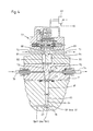
- This one-way suction valve 21 is preferably installed in the pump head 3 of the high-pressure injection pump 1 and has one. Equipment such as shown in Fig. 6.
- the one-way suction valve 21 consists of a valve sleeve 22, which is inserted into a receiving bore 23 of the pump head 3 and is locked in the installed position by a holding plate 24 screwed to the pump head 3.
- valve sleeve 22 has a connection thread 25 for connecting the inlet-side part of the feed line 20.
- the one-way suction valve-internal part of the feed line 20 is formed by a through hole 26, at the end of which a conical valve seat ring surface 27 connects, which leads into an enlarged fuel passage space 28 merges into which is connected a receiving bore 29 which extends through to the rear end for a valve body 30 which is axially displaceable therein.
- the valve body 30 has at its front end a conical valve cone 31 which cooperates with the valve seat ring surface 27, furthermore a fuel passage bore 32 drilled from the rear, designed as a blind hole, and transverse bores 33 which establish a continuous passage connection between the fuel passage bore 32 and the fuel passage space 28.
- the valve body 30 is acted upon by a compression spring 34 in the closing direction, that is to say from its rear side.
- the feed line 20 is formed within the one-way suction valve, i.e. through the bore 26, the fuel passage space 28, the passage transverse bores 33 and the fuel passage bore 32, and continues within the pump head 3 in the form of a bore 35, a transverse bore 36 and a bore 37, the latter of which opens into the pump pressure chamber 11 of the high-pressure injection pump 1.
- a return line 38 leading to the tank branches off directly from the pump pressure chamber (see FIG. 2) or from the delivery channel running between the latter and the pressure valve (see FIGS. 1 and 3).
- a combined passage and dynamic pressure shut-off valve 39 is switched on.
- An embodiment for this passage and dynamic pressure shut-off valve is shown in FIG. 6. It is preferably installed in the pump head 3 similarly to the one-way suction valve 21 and consists of a valve sleeve 40 which is inserted in a receiving bore 41 and is locked in the installation position on the pump head.
- valve sleeve 40 there is an inlet bore 42 which is in constant communication with the inlet-side part 38/1 of the return line, which is inside the pump head 3 through a bore branching off from the pump pressure chamber 11 or the delivery channel 12 and a transverse bore 43 and the rear free bore Part 44 of the receiving bore 41 for the valve sleeve 40 is formed.
- a conical valve seat ring surface 45 adjoins the valve sleeve, in turn an overflow chamber 46 and behind it a receiving bore 47 for a valve body 48 which can be axially displaced therein between two end positions.
- valve body 48 In its one end position, the valve body 48 shuts off the return line 38 with its valve seat 49 pressed against the valve seat ring surface 45, while on the other hand it releases the return line away from this end position.
- the valve body 48 can be pressed in the direction of the valve seat ring surface 45 by a rear part engaging on its rear part opposite the valve seat 49 and exerting a pressure force slightly below the feed pressure of the low-pressure feed pump 18.
- the overflow space 46 is in permanent passage connection via transverse bores 51 with an annular outflow space 52 located outside the valve sleeve, which is connected to the downstream part 38/2 of the return line 38.
- the valve body 48 has a continuous channel 53 with a throttle bore 54. Through this channel 53 and the throttle bore 54, fuel constantly flows from the inlet-side part 38/1 of the return line 38 into a dynamic pressure chamber 55 acting downstream of the throttle bore and from there into a dynamic pressure control line 56 connected to it (see also FIGS. 1 to 3).
- the dynamic pressure chamber 55 is formed by the part of the channel 53 which is behind the throttle bore 54 in terms of flow.
- the dynamic pressure control line 56 branches - as can be seen from FIGS. 1, 2 and 3 - into two parallel branches 56/1 and 56/2, which are separated from one another downstream of the branch point 57 (as shown in FIGS. 2 and 3) or again merged into a line part 58 via this (as shown in FIG. 1) open into the part 38/2 of the return line 38 which is downstream of the passage and dynamic pressure shut-off valve 39.
- a controlled one-way valve 59 and 60 is switched on in each of the two parallel branches 56/1, 56/2 of the dynamic pressure control line 56.
- the one-way valve 59 is hereinafter referred to as the "start of delivery one-way valve 59" and the one-way valve 60 as the "end of delivery one-way valve 60".
- the delivery start one-way valve 59 marks the start of delivery of the high-pressure injection pump 1 at the moment of its closing with the delivery end one-way valve 60 closed, while the delivery end one-way valve 60 marks the delivery end of the high-pressure injection pump 1 when it opens.
- both the start of delivery one-way valve 59 and the end of delivery one-way valve 60 are connected to their own actuating device 61 or 62 (FIGS. 1, 2 and 3) and this in turn is connected to a control device 63 which actuates the two one-way valves synchronously with the machine 59, 60 in the sense of operationally optimized values for the start and end of delivery of the high-pressure injection pump 1 controls.
- each of the two one-way valves 59, 60 has a valve body 65 which is received in an axially displaceable manner in a receiving bore 64.
- the latter has at its front end a preferably conical valve seat 66 which interacts with a correspondingly adapted conical valve seat ring surface 67.
- This valve seat ring surface 67 is formed by a conical widening on the inlet-side part of the respective parallel branch 56/1 or 56/2 of the dynamic pressure control line 56.
- the valve body 65 can be pressed by pressurization on its rear side opposite the valve cone in the closed position, in which the respective parallel branch 56/1 or 56/2 is shut off, and when the rear of the valve is relieved of pressure by the fuel pressure in at its front side having the valve seat 66 Pass position in which the respective parallel branch 56/1 or 56/2 is switched through, displaceable.
- valve body 65 of each of the two one-way valves 59 and 60 can directly z. B. by an electro-hydraulic servo valve or, as shown in Fig. 4, with the interposition of a pressure piston 68 from a pressure chamber, which is switched into a hydraulic high-pressure control circuit.
- the latter forms part of the actuating device.
- the introduction of a liquid high-pressure control medium to the pressure chamber 69 takes place via a high-pressure supply line 70, which continues as a bore within a control block 71 and can be released or blocked by the valve body 72 of a control valve 73.
- the liquid high-pressure control medium supplied to the pressure chamber 69 is deactivated via a high-pressure discharge line 74, which is likewise formed within the control block by bores and can be switched through or shut off by the valve body 75 of a further control valve 76.
- Each of the two valve bodies 72 and 75 has at its front end a valve cone which interacts with a correspondingly designed valve seat ring surface in the part of the high-pressure supply line 70 or high-pressure line 74 inside the control block.
- the opening and closing of the two control valves 73 and 76 is controlled by an electro-hydraulic servo valve 77 which is electronically activated by the control device. This servo valve 77 is of a known type and therefore need not be explained in detail here.
- FIG. 4 From the hydraulic auxiliary control circuit, only a feed line 78 for hydraulic control medium is shown in FIG. 4, which leads to an input of the servo valve 77 and a return line 79 branching off at an output of the servo valve 77.
- the hydraulic control medium can expediently be the fuel that is also used for the internal combustion engine.
- a pressure chamber 81 is connected to the one control output of the servo valve 77 via a control pressure line 80 at the rear of a pressure piston 82 acting in the closing direction on the valve body 72 of the control valve 73.
- a pressure chamber 84 is connected to a second control output of the servo valve 77 via a control pressure line 83, which pressure chamber 85 acts on the back of a pressure piston 85 acting in the closing direction on the valve body 75 of the control valve 76 is arranged.
- the servo valve is designed for the control of extremely short switching times in the millisecond range, so that the hydraulic auxiliary control circuit and the two control valves 73, 76 and the hydraulic high-pressure control circuit provide extremely precise pressure relief and relief of the pressure chamber 69 and thus extremely precise opening and closing of one Parallel branch 56/1 or 56/2 of the dynamic pressure control line 56 are guaranteed by the respective one-way valve 59 or 60.
- the servo valve 77 is connected to the electronic control device 63, which, as shown in FIGS. 1 to 3, is continuously signaled by a resolver 86 that the rotational angle position of the camshaft 9 is signaled via a signal line 87 and on the basis of these rotational angle messages and a special control program controls the respective servo valve 77. This control characteristic is explained further below in connection with the functional description of the high-pressure fuel injection device according to the invention.
- both one-way valves 59, 60 are each of identical design and are installed here in the pump head 3 of the high-pressure injection pump 1.
- Each of the two one-way control valves 59, 60 consists of a valve sleeve 90 installed in a receiving bore 88 of the pump head 3 and held in the installed position by a strip 89 fastened to the pump head.
- the valve body 65 is axially displaceably mounted between two end positions and in the closing direction from its rear side forth by a closing pressure spring 91.
- valve body 65 In its one end position the valve body 65 is pressed with a conical valve seat 92 against a correspondingly adapted valve seat ring surface 93 and in its other end position it is moved away from it.
- a fuel control chamber 94 connects to the valve seat ring surface 93 in front of the valve seat 92 of the valve body 65, which, via a transverse through bore 95 and a blind hole 96 drilled from the rear of the valve body 65, connects to the inlet-side part of a parallel branch 56/1 or 56/2 Dynamic pressure control line 56 is supplied with fuel.
- an annular fuel outlet space 97 adjoins the valve seat annular surface 93 and is connected via at least one transverse bore 98 to an annular fuel outflow chamber 99 surrounding the valve sleeve within the receiving bore 88. From the latter, the outlet-side part of the respective parallel branch 56/1 or 56/2 of the dynamic pressure control line 56 branches off, which flows into the return line 38 separately or together, as already mentioned above.
- an actuating rod 100 is arranged on the valve body 65 in one piece and coaxially therewith, which is guided in a receiving bore 101 of the valve sleeve 90.
- a plunger 102 forming part of the actuating device 61 or 62 engages on the front end face of the actuating rod 100 of the valve body 65. This is axially displaceably guided coaxially to the valve body in a receiving bore 103 and, under the action of a compression spring 104 acting on its rear side, is pressed against the peripheral control link 106 of a control sleeve 107 by a scanning roller 105 which is rotatably mounted in the region of its front end.
- the design of the control sleeve 107 and the control and confirmation members assigned to it can be seen in FIG. 5 and will be described below with reference to this. In FIG.
- Each of the two control sleeves 107 is arranged axially parallel to the pump piston 5 of the high-pressure injection pump 1 and is guided in a guide bore 108.
- the latter is formed in the illustrated embodiment as a through hole in a sleeve 109 inserted into the pump head 3.
- the control sleeve 107 is seated both against rotation and axially secured on a coaxially arranged actuating piston 110, which is guided in guide bores 111, 112 and acted on via the control sleeve 107 by a compression spring 113 countered in the pump head, under the action of which the lower end is pressed against a pressure plate 114 is.
- the pressure plate 114 itself is articulated to the pump piston 5 or its plunger 6 via a sleeve 115 formed integrally with it and synchronizes with the latter's stroke movements.
- Each peripheral surface 106 of a control sleeve 107 is designed as a control link for the actuation of a valve body 65.
- the two control links are different from one another, because with one control link 116, hereinafter referred to as "start of delivery control link 116", the valve body 65 of the start of delivery one-way valve 59 can be controlled, while with the other control link 117, hereinafter referred to as “end of delivery control link 117", the valve body 65 of the delivery end one-way valve 60 is controllable.
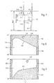
- 8 shows the handling of the start of funding.
- Control link 116 and from FIG. 9 the handling of the end of delivery control link 117 can be seen.
- the start of conveying control link 116 is composed of a raised control surface region 118, hatched in FIG. 8, and a recessed peripheral region 119, which is adjacent in the axial direction.
- the transition between these two peripheral regions 118, 119 of the control sleeve 107 is formed by an oblique control edge 120 which determines the start of delivery.
- the conveying end control link 117 is likewise composed of a raised, hatched area in FIG. 9 on the control sleeve 107 and an axially recessed peripheral area 122.
- the transition between the two peripheral regions 121 and 122 is formed by an oblique control edge 123 that determines the end of the conveying end.
- the circumferential regions 118 and 121 shown hatched in FIGS. 8 and 9 lie on the respective control sleeve 107 with the same diameter in each case.
- Both the start of delivery control link 116 and the end of delivery control link 117 can each be brought into a specific position with respect to the scanning roller 105 by rotating the associated control sleeve 107.
- each of the two control sleeves 107 is assigned a control rod 126 or 127, which is received in a receiving bore 128 of the pump head 3, which is perpendicular to the actuating piston 110, and with its toothing in a toothing 129 on Actuating piston 110 engages.
- Each of the two control rods 126 and 127 is axially reciprocated by an actuating element (not shown), which receives its setting commands from a controller or an electronic control unit 63, for rotating the connected control sleeve 107 and thus for adjusting the respective oblique control edge 120 or 123 slidable.
- the pump piston 5 of the high-pressure injection pump 1 is in the bottom dead center position, which is indicated in FIG. 7 by the transverse line labeled UT, then the one-way suction valve 21 is open; in addition, the one-way delivery valve 59 is in the open position because the scanning roller 105, as can be seen in FIG. 7, rests in the raised peripheral region 118 of the control link 116 and the valve cone 92 on the valve body 65 of the one-way delivery valve 59 has moved away from its valve seat ring surface 93 .
- the associated control sleeve 107 is also in its lowest dead center position, which is also marked in FIG. 7 by the transverse line labeled UT.
- a fuel flow from the low-pressure feed pump 18 is thereby promoted via the open one-way suction valve 21 to the pump pressure chamber 11 of the high-pressure injection pump and from there via the return line 38 and the now also open passage and dynamic pressure shut-off valve 39 back to the tank.
- the passage and dynamic pressure shut-off valve 39 is open because it is not acted upon by any dynamic pressure on its rear side and by the fuel feed pressure in the order of magnitude of 3 to 10 bar acting on its front side against the force of the closing pressure spring 50 with its valve seat 49 from the valve seat ring surface 45 is lifted off.
- the fuel present in the inlet-side part 38/1 of the return line 38 can also flow freely through the throttle bore 54 in the passage and dynamic pressure shut-off valve and pass through the dynamic pressure control line 56 and its now open parallel branch 56/1 into the return line 38 and flow back to the tank via this . From this it can be seen that at this stage the high-pressure injection pump 1 is completely flowed through by fuel.
- the one-way suction valve 21 initially closes because its valve cone 31 is pressed against the valve seat ring surface 27 by the pressure build-up in the pump pressure chamber 11, which propagates via the conduit paths 37, 36 and 35.
- the passage and back pressure shut-off valve 39 is still open at this stage of the upward stroke of the pump plunger 5.
- the conveying end one-way valve 60 has been in the closed position up to this stage, as already indicated earlier, because the associated scanning roller 105, as can be seen in FIG. 7, is in the recessed area 122 of the control link 117 on the control sleeve belonging to this one-way valve 60 107 moves and thereby the valve cone 92 is pressed by its valve body onto the associated valve seat ring surface 93.
- the pressure build-up within the pump pressure chamber 11 of the high-pressure injection pump 1 is controlled in a conventional manner by the contour of the control cam 8, the fuel delivered being conveyed via the pressure valve 13 arranged on the pump outlet side and the connecting line 14 to the injection valve 15 and via the latter into the connected combustion chamber is injected.
- the start of delivery one-way valve 59 remains closed during the entire subsequent delivery stroke of the pump piston 5, because the associated scanning roller 105 moves in the recessed partial region 119 of the control link 116 on the associated control sleeve 107.
- the delivery end of the high-pressure injection pump 1 occurs when the control sleeve 107 assigned to it, with its oblique control edge 123, moves the scanning roller 105 and the latter then comes into contact with the raised part 121 of the control link 117, as a result of which the valve cone 92 on the valve body 65 of the delivery end One-way valve 60 is moved away from the associated valve seat ring surface 93 and held in the open position.
- the pump piston 5 delivers fuel from the pressure chamber 11 essentially only via the return line 38 and the open passage and dynamic pressure shut-off valve 39 back into the tank.
- the delivery end one-way valve 60 is subsequently closed again because the associated scanning roller 105 again passes through the inclined control edge 123 into the recessed area 122 of the associated control sleeve 107, as a result of which the valve body 65 of the delivery end one-way valve 60 is in again its closed position is traceable and then rests with its valve seat 92 on the associated valve seat ring surface 93. Then the parallel branch 56/2 of the dynamic pressure control line 56 is shut off again, so that no fuel can flow back to the tank via this line path.
- the scanning roller 105 assigned to the start of delivery one-way valve 59 still moves for a certain period of time, namely until the oblique control edge 120 is reached, in the recessed part 119 of the associated control sleeve 107, so that the start of delivery one-way valve 59 is closed and thus also no fuel can flow back to the tank via the parallel branch 56/1 of the dynamic pressure control line 56.
- the change and the optimal setting of the control times "start of delivery” and “end of delivery” of the high-pressure injection pump takes place via corresponding commands which the electronic control device 63 receives via channels 130 from a command status or directly depending on operating values of the sensors detecting the internal combustion engine.
- the high-pressure fuel injection device offers the possibility of any change in these control times while the high-pressure injection pump is running.
- extremely quickly and effectively changing operating states of the internal combustion engine or changing, in particular deteriorating operating values, such as deteriorating fuel quality or certain conditions of the charge air can be taken into account by appropriately adjusting the start and end of delivery of the high-pressure injection pump.
- the high-pressure injection pump has no sloping control edges on the pump plunger and no suction holes in the wall of the pump cylinder, extremely high volumetric efficiencies can be achieved, even at the highest pressures.
Description
Die Erfindung betrifft eine Kraftstoffhochdruck-Brennstoffeinspritzvorrichtung an Brennkraftmaschinen mit Merkmalen der im Oberbegriff des Anspruches 1 angegebenen art.The invention relates to a high-pressure fuel injection device on internal combustion engines with features of the type specified in the preamble of
Eine ähnliche Brennstoffeinspritzvorrichtung zur Erzeugung niederer bis mittlerer Einspritzdrücke ist aus dem "Patents abstracts of Japan", Band 8, Nr. 220 (M330), (1657), 06. Oktober 1984 zu JP-A-59 103 960 bekannt. Ein elektromagnetisches Ventil verbindet dort in geöffneter Stellung eine von der Brennstofförderpumpe kommende Zufuhrleitung über die Bohrung eines hohlnadelförmigen Zumeßventils mit dem Druckraum einer Hochdruckeinspritzpumpe. Gleichzeitig wird bei geöffnetem Magnetventil die rückwärtige Fläche des Zumeßventils mit der Zufuhrleitung verbunden und somit druckentlastet. Zur Festlegung des Einspritzbeginns schließt bei sich abwärtsbewegendeim, nockengetriebenem Hochdruckstempel das Magnetventil die Verbindung zwischen rückwärtigem Ende des Zumeßventils und der Zufuhrleitung. Ober die drosselartig ausgebildete Bohrung im Zumeßventil wird dessen größere rückwärtige Fläche vom sich aufbauenden Druck im Hochdruckraum beaufschlagt und verschließt mit einem an seiner flächenkleineren Vorderseite angeordneten kegeligen Ventilsitz eine Verbindung zwischen Hochdruckraum und einer Rückströmleitung. Durch den daraufhin im Brennstoffvorlageraum eines Einspritzventils entstehenden Druck wird eine in Schließrichtung federbeaufschlagte Ventilnadel von ihrem Sitz angehoben und die Einspritzöffnungen werden freigegeben. Zur Beendigung des Einspritzvorganges wird das Magnetventil geöffnet. Das Zumeßventil gibt daraufhin bei Entlastung seiner rückwärtigen Fläche die Verbindung vom Hochdruckraum bzw. vom Brennstoffvorlageraum zur Rückleitung frei.A similar fuel injector for generating low to medium injection pressures is known from "Patents abstracts of Japan",
Bei dieser bekannten Anordnung ist nachteilig, daß das Magnetventil gegen den hohen Brennstoffdruck geschlossen und während des Einspritzvorganges in dieser Lage gehalten werden muß. Bei sehr hohen Einspritzdrücken wären dazu entsprechend große Magnete erforderlich. Außerdem sind die Schaltzeiten von Magnetventilen relativ groß und daher ungeeignet, den für eine günstige Verbrennung gewünschten steilen Druckaufbau herbeizuführen. Die Trägheit dieser Ventilbauart bedeutet bei Verwendung eines einzigen Ventils außerdem, daß die bei einem Schließvorgang und einem unmittelbar anschließenden Öffnungsvorgang benötigte, relativ hohe Gesamtansprechzeit eine bestimmte Mindesteinspritzmenge bedingt, die nicht unterschritten werden kann.In this known arrangement it is disadvantageous that the solenoid valve must be closed against the high fuel pressure and must be kept in this position during the injection process. At very high injection pressures, correspondingly large magnets would be required. In addition, the switching times of solenoid valves are relatively long and therefore unsuitable to bring about the steep pressure build-up desired for cheap combustion. The inertia of this type of valve means, when using a single valve, that the relatively high total response time required for a closing process and an immediately subsequent opening process requires a certain minimum injection quantity which cannot be undercut.
Der Erfindung liegt daher die Aufgabe zugrunde, eine dem Oberbegriff des Patentanspruchs 1 zugrunde liegende BrennstoffEinspritzvorrichtung so weiterzubilden, daß diese bei großer Betriebssicherheit einen extrem steilen Druckaufbau auch bei sehr hohen Einspritzdrücken und sehr kleinen Einspritzmengen ermöglicht.The invention is therefore based on the object of developing a fuel injection device on which the preamble of
Diese Aufgabe wird durch die im Kennzeichen des Anspruchs 1 angegebenen Merkmale gelöst.This object is achieved by the features specified in the characterizing part of
Eine dem gattungsbildenden japanischen Abstract nahezu identische Anordnung - mit denselben Nachteilen wie jene - ist aus der DE-A-2 742 466 bekannt.An arrangement almost identical to the generic Japanese abstract - with the same disadvantages as that - is known from DE-A-2 742 466.
Eine Anwendung von zwei getrennten Schaltventilen zur Steuerung von Einspritzbeginn und Einspritzende ist prinzipiell bereits aus der US-A-4 326 672 bekannt. Die dort verwendeten Drehschieberventile sind jedoch aufgrund der auftretenden Dichtungsprobleme für Hochdruck-Einspritzvorrichtungen ungeeignet. Die in einer vorteilhaften Ausgestaltung der Erfindung verwendeten Steuer- und Servoventile sind für sich gesehen in einer anderen Anordnung aus der auf die Anmelderin zurückgehenden FR-A-2 316 450 bekannt.The use of two separate switching valves for controlling the start of injection and the end of injection is known in principle from US Pat. No. 4,326,672. However, the rotary slide valves used there are unsuitable for high-pressure injection devices because of the sealing problems that occur. The control and servo valves used in an advantageous embodiment of the invention are known per se in a different arrangement from FR-A-2 316 450, which goes back to the applicant.
Nachstehend ist die Erfindung anhand mehrerer in der Zeichnung dargestellten Ausführungsbeispiele näher erläutert. In der Zeichnung zeigt:
- Fig. 1 in einer Prinzipskizze eine erste Ausführungsform der erfindungsgemäßen Kraftstoffhochdruck-Einspritzvorrichtung,
- Fig. in Prinzipskizze eine Variante der in Fig. 1 gezeigten Kraftstoffhochdruck-Einspritzvorrichtung,
- Fig. 3 in Prinzipskizze eine weitere Variante der in Fig. 1 gezeigten Kraftstoffhochdruck-Einspritzvorrichtung,
- Fig. 4 eine Ausführungsform eines Details der erfindungsgemäßen Kraftstoffhochdruck-Einspritzvorrichtung,
- Fig. 5 eine Ausführungsform eines Details der erfindungsgemäßen Kraftstoffhochdruck-Einspritzvorrichtung,
- Fig. 6 einen Querschnitt durch die Anordnung gern. Fig. 5,
- Fig. 7 eine Prinzipdarstellung, durch die die Wirkungsweise von Teilen der in den Fig. 5 und 6 dargestellten Anordnung aufgezeigt ist,
- Fig. 8 die Abwicklung einer in der Anordnung der Fig. 5 und 6 verwendeten, den Förderbeginn der Hochdruck-Einspritzpumpe bestimmenden Steuerhülse,
- Fig. 9 eine Abwicklung der in der Anordnung gem. Fig. 5 und 6 verwendeten, das Förderende der Kraftstoffhochdruck-Einspritzpumpe bestimmenden Steuerhülse.
- 1 is a schematic diagram of a first embodiment of the high-pressure fuel injection device according to the invention,
- 1 is a schematic diagram of a variant of the high-pressure fuel injection device shown in FIG. 1,
- 3 is a schematic diagram of a further variant of the high-pressure fuel injection device shown in FIG. 1,
- 4 shows an embodiment of a detail of the high-pressure fuel injection device according to the invention,
- 5 shows an embodiment of a detail of the high-pressure fuel injection device according to the invention,
- Fig. 6 likes a cross section through the arrangement. Fig. 5,
- 7 is a schematic diagram showing the operation of parts of the arrangement shown in FIGS. 5 and 6,
- 8 shows the development of a control sleeve used in the arrangement of FIGS. 5 and 6 and determining the start of delivery of the high-pressure injection pump,
- Fig. 9 is a settlement according to the arrangement. 5 and 6 used control sleeve determining the delivery end of the high-pressure fuel injection pump.
In den Figuren sind gleiche oder einander entsprechende Bauteile der Übersichtlichkeit wegen mit gleichen Bezugszeichen angezogen.In the figures, identical or corresponding components are drawn with the same reference numerals for the sake of clarity.
Die in der Zeichnung dargestellte, an Brennkraftmaschinen angeordnete Kraftstoffhochdruck-Einspritzvorrichtung umfaßt generell eine Hochdruck-Einspritzpumpe 1, die sich ihrem Aufbau nach aus einem Unterteil 2, in dem die Kraftstofförderung und Druckerzeugung erfolgt, sowie einem Pumpenkopf 3, zusammensetzt. Im Unterteil 2 der Hochdruck- Einspritzpumpe 1 arbeitet in einer Pumpenzylinderbohrung 4 ein steuerkantenloser Pumpenkolben 5, der über einen Pumpenstößel 6 mit Laufrolle 7 von einem Nocken 8 einer Steuerwelle 9 gesteuert ist und mit seiner oberen ebenen Stirnfläche 10 zusammen mit den Wandteilen der Pumpenzylinderbohrung 4 einen Pumpendruckraum 11 begrenzt.The high-pressure fuel injection device shown in the drawing and arranged on internal combustion engines generally comprises a high-
Die Hochdruck-Einspritzpumpe 1 ist für die Förderung von Kraftstoff mit einem Druck in der Größenordnung bis zu etwa 1500 bar ausgelegt. Durch den Pumpenkolben 5 ist Kraftstoff vom Pumpendruckraum 11 aus über einen davon abzweigenden Förderkanal 12 und ein seinem Aufbau nach an sich bekanntes, nur in Förderrichtung durchlässiges Druckventil 13 sowie eine daran angeschlossene Verbindungsleitung 14 einem Einspritzventil 15 zuführbar. Innerhalb des Pumpenkopfes 3 zweigt von der Verbindungsleitung 14 ein Druckentlastungskanal 16 ab, der in den Pumpendruckraum 11 ausmündet, und in den ein Kraftstoff nur in Richtung zum Druckraum hin durchlassendes Druckentlastungsventil 17 eingeschaltet ist. Dieses Druckentlastungsventil 17 dient dazu, nach Förderende der Hochdruckeinspritzpumpe den in der Verbindungsleitung 14 gegebenen Kraftstoffdruck rasch auf ein bestimmtes Restdruckniveau abzubauen.The high-
Mit 18 ist eine Niederdruckspeisepumpe bezeichnet, mit der Kraftstoff aus einem Tank 19 mit einem Druck in der Größenordnung von normal etwa 3 bar bis maximal 10 bar über eine Speiseleitung 20 in den Pumpendruckraum 11 der Hochdruckeinspritzpumpe 1 förderbar ist.18 designates a low-pressure feed pump, with which fuel can be delivered from a
In die Speiseleitung 20 ist ein nur in Förderrichtung der Niederdruckspeisepumpe 18 durchlässiges Einweg-Saugventil 21 eingeschaltet. Dieses Einweg-Saugventil 21 ist vorzugsweise in den Pumpenkopf 3 der Hochdruck-Einspritzpumpe 1 eingebaut und besitzt eine. Ausgestattung wie beispielsweise aus Fig. 6 ersichtlich.A one-
Das Einweg-Saugventil 21 besteht dabei aus einer Ventilhülse 22, die in eine Aufnahmebohrung 23 des Pumpenkopfes 3 eingesetzt und in Einbaulage durch eine am Pumpenkopf 3 festgeschraubte Halteplatte 24 arretiert ist.The one-
Außerhalb des Pumpenkopfes 3 besitzt die Ventilhülse 22 ein Anschlußgewinde 25 für den Anschluß des zulaufseitigen Teiles der Speiseleitung 20. Der einwegsaugventilinterne Teil der Speiseleitung 20 ist durch eine Durchgangsbohrung 26 gebildet, an deren Ende sich eine keglige Ventilsitzringfläche 27 anschließt, die in einen erweiterten Kraftstoffdurchlaßraum 28 übergeht, an den sich eine bis zum hinteren Ende durchgehende Aufnahmebohrung 29 für einen darin axial verschieblichen Ventilkörper 30 anschließt. Der Ventilkörper 30 weist an seinem vorderen Ende einen kegligen, mit der Ventilsitzringfläche 27 zusammenwirkenden Ventilkegel 31, ferner eine von hinten her eingebohrte, als Sackloch ausgebildete Kraftstoffdurchlaßbohrung 32 sowie Querbohrungen 33 auf, die eine ständige Durchlaßverbindung zwischen der Kraftstoffdurchlaßbohrung 32 und dem Kraftstoffdurchlaßraum 28 herstellen. Der Ventilkörper 30 ist in Schließrichtung, also von seiner Rückseite her, durch eine Druckfeder 34 beaufschlagt.Outside the
Die Speiseleitung 20 ist innerhalb des EinwegSaugventiles, also durch die Bohrung 26, den Kraftstoffdurchlaßraum 28, die Durchlaßquerbohrungen 33 und die Kraftstoffdurchlaßbohrung 32 gebildet und setzt sich innerhalb des Pumpenkopfes 3 in Form einer Bohrung 35, einer Querbohrung 36 und einer Bohrung 37 fort, welch letztere in den Pumpendruckraum 11 der Hochdruck- Einspritzpumpe 1 ausmündet.The
Direkt vom Pumpendruckraum (siehe Fig. 2) bzw. von dem zwischen letzterem und dem Druckventil verlaufenden Förderkanal (siehe Fig. 1 und 3) zweigt eine zum Tank führende Rücklaufleitung 38 ab.A
In diese Rücklaufleitung 38 ist in bzw. am Pumpenkopf 3 der Hochdruck-Einspritzpumpe 1 ein kombiniertes Durchlaß- und Staudruckabsperrventil 39 eingeschaltet. Eine Ausführungsform für dieses Durchlaß- und Staudruckabsperrventil ist aus Fig. 6 ersichtlich. Es ist vorzugsweise ähnlich wie das Einweg- Saugventil 21 in den Pumpenkopf 3 eingebaut und besteht aus einer Ventilhülse 40, die in einer Aufnahmbohrung 41 eingesetzt und am Pumpenkopf in Einbaulage arretiert ist. In der Ventilhülse 40 ist eine Zulaufbohrung 42 vorhanden, die mit dem zulaufseitigen Teil 38/1 der Rücklaufleitung in ständiger Verbindung steht, der innerhalb des Pumpenkopfes 3 durch eine vom Pumpendruckraum 11 bzw. dem Förderkanal 12 abzweigende Bohrung und eine Querbohrung 43 und den hinteren freien Teil 44 der Aufnahmebohrung 41 für die Ventilhülse 40 gebildet ist. Am inneren Ende der Zulaufbohrung 42 schließen sich innerhalb der Ventilhülse eine keglige Ventilsitzringfläche 45, daran wiederum ein Überströmraum 46 und dahinter eine Aufnahmebohrung 47 für einen darin zwischen zwei Endstellungen axial verschiebbaren Ventilkörper 48 an.In this
Letzterer weist an seinem Vorderteil einen kegligen Ventilsitz 49 auf. In seiner einen Endstellung sperrt der Ventilkörper 48 mit seinem gegen die Ventilsitzringfläche 45 gedrückten Ventilsitz 49 die Rücklaufleitung 38 ab, während er abgerückt von dieser Endstellung dagegen die Rücklaufleitung freigibt. Außerdem ist der Ventilkörper 48 durch eine an seinem dem Ventilsitz 49 gegenüberliegenden Hinterteil angreifende, eine geringfügig unterhalb des Speisedruckes der Niederdruckspeisepumpe 18 liegende Druckkraft ausübende Schließdruckfeder 50 in Richtung der Ventilsitzringfläche 45 drückbar.The latter has a
Der Überströmraum 46 steht über Querbohrungen 51 mit einem außerhalb der Ventilhülse befindlichen ringförmigen Abströmraum 52 in ständiger Durchlaßverbindung, der an den nachgeordneten Teil 38/2 der Rücklaufleitung 38 angeschlossen ist. Darüberhinaus weist der Ventilkörper 48 einen durchgehenden Kanal 53 mit einer Drosselbohrung 54 auf. Durch diesen Kanal 53 und die Drosselbohrung 54 gelangt ständig Kraftstoff aus dem zulaufseitigen Teil 38/1 der Rücklaufleitung 38 in einen in Strömungsrichtung hinter der Drosselbohrung wirkenden Staudruckraum 55 und von diesem in eine daran angeschlossene Staudrucksteuerleitung 56 (siehe auch Fig. 1 bis 3). Der Staudruckraum 55 ist bei dem in Fig. 6 dargestellten Ausführungsbeispiel durch den strömungsmäßig hinter der Drosselbohrung 54 gelegenen Teil des Kanales 53 gebildet.The
Die Staudrucksteuerleitung 56 verzweigt sich - wie aus den Fig. 1, 2 und 3 ersichtlich - in zwei Parallelzweige 56/1 und 56/2, die stromab der Verzweigungsstelle 57 getrennt voneinander (wie in den Fig. 2 und 3 gezeigt) bzw. wieder zusammengeführt zu einem Leitungsteil 58 über dieses (wie in Fig. 1 gezeigt) in den stromab des Durchlaß- und Staudruckabsperrventiles 39 liegenden Teil 38/2 der Rücklaufleitung 38 einmünden.The dynamic
In jeden der beiden Parallelzweige 56/1, 56/2 der Staudrucksteuerleitung 56 ist ein gesteuertes Einwegventil 59 bzw. 60 eingeschaltet. Das Einwegventil 59 ist nachfolgend als das "Förderbeginn-Einwegventil 59" und das Einwegventil 60 als "Förderende-Einwegventil 60" bezeichnet.A controlled one-
Das Förderbeginn-Einwegventil 59 markiert im Moment seines Schließens bei geschlossenem Förderende-Einwegventil 60 den Förderbeginn der Hochdruck-Einspritzpumpe 1, während des Förderende-Einwegventil 60 im Moment seines Öffnens das Förderende der Hochdruck- Einspritzpumpe 1 markiert. Zu diesem Zweck ist sowohl das Förderbeginn-Einwegventil 59 als auch das Förderende-Einwegventil 60 an eine eigene Betätigungseinrichtung 61 bzw. 62 (Fig. 1, 2 und 3) und diese wiederum an eine Steuereinrichtung 63 angeschlossen, die eine maschinensynchrone Betätigung der beiden Einwegventile 59, 60 im Sinne betriebsoptimierter Werte für Förderbeginn und Förderende der Hochdruckeinspritzpumpe 1 steuert.The delivery start one-
Jedes der beiden Einwegventile 59, 60 weist beim Ausführungsbeispiel gemäß Fig. 4 einen in einer Aufnahmebohrung 64 axial verschiebbar aufgenommenen Ventilkörper 65 auf. Letzterer besitzt an seinem vorderen Ende einen vorzugsweise kegligen Ventilsitz 66, der mit einer entsprechend angepaßten kegligen Ventilsitzringfläche 67 zusammenwirkt. Diese Ventilsitzringfläche 67 ist durch eine keglige Erweiterung am zulaufseitigen Teil des jeweiligen Parallelzweiges 56/1 bzw. 56/2 der Staudrucksteuerleitung 56 gebildet. Der Ventilkörper 65 ist durch Druckbeaufschlagung an seiner dem Ventilkegel gegenüberliegenden Rückseite in Schließposition, in der der jeweilige Parallelzweig 56/1 bzw. 56/2 abgesperrt ist, drückbar und bei Druckentlastung seiner Rückseite durch den dann an seiner den Ventilsitz 66 aufweisenden Vorderseite wirksamen Kraftstoffdruck in Durchlaßposition, in der der jeweilige Parallelzweig 56/1 bzw. 56/2 durchgeschaltet ist, verschiebbar.In the exemplary embodiment according to FIG. 4, each of the two one-
Die Druckbeaufschlagung und Druckentlastung des Ventilkörpers 65 jedes der beiden Einwegventile 59 bzw. 60 kann direkt z. B. durch ein elektrohydraulisches Servoventil bzw., wie in Fig. 4 gezeigt, unter Zwischenschaltung eines Druckkolbens 68 aus einem Druckraum erfolgen, der in einen hydraulischen HochdruckSteuerkreis eingeschaltet ist. Letzterer bildet einen Teil der Betätigungseinrichtung. Die Heranführung eines flüssigen Hochdrucksteuermediums an den Druckraum 69 erfolgt über eine Hochdruckzuleitung 70, die sich innerhalb eines Steuerblockes 71 als Bohrung fortsetzt und durch den Ventilkörper 72 eines Steuerventiles 73 freigebbar oder absperrbar ist.The pressurization and pressure relief of the
Die Absteuerung des dem Druckraum 69 zugeführten flüssigen Hochdrucksteuermediums erfolgt über eine Hochdruckableitung 74, die innerhalb des Steuerblockes ebenfalls durch Bohrungen gebildet und durch den Ventilkörper 75 eines weiteren Steuerventiles 76 durchschaltbar oder absperrbar ist. Jeder der beiden Ventilkörper 72 bzw. 75 besitzt dabei an seinem vorderen Ende einen Ventilkegel, der mit einer entsprechend ausgebildeten Ventilsitzringfläche im steuerblockinternen Teil der Hochdruckzuleitung 70 bzw. Hochdruckableitung 74 zusammenwirkt. Das Öffnen und Schließen der beiden Steuerventile 73 und 76 wird von einem elektrohydraulischen, elektronisch von der Steuereinrichtung aktiviertem Servoventil 77 gesteuert. Dieses Servoventil 77 ist bekannter Bauart und muß deshalb hier im Detail nicht näher erläutert werden. Die Einzelheiten desselben sind aus Fig. 4 ersichtlich. Vom hydraulischen Hilfssteuerkreis ist in Fig. 4 lediglich eine Zuleitung 78 für hydraulisches Steuermedium, die zu einem Eingang des Servoventiles 77 führt sowie eine an einem Ausgang des Servoventiles 77 abzweigende Rückleitung 79 dargestellt.The liquid high-pressure control medium supplied to the
Das hydraulische Steuermedium kann zweckmäßigerweise der Kraftstoff sein, der auch für die Brennkraftmaschine benutzt wird.The hydraulic control medium can expediently be the fuel that is also used for the internal combustion engine.
An den einen Steuerausgang des Servoventiles 77 ist über eine Steuerdruckleitung 80 ein Druckraum 81 an der Rückseite eines auf den Ventilkörper 72 des Steuerventiles 73 in Schließrichtung einwirkenden Druckkolbens 82 angeschlossen. An einen zweiten Steuerausgang des Servoventiles 77 ist über eine Steuerdruckleitung 83 ein Druckraum 84 angeschlossen, der an der Rückseite eines in Schließrichtung auf den Ventilkörper 75 des Steuerventiles 76 einwirkenden Druckkolbens 85 angeordnet ist.A
Das Servoventil ist für die Beherrschung extrem kurzer im Millisekundenbereich liegender Schaltzeiten ausgelegt, so daß über den hydraulischen Hilfssteuerkreis und die beiden Steuerventile 73, 76 und den hydraulischen Hochdrucksteuerkreis eine äußerst präzise Druckbe- und Entlastung des Druckraumes 69 und damit ein äußerst exaktes Öffnen und Schließen eines Parallelzweiges 56/1 bzw. 56/2 der Staudrucksteuerleitung 56 durch das jeweilige Einwegventil 59 bzw. 60 gewährleistet sind. Das Servoventil 77 ist an die hier elektronische Steuereinrichtung 63 angeschlossen, die, wie in den Fig. 1 bis 3 gezeigt, von einem Drehmelder 86 fortlaufend die Drehwinkelstellung der Nockenwelle 9 über eine Meldeleitung 87 signalisiert bekommt und auf der Basis dieser Drehwinkelmeldungen und eines speziellen Steuerprogrammes das jeweilige Servoventil 77 steuert. Diese Steuercharakteristik ist weiter hinten im Zusammenhang mit der Funktionsbeschreibung der erfindungsgemäßen Kraftstoffhochdruck-Einspritzvorrichtung näher erläutert.The servo valve is designed for the control of extremely short switching times in the millisecond range, so that the hydraulic auxiliary control circuit and the two
Anstelle der vorbeschriebenen elektrohydraulischen art kann die Druckbeaufschlagung und Druckentlastung des Ventilkörpers 65 jedes der beiden Einwegventile 59 und 60 auch rein mechanisch gesteuert werden. Die diesbezügliche Lösung ist in den Fig. 5 und 6 dargestellt.Instead of the electro-hydraulic type described above, the pressurization and pressure relief of the
In diesem Fall müssen der jeweilige Ventilkörper 65 anders als wie in Fig. 4 gezeigt, nämlich beispielsweise so wie in Fig. 6 gezeigt, ausgebildet und auch die übrigen Teile des jeweiligen Einwegventiles 59 bzw. 60 entsprechend angepaßt sein. Beide Einwegventile 59, 60 sind jeweils gleich ausgebildet und hier in den Pumpenkopf 3 der Hochdruck-Einspritzpumpe 1 eingebaut. Jedes der beiden Einwegsteuerventile 59, 60 besteht aus einer in einer Aufnahmebohrung 88 des Pumpenkopfes 3 eingebauten und durch eine am Pumpenkopf befestigte Leiste 89 in Einbaulage gehaltene Ventilhülse 90. In letzterer ist der Ventilkörper 65 axial verschieblich zwischen zwei Endstellungen gelagert und in Schließrichtung von seiner Rückseite her durch eine Schließdruckfeder 91 beaufschlagt. In seiner einen Endstellung ist der Ventilkörper 65 dabei mit einem kegligen Ventilsitz 92 an eine entsprechend angepaßte Ventilsitzringfläche 93 angedrückt und in seiner anderen Endstellung von dieser abgerückt. An die Ventilsitzringfläche 93 schließt sich vor dem Ventilsitz 92 des Ventilkörpers 65 ein Kraftstoffabsteuerraum 94 an, der über eine Querdurchgangsbohrung 95 und eine von der Rückseite des Ventilkörpers 65 her eingebohrte Sacklochbohrung 96 an den zulaufseitigen Teil eines Parallelzweiges 56/1 bzw. 56/2 der Staudrucksteuerleitung 56 mit Kraftstoff versorgt ist.In this case, the
Auf der anderen Seite des Kraftstoffabsteuerraumes 94, also stromab, schließt sich an die Ventilsitzringfläche 93 ein ringförmiger Kraftstoffauslaßraum 97 an, der über wenigstens eine Querbohrung 98 mit einem die Ventilhülse innerhalb der Aufnahmebohrung 88 umgebenden ringförmigen Kraftstoffabströmraum 99 in Verbindung steht. Von letzterem zweigt der ablaufseitige Teil des jeweiligen Parallelzweiges 56/1 bzw. 56/2 der Staudrucksteuerleitung 56 ab, welche in die Rücklaufleitung 38 getrennt oder gemeinsam, wie weiter vorne bereits erwähnt, einmündet. An seiner Vorderseite, also sich am Ventilsitz 92 anschließend, ist am Ventilkörper 65 einstückig und koaxial mit diesem eine Betätigungsstange 100 angeordnet, die in einer Aufnahmebohrung 101 der Ventilhülse 90 geführt ist. An der vorderen Stirnfläche der Betätigungsstange 100 des Ventilkörpers 65 greift ein einen Teil der Betätigungseinrichtung 61 bzw. 62 bildender Stößel 102 an. Dieser ist koaxial zum Ventilkörper in einer Aufnahmebohrung 103 axial verschieblich geführt und unter der Einwirkung einer an seiner Rückseite angreifenden Druckfeder 104 mit einer im Bereich seines vorderen Endes drehbar gelagerten Abtastrolle 105 an die periphere Steuerkulisse 106 einer Steuerhülse 107 angedrückt. Die Ausbildung der Steuerhülse 107 und der dieser zugeordneten Steuer- und Bestätigungsorgane ist aus Fig. 5 ersichtlich und bezugnehmend hierauf nachfolgend beschrieben. In Fig. 5 ist von den beiden Steuerhülsen und den zugeordneten Betätigungs- und Steuerorganen lediglich eine ersichtlich, weil die andere nicht in diese Schnittebene fällt. Jede der beiden Steuerhülsen 107 ist achsparallel zum Pumpenkolben 5 der Hochdruck-Einspritzpumpe 1 angeordnet, in einer Führungsbohrung 108 geführt. Letztere ist beim dargestellten Ausführungsbeispiel als Durchgangsbohrung in einer in den Pumpenkopf 3 eingesetzten Hülse 109 ausgebildet. Die Steuerhülse 107 sitzt sowohl gegen Verdrehung als auch axial gesichert auf einem koaxial angeordneten Betätigungskolben 110, der in Führungsbohrungen 111, 112 geführt und über die Steuerhülse 107 von einer im Pumpenkopf gekonterten Druckfeder 113 beaufschlagt unter deren Wirkung mit seinem unteren Ende an einer Druckplatte 114 angedrückt ist. Die Druckplatte 114 selbst ist über eine einstückig mit ihr ausgebildete Hülse 115 am Pumpenkolben 5 bzw. dessen Stößel 6 angelenkt und macht synchron mit letzterem dessen Hubbewegungen mit. Jede Umfangsfläche 106 einer Steuerhülse 107 ist als Steuerkulisse für die Betätigung eines Ventilkörpers 65 ausgebildet. Die beiden Steuerkulissen sind jedoch voneinander verschieden, denn mit der einen Steuerkulisse 116, nachfolgend "Förderbeginn Steuerkulisse 116" genannt, ist der Ventilkörper 65 des Förderbeginn-Einwegventiles 59 steuerbar, während mit der anderen Steuerkulisse 117, nachfolgend "Förderende-Steuerkulisse 117" genannt, der Ventilkörper 65 des Förderende-Einwegventiles 60 steuerbar ist. Aus Fig. 8 ist die Abwicklung der Förderbeginn-Steuerkulisse 116 und aus Fig. 9 die Abwicklung der Förderende-Steuerkulisse 117 ersichtlich. Die Förderbeginn-Steuerkulisse 116 setzt sich an der Umfangsfläche 106 der Steuerhülse 107 aus einem erhabenen, in Fig. 8 schraffierten Steuerflächenbereich 118 und einem demgegenüber in Achsrichtung anschließenden vertieften Umfangsbereich 119 zusammen. Der Übergang zwischen diesen beiden Umfangsbereichen 118, 119 der Steuerhülse 107 ist dabei durch eine schräge, den Förderbeginn bestimmende Steuerkante 120 gebildet.On the other side of the
Die Förderende-Steuerkulisse 117, deren Abwicklung in Fig. 9 gezeigt ist, setzt sich ebenfalls aus einem erhabenen, in Fig. 9 schraffierten, Umfangsbereich 121 an der Steuerhülse 107 und einem axial dahinter vertieften Umfangsbereich 122 zusammen. Auch hier ist der Übergang zwischen beiden Umfangsbereichen 121 und 122 durch eine das Förderende bestimmende, schräge Steuerkante 123 gebildet. Die in den Fig. 8 und 9 schraffiert dargestellten Umfangsbereiche 118 bzw. 121 liegen an der jeweiligen Steuerhülse 107 auf jeweils gleichem Durchmesser. Der in den Fig. 8 und 9 am linken und rechten Rand der Abwicklung gezeigte, von oben nach unten durchgehend erhabene, kreuzweise schraffierte Bereich 124 der Steuerkulisse 116 bzw. 125 der Steuerkulisse 117 liegt zwar auf gleichem Durchmesser an der Steuerhülse 107 wie der jeweilige Steuerbereich 118 bzw. 121, dient jedoch dazu, daß sowohl das Förderbeginn-Einwegventil 59 als auch das Förderende-Einwegventil 60 in Durchlaßstellung gehalten sind und hierdurch die Leerförder- bzw. Nullfüllungsposition der Hochdruck- Einspritzpumpe gegeben ist.The conveying
Sowohl die Förderbeginn-Steuerkulisse 116 als auch die Förderende-Steuerkulisse 117 ist jeweils durch Verdrehung der zugehörigen Steuerhülse 107 in eine bestimmte Position in Bezug auf die Abtastrolle 105 bringbar. Um diese Verdrehung zu ermöglichen, ist jeder der beiden Steuerhülsen 107 als weiterer Teil der Steuereinrichtung eine Regelstange 126 bzw. 127 zugeordnet, die in einer jeweils senkrecht zum Betätigungskolben 110 stehenden Aufnahmebohrung 128 des Pumpenkopfes 3 aufgenommen ist und mit ihrer Verzahnung in eine Verzahnung 129 am Betätigungskolben 110 eingreift. Jede der beiden Regelstangen 126 und 127 ist durch ein nicht dargestelltes Betätigungsorgan, das seine Stellbefehle von einem Regler bzw. einer elektronischen Steuereinheit 63 bekommt, zur Verdrehung der angeschlossenen Steuerhülse 107 und damit zur Einstellung der jeweiligen schrägen Steuerkante 120 bzw. 123 axial hin und her verschiebbar.Both the start of
Diese vorstehend beschriebene, rein mechanische Vorrichtung arbeitet im Zusammenwirken mit den anderen Teilen der Kraftstoffhochdruck-Einspritzvorrichtung wie nachfolgend beschrieben.This purely mechanical device described above works in cooperation with the other parts of the high-pressure fuel injection device as described below.
Wenn sich der Pumpenkolben 5 der Hochdruck-Einspritzpumpe 1 in unterer Totpunktlage befindet, was in Fig. 7 durch die mit UT bezeichnete Querlinie angedeutet ist, dann ist das Einwegsaugventil 21 geöffnet; außerdem befindet sich das Förderbeginn-Einwegventil 59 in Offenstellung, weil die Abtastrolle 105, wie aus Fig. 7 ersichtlich, im erhabenen Umfangsbereich 118 der Steuerkulisse 116 anliegt und damit der Ventilkegel 92 am Ventilkörper 65 des Förderbeginn-Einwegventiles 59 von seiner Ventilsitzringfläche 93 abgerückt ist. Dabei steht die zugehörige Steuerhülse 107 auch in ihrer untersten Totpunktstellung, was in Fig. 7 ebenfalls durch die mit UT bezeichneten Querlinie markiert ist. Dadurch ist ein Kraftstoffluß von der Niederdruckspeisepumpe 18 gefördert über das offene Einwegsaugventil 21 zum Pumpendruckraum 11 der Hochdruckeinspritzpumpe und von diesem über die Rücklaufleitung 38 und das jetzt auch offene Durchlaß- und Staudruckabsperrventil 39 zurück zum Tank möglich.If the
Das Durchlaß- und Staudruckabsperrventil 39 ist dabei deshalb offen, weil es an seiner Rückseite durch keinen Staudruck beaufschlagt und durch den an seiner Vorderseite wirksamen Kraftstoffspeisedruck in der Größenordnung von 3 bis 10 bar entgegen der Kraft der Schließdruckfeder 50 mit seinem Ventilsitz 49 von der Ventilsitzringfläche 45 abgehoben ist. Der im zulaufseitigen Teil 38/1 der Rücklaufleitung 38 anstehende Kraftstoff kann außerdem ungehindert auch die Drosselbohrung 54 im Durchlaß- und Staudruckabsperrventil durchströmen und über die Staudrucksteuerleitung 56 sowie deren jetzt offenen Parallelzweig 56/1 in die Rücklaufleitung 38 gelangen und über diese zurück zum Tank fließen. Hieraus wird ersichtlich, daß in diesem Stadium die Hochdruck-Einspritzpumpe 1 vollständig von Kraftstoff durchflossen ist.The passage and dynamic pressure shut-off
Beim Aufwärtshub des Pumpenstempels 5 schließt zunächst das Einweg-Saugventil 21, weil dessen Ventilkegel 31 durch den Druckaufbau im Pumpendruckraum 11, der sich über die Leitungswege 37, 36 und 35 fortpflanzt, gegen die Ventilsitzringfläche 27 gedrückt wird. Das Durchlaß- und Staudruck-Absperrventil 39 ist in diesem Stadium des Aufwärtshubes des Pumpenstempels 5 noch offen. Erst wenn die Steuerhülse 107 mit der den Förderbeginn bestimmenden Steuerkante 120 das Förderbeginn-Einwegventil 59 schließt, also die Abtastrolle 105 vom erhabenen Umfangsbereich 118 dieser Steuerhülse 107 in deren vertieften Teil 119 gelangt, schließt auch das Durchlaß- und Staudruckabsperrventil 39. Letzteres deshalb, weil denn der Ventilkegel 92 am Ventilkörper 65 des Förderbeginn-Einwegventiles 59 wieder an der zugehörigen Ventilsitzringfläche 93 anliegt und dadurch der Rückfluß von Kraftstoff über die Staudruck-Steuerleitung und deren beide jetzt abgesperrte Parallelzweige 56/1, 56/2 in die Rücklaufleitung 39 unterbrochen ist.During the upward stroke of the
Der sich über die Drosselbohrung 54 im Durchlaß- und Staudruckabsperrventil 39 in der daran angeschlossenen Staudruck-Steuerleitung 56 sowie deren zulaufseitigen Teilen ihrer Parallelzweige 56/1 und 56/2 aufbauende Kraftstoffdruck sorgt für einen Gegendruck, der an der Rückseite des Durchlaß- und Staudruckabsperrventiles 39 wirkt und dabei die Schließkraft der Schließdruckfeder 50 unterstützt, so daß das Durchlaß- und Staudruckabsperrventil 39 mit seinem Ventilkegel 49 an die zugehörige Ventilsitzringfläche 45 angedrückt wird. Nach diesem Schließen des Durchlaß- und Staudruckabsperrventiles 39 kann kein Kraftstoff mehr zum Tank zurückfließen, weil alle dies ermöglichenden Leitungswege abgesperrt sind.The over the throttle bore 54 in Passage and dynamic pressure shut-off
Das Förderende-Einwegventil 60 hat sich bis zu diesem Stadium, wie bereits weiter vorne angedeutet, in Schließstellung befunden, weil sich die zugehörige Abtastrolle 105, wie aus Fig. 7 ersichtlich, im vertieften Bereich 122 der Steuerkulisse 117 an der diesem Einwegventil 60 zugehörigen Steuerhülse 107 bewegt und dadurch der Ventilkegel 92 von dessen Ventilkörper an die zugehörige Ventilsitzringfläche 93 angedrückt ist.The conveying end one-
Danach läuft der Druckaufbau innerhalb des Pumpendruckraumes 11 der Hochdruck-Einspritpumpe 1 gesteuert durch die Kontur des Steuernockens 8 in üblicher Weise ab, wobei der geförderte Kraftstoff über das pumpenausgangsseitig angeordnete Druckventil 13 und die Verbindungsleitung 14 zum Einspritzventil 15 gefördert und über letzteres in den angeschlossenen Brennraum eingespritzt wird.Thereafter, the pressure build-up within the
Das Förderbeginn-Einwegventil 59 bleibt während des gesamten nachfolgenden Förderhubes des Pumpenkolbens 5 geschlossen, weil sich die zugehörige Abtastrolle 105 im vertieften Teilbereich 119 der Steuerkulisse 116 an der zugehörigen Steuerhülse 107 bewegt. Das Förderende der Hochdruck-Einspritzpumpe 1 erfolgt dann, wenn die diesem zugeordnete Steuerhülse 107 mit ihrer schrägen Steuerkante 123 die Abtastrolle 105 verschiebt und letztere dann in Kontakt mit dem erhabenen Teil 121 der Steuerkulisse 117 kommt, wodurch der Ventilkegel 92 am Ventilkörper 65 des Förderende-Einwegventiles 60 von der zugehörigen Ventilsitzringfläche 93 abgerückt und in Offenstellung gehalten wird. Hierdurch ist wieder ein Kraftstoffabfluß über den Parallelzweig 56/2 der Staudrucksteuerleitung 56 zur Rüclaufleitung 38 und über diese zum Tank möglich, so daß ein rascher Druckabbau vonstatten geht. Wegen dieses raschen Druckabbaues in der Staudrucksteuerleitung 56 und wegen des nachlassenden Gegendruckes an seiner Rückseite erfolgt ein Öffnen des Durchlaß-und Staudruckabsperrventiles 39, so daß dann Kraftstoff auch direkt über die jetzt offene Rücklaufleitung 38 zum Tank zurückfließen kann. Durch diesen sehr rasch erfolgten Druckabbau in den Leitungswegen und dem Pumpendruckraum in der Hochdruck-Einspritzpumpe schließt das Einspritzventil 15. Der Restdruck in der Verbindungsleitung 14 ist durch die Federkraft des Druckentlastungsventiles 17 festgelegt.The start of delivery one-
Seit dem Zeitpunkt "Förderende", der durch die schräge Steuerkante 123 an der dem Förderende-Einwegventil 60 zugeordneten Steuerhülse 107 markiert ist, fördert der Pumpenkolben 5 Kraftstoff aus dem Druckraum 11 im wesentlichen nur noch über die Rücklaufleitung 38 und das offene Durchlaß- und Staudruckabsperrventil 39 in den Tank zurück.Since the time "delivery end", which is marked by the
Nach Erreichen der oberen Totpunktlage des Pumpenkolbens 5, die in Fig. 7 durch die mit OT bezeichnete Querlinie markiert ist, und beim anschließenden, abwärtsgehenden Saughub des Pumpenkolbens 5 erfolgt in jenem Moment, wenn der Druck im Pumpendruckraum 11 geringer als der Förderdruck der Niederdruckspeisepumpe 18 ist, ein erneutes Öffnen des Einwegsaugventiles 21, so daß dann von der Niederdruckspeisepumpe geförderter Kraftstoff wieder über die jetzt offene Speiseleitung 20 in den Pumpendruckraum 11 einfließen kann.After reaching the top dead center position of the
Beim weiteren Abwärtsgang des Pumpenkolbens 5 wird anschließend zunächst das Förderende-Einwegventil 60 wieder geschlossen, weil die zugehörige Abtastrolle 105 über die schräge Steuerkante 123 wieder in den vertieften Bereich 122 der zugehörigen Steuerhülse 107 gelangt, wodurch der Ventilkörper 65 des Förderende-Einwegventiles 60 wieder in seine Schließlage zurückführbar ist und dann mit seinem Ventilsitz 92 an der zugehörigen Ventilsitzringfläche 93 anliegt. Danach ist der Parallelzweig 56/2 der Staudrucksteuerleitung 56 wieder abgesperrt, so daß über diesen Leitungsweg kein Kraftstoff mehr zum Tank zurückfließen kann. Die dem Förderbeginn-Einwegventil 59 zugeordnete Abtastrolle 105 bewegt sich dabei noch für einen gewissen Zeitraum, nämlich solange, bis die schräge Steuerkante 120 erreicht wird, im vertieften Teil 119 der zugehörigen Steuerhülse 107, so daß auch das Förderbeginn-Einwegventil 59 geschlossen ist und damit auch über den Parallelzweig 56/1 der Staudrucksteuerleitung 56 kein Kraftstoff mehr zum Tank zurückfließen kann.When the
Solange sowohl das Förderbeginn-Einwegventil 59 als auch das Förderende-Einwegventil 60 geschlossen sind, weil sich die zugehörigen Abtastrollen 105 in den Umfangsbereichen 119 bzw. 122 der jeweils zugehörigen Steuerhülse bewegen, strömt der mit dem von der Niederdruckspeisepumpe 18 geförderte Kraftstoff über die Drosselbohrung 54 im Durchlaß- und Staudruckabsperrventil 39, so daß sich an dessen Rückseite in der Staudrucksteuerleitung 56 ein Gegendruck aufbaut, der den Ventilkörper 48 in Schließrichtung druckbeaufschlagt und diesen mit seinem Ventilsitz 49 an die zugehörige Ventilsitzringfläche 45 andrückt. Hierdurch ist die Rücklaufleitung 38 abgesperrt.As long as both the start of delivery one-
Beim weiteren Abwärtsgang des Pumpenkolbens 5 wird ab jenem Zeitpunkt, in dem die dem Förderbeginn-Einwegventil 59 zugeordnete Abtastrolle 105 die schräge Steuerkante 120 an der zugehörigen Steuerhülse überläuft und vom vertieften Bereich 119 in Kontakt mit dem erhabenen Bereich 118 kommt, das Förderbeginn-Einwegventil 59 wieder geöffnet, weil der an dessen Ventilkörper 65 angeordnete Ventilsitz wieder von seiner zugehörigen Ventilsitzringfläche 92 abgerückt wird. Hierdurch wird zunächst ein Druckabbau in der Staudrucksteuerleitung 56 über deren jetzt offenen Parallelzweig 56/1 bewirkt, so daß der auf den Ventilkörper 48 des Durchlaß- und Staudruckabsperrventiles 39 einwirkende Gegendruck abgebaut wird und letzteres damit wieder öffnen kann.When the
Danach ist wieder ein ungehinderter Kraftstoffluß für von der Niederdruckspeisepumpe 18 geförderten Kraftstoff zum Pumpendruckraum 11 und von diesem über die jetzt offene Rücklaufleitung 38 und andererseits über die Drosselbohrung 54 im Durchlaß- und Staudruck-Absperrventil 39 über die Staudrucksteuerleitung 56 und deren jetzt offenen Parallelzweig 56/1 zurück zum Tank möglich.Then there is again an unimpeded fuel flow for fuel delivered by the low-
Dieser Zustand bleibt bis zum Erreichen der unteren Totpunktlage beim Abwärtsgang des Pumpenkolbens 5 erhalten.This state remains until the bottom dead center position is reached when the
Beim sich anschließenden Förderhub des Pumpenkolbens 5 laufen dann wieder die gleichen Vorgänge wie vor beschrieben ab.During the subsequent delivery stroke of the
Die Einflußnahme auf den Förderbeginn und das Förderende der Hochdruck-Einspritzpumpe 1 ist über die schrägen Steuerkanten 120 bzw. 123 an den im Förderbeginn-Einwegventil 59 bzw. dem Förderende-Einwegventil 60 zugeordneten Steuerhülsen 107 durch entsprechende Verdrehung derselben unabhängig voneinander auf einen betriebsoptimierten Zeitpunkt möglich. Die gleichen wie vorher im Zusammenhang mit der rein mechanischen Steuerung des Förderbeginn-Einwegventiles 59 und des Förderende-Einwegventiles 60 beschriebenen Vorgänge laufen auch so bei der elektrohydraulischen Betätigung derselben ab, wie dies im Zusammenhang mit Fig. 4 erläutert wurde. Die mit den Steuerkulissen 116 und 117 an den beiden Steuerhülsen 107 erzielbaren Steuercharakteristiken sind dabei in der elektronischen Steuereinrichtung 63 elektronisch gespeichert.It is possible to influence the start of delivery and the end of delivery of the high-
Die Veränderung und betriebsoptimale Einstellung der Steuerzeiten "Förderbeginn" und "Förderende" der Hochdruck-Einspritzpumpe erfolgt über entsprechende Befehle, die die elektronische Steuereinrichtung 63 über Kanäle 130 von einem Kommandostand oder direkt abhängig von Betriebswerten der Brennkraftmaschine erfassenden Sensoren bekommt.The change and the optimal setting of the control times "start of delivery" and "end of delivery" of the high-pressure injection pump takes place via corresponding commands which the
Gegenüber einer Hochdruck-Einspritzpumpe mit einem schräge Steuerkanten aufweisenden verdrehbaren Pumpenkolben mit der dort festen Zeit-Steuercharakteristik für Förderbeginn und Förderende und bei gegebenen physikalischen Eigenschaften des Kraftstoffes besteht durch die erfindungsgemäße Kraftstoffhochdruck-Einspritzvorrichtung die Möglichkeit einer beliebigen Änderung dieser Steuerzeiten bei laufender Hochdruck-Einspritzpumpe. Somit kann äußerst rasch und wirksam sich ändernden Betriebszuständen der Brennkraftmaschine oder sich ändernden, insbesondere verschlechternden Betriebswerten, wie sich verschlechternder Kraftstoffqualität oder bestimmten Zuständen der Ladeluft durch entsprechende Verstellung von Förderbeginn und Förderende der Hochdruck-Einspritzpumpe Rechnung getragen werden.Compared to a high-pressure injection pump with an inclined control edge, rotatable pump piston with the fixed time control characteristic there for the start and end of delivery and given the physical properties of the fuel, the high-pressure fuel injection device according to the invention offers the possibility of any change in these control times while the high-pressure injection pump is running. Thus, extremely quickly and effectively changing operating states of the internal combustion engine or changing, in particular deteriorating operating values, such as deteriorating fuel quality or certain conditions of the charge air, can be taken into account by appropriately adjusting the start and end of delivery of the high-pressure injection pump.
Da die Hochdruck-Einspritzpumpe keine schrägen Steuerkanten am Pumpenstempel und auch keine Saugbohrungen in der Wand des Pumpenzylinders hat, sind äußerst hohe volumetrische Wirkungsgrade, selbst bei höchsten Drücken, zu erreichen.Since the high-pressure injection pump has no sloping control edges on the pump plunger and no suction holes in the wall of the pump cylinder, extremely high volumetric efficiencies can be achieved, even at the highest pressures.
Claims (8)
Applications Claiming Priority (2)
| Application Number | Priority Date | Filing Date | Title |
|---|---|---|---|
| DE19853504265 DE3504265A1 (en) | 1985-02-08 | 1985-02-08 | FUEL HIGH PRESSURE INJECTION DEVICE ON INTERNAL COMBUSTION ENGINES |
| DE3504265 | 1985-02-08 |
Publications (2)
| Publication Number | Publication Date |
|---|---|
| EP0194431A1 EP0194431A1 (en) | 1986-09-17 |
| EP0194431B1 true EP0194431B1 (en) | 1988-04-27 |
Family
ID=6261973
Family Applications (1)
| Application Number | Title | Priority Date | Filing Date |
|---|---|---|---|
| EP86101067A Expired EP0194431B1 (en) | 1985-02-08 | 1986-01-27 | High-pressure fuel injection device for a combustion engine |
Country Status (4)
| Country | Link |
|---|---|
| EP (1) | EP0194431B1 (en) |
| JP (1) | JPH0665873B2 (en) |
| DE (2) | DE3504265A1 (en) |
| FI (1) | FI79889C (en) |
Families Citing this family (3)
| Publication number | Priority date | Publication date | Assignee | Title |
|---|---|---|---|---|
| DE19926308A1 (en) | 1999-06-09 | 2000-12-21 | Bosch Gmbh Robert | Pump assembly for fuel |
| DE102004050023A1 (en) * | 2004-10-13 | 2006-04-27 | L'orange Gmbh | Device for the metered injection of a reducing agent into the exhaust gas tract of an internal combustion engine |
| JP7169438B2 (en) * | 2019-04-18 | 2022-11-10 | 日立Astemo株式会社 | high pressure fuel pump |
Citations (1)
| Publication number | Priority date | Publication date | Assignee | Title |
|---|---|---|---|---|
| DE2742466A1 (en) * | 1977-09-21 | 1979-03-29 | Daimler Benz Ag | PUMP NOZZLE FOR AIR-COMPRESSING INJECTION COMBUSTION MACHINES |
Family Cites Families (8)
| Publication number | Priority date | Publication date | Assignee | Title |
|---|---|---|---|---|
| DE1917927A1 (en) * | 1969-04-09 | 1970-10-29 | Bosch Gmbh Robert | Fuel injection pump for internal combustion engines |
| DD113260A1 (en) * | 1974-07-08 | 1975-05-20 | Karl Marx Stadt Automobilbau | |
| DE2529933C2 (en) * | 1975-07-04 | 1984-07-19 | M.A.N. Maschinenfabrik Augsburg-Nürnberg AG, 8900 Augsburg | Fuel injection device for internal combustion engines |
| JPS56500971A (en) * | 1979-08-08 | 1981-07-16 | ||
| DE3039967A1 (en) * | 1980-10-23 | 1982-06-03 | Robert Bosch Gmbh, 7000 Stuttgart | FUEL INJECTION SYSTEM |
| DE3147467C1 (en) * | 1981-12-01 | 1983-04-21 | Daimler-Benz Ag, 7000 Stuttgart | Injection system for internal combustion engines |
| DE3211877A1 (en) * | 1982-03-31 | 1983-10-06 | Bosch Gmbh Robert | FUEL INJECTION PUMP |
| IT1150843B (en) * | 1982-04-19 | 1986-12-17 | Spica Spa | DELIVERY REGULATOR FOR FUEL INJECTION PUMP |
-
1985
- 1985-02-08 DE DE19853504265 patent/DE3504265A1/en not_active Ceased
- 1985-12-13 FI FI854943A patent/FI79889C/en not_active IP Right Cessation
-
1986
- 1986-01-27 DE DE8686101067T patent/DE3660159D1/en not_active Expired
- 1986-01-27 EP EP86101067A patent/EP0194431B1/en not_active Expired
- 1986-02-07 JP JP61024256A patent/JPH0665873B2/en not_active Expired - Lifetime
Patent Citations (1)
| Publication number | Priority date | Publication date | Assignee | Title |
|---|---|---|---|---|
| DE2742466A1 (en) * | 1977-09-21 | 1979-03-29 | Daimler Benz Ag | PUMP NOZZLE FOR AIR-COMPRESSING INJECTION COMBUSTION MACHINES |
Also Published As
| Publication number | Publication date |
|---|---|
| DE3660159D1 (en) | 1988-06-01 |
| DE3504265A1 (en) | 1986-08-14 |
| JPS61187572A (en) | 1986-08-21 |
| FI854943A0 (en) | 1985-12-13 |
| FI79889B (en) | 1989-11-30 |
| FI79889C (en) | 1990-03-12 |
| FI854943A (en) | 1986-08-09 |
| JPH0665873B2 (en) | 1994-08-24 |
| EP0194431A1 (en) | 1986-09-17 |
Similar Documents
| Publication | Publication Date | Title |
|---|---|---|
| DE60034417T2 (en) | Fuel injection valve for reciprocating internal combustion engine | |
| DE60126380T2 (en) | Fuel injection valve | |
| DE19616812B4 (en) | Fuel injector | |
| DE60015218T2 (en) | Fuel injector | |
| EP0959243B1 (en) | Control valve for a fuel injector | |
| DE2447741C2 (en) | ||
| DE3541938C2 (en) | Solenoid overflow valve | |
| DE3824467C2 (en) | ||
| DE2809762C2 (en) | ||
| EP0939857A1 (en) | Fuel injection valve | |
| DE60034722T2 (en) | Fuel injection arrangement | |
| DE102007000095B4 (en) | Fuel injection element | |
| EP0615064B1 (en) | Injection valve control system for internal combustion engines | |
| DE60015037T2 (en) | Fuel injector | |
| DE2740879C2 (en) | ||
| CH671809A5 (en) | ||
| DE19612721C2 (en) | Accumulator injection system with pre-injection for an internal combustion engine | |
| DE10139055A1 (en) | Method, computer program, control and / or regulating device and fuel system for an internal combustion engine | |
| EP0194431B1 (en) | High-pressure fuel injection device for a combustion engine | |
| EP0090296B1 (en) | Needle-valve injection nozzle | |
| DE3248086C2 (en) | Fuel injection pumps for internal combustion engines, in particular for diesel engines | |
| DE2037449B2 (en) | Fuel injection pump for internal combustion engines | |
| DE1601985B2 (en) | ||
| DE3236828A1 (en) | FUEL INJECTION DEVICE | |
| DE1920417C3 (en) | Fuel distributor injection pump for an internal combustion engine |
Legal Events
| Date | Code | Title | Description |
|---|---|---|---|
| PUAI | Public reference made under article 153(3) epc to a published international application that has entered the european phase |
Free format text: ORIGINAL CODE: 0009012 |
|
| AK | Designated contracting states |
Kind code of ref document: A1 Designated state(s): CH DE FR LI NL |
|
| 17P | Request for examination filed |
Effective date: 19860822 |
|
| 17Q | First examination report despatched |
Effective date: 19870130 |
|
| GRAA | (expected) grant |
Free format text: ORIGINAL CODE: 0009210 |
|
| AK | Designated contracting states |
Kind code of ref document: B1 Designated state(s): CH DE FR LI NL |
|
| REF | Corresponds to: |
Ref document number: 3660159 Country of ref document: DE Date of ref document: 19880601 |
|
| ET | Fr: translation filed | ||
| PLBE | No opposition filed within time limit |
Free format text: ORIGINAL CODE: 0009261 |
|
| STAA | Information on the status of an ep patent application or granted ep patent |
Free format text: STATUS: NO OPPOSITION FILED WITHIN TIME LIMIT |
|
| 26N | No opposition filed | ||
| PGFP | Annual fee paid to national office [announced via postgrant information from national office to epo] |
Ref country code: CH Payment date: 20001214 Year of fee payment: 16 |
|
| PGFP | Annual fee paid to national office [announced via postgrant information from national office to epo] |
Ref country code: NL Payment date: 20001222 Year of fee payment: 16 |
|
| PGFP | Annual fee paid to national office [announced via postgrant information from national office to epo] |
Ref country code: DE Payment date: 20010102 Year of fee payment: 16 |
|
| PGFP | Annual fee paid to national office [announced via postgrant information from national office to epo] |
Ref country code: FR Payment date: 20010103 Year of fee payment: 16 |
|
| PG25 | Lapsed in a contracting state [announced via postgrant information from national office to epo] |
Ref country code: CH Free format text: LAPSE BECAUSE OF NON-PAYMENT OF DUE FEES Effective date: 20020131 Ref country code: LI Free format text: LAPSE BECAUSE OF NON-PAYMENT OF DUE FEES Effective date: 20020131 |
|
| PG25 | Lapsed in a contracting state [announced via postgrant information from national office to epo] |
Ref country code: DE Free format text: LAPSE BECAUSE OF NON-PAYMENT OF DUE FEES Effective date: 20020801 Ref country code: NL Free format text: LAPSE BECAUSE OF NON-PAYMENT OF DUE FEES Effective date: 20020801 |
|
| REG | Reference to a national code |
Ref country code: CH Ref legal event code: PL |
|
| PG25 | Lapsed in a contracting state [announced via postgrant information from national office to epo] |
Ref country code: FR Free format text: LAPSE BECAUSE OF NON-PAYMENT OF DUE FEES Effective date: 20020930 |
|
| NLV4 | Nl: lapsed or anulled due to non-payment of the annual fee |
Effective date: 20020801 |
|
| REG | Reference to a national code |
Ref country code: FR Ref legal event code: ST |