EP0193929A2 - Method for making a servomotor - Google Patents
Method for making a servomotor Download PDFInfo
- Publication number
- EP0193929A2 EP0193929A2 EP86102832A EP86102832A EP0193929A2 EP 0193929 A2 EP0193929 A2 EP 0193929A2 EP 86102832 A EP86102832 A EP 86102832A EP 86102832 A EP86102832 A EP 86102832A EP 0193929 A2 EP0193929 A2 EP 0193929A2
- Authority
- EP
- European Patent Office
- Prior art keywords
- winding
- resin
- dynamoelectric machine
- air gap
- excess
- Prior art date
- Legal status (The legal status is an assumption and is not a legal conclusion. Google has not performed a legal analysis and makes no representation as to the accuracy of the status listed.)
- Granted
Links
- 238000000034 method Methods 0.000 title claims description 13
- 238000004804 winding Methods 0.000 claims abstract description 81
- XEEYBQQBJWHFJM-UHFFFAOYSA-N Iron Chemical compound [Fe] XEEYBQQBJWHFJM-UHFFFAOYSA-N 0.000 claims abstract description 34
- 229920005989 resin Polymers 0.000 claims abstract description 27
- 239000011347 resin Substances 0.000 claims abstract description 27
- 229910052742 iron Inorganic materials 0.000 claims abstract description 17
- 239000000463 material Substances 0.000 claims abstract description 17
- 239000004593 Epoxy Substances 0.000 claims description 6
- 239000000919 ceramic Substances 0.000 claims description 6
- 239000000696 magnetic material Substances 0.000 claims description 5
- ZOXJGFHDIHLPTG-UHFFFAOYSA-N Boron Chemical compound [B] ZOXJGFHDIHLPTG-UHFFFAOYSA-N 0.000 claims description 4
- 229910052779 Neodymium Inorganic materials 0.000 claims description 4
- 229910052796 boron Inorganic materials 0.000 claims description 4
- QEFYFXOXNSNQGX-UHFFFAOYSA-N neodymium atom Chemical compound [Nd] QEFYFXOXNSNQGX-UHFFFAOYSA-N 0.000 claims description 4
- 239000003822 epoxy resin Substances 0.000 claims description 3
- 229920000647 polyepoxide Polymers 0.000 claims description 3
- 238000004519 manufacturing process Methods 0.000 abstract description 3
- 101100536354 Drosophila melanogaster tant gene Proteins 0.000 abstract 1
- 238000005538 encapsulation Methods 0.000 abstract 1
- 230000005347 demagnetization Effects 0.000 description 17
- 230000004907 flux Effects 0.000 description 9
- 229910000938 samarium–cobalt magnet Inorganic materials 0.000 description 9
- 239000004020 conductor Substances 0.000 description 8
- KPLQYGBQNPPQGA-UHFFFAOYSA-N cobalt samarium Chemical compound [Co].[Sm] KPLQYGBQNPPQGA-UHFFFAOYSA-N 0.000 description 6
- RYGMFSIKBFXOCR-UHFFFAOYSA-N Copper Chemical compound [Cu] RYGMFSIKBFXOCR-UHFFFAOYSA-N 0.000 description 5
- 229910052802 copper Inorganic materials 0.000 description 5
- 239000010949 copper Substances 0.000 description 5
- 238000003475 lamination Methods 0.000 description 5
- 229910052782 aluminium Inorganic materials 0.000 description 4
- XAGFODPZIPBFFR-UHFFFAOYSA-N aluminium Chemical compound [Al] XAGFODPZIPBFFR-UHFFFAOYSA-N 0.000 description 4
- 239000011152 fibreglass Substances 0.000 description 4
- 230000008901 benefit Effects 0.000 description 3
- 210000003127 knee Anatomy 0.000 description 3
- 229910000976 Electrical steel Inorganic materials 0.000 description 2
- PXHVJJICTQNCMI-UHFFFAOYSA-N Nickel Chemical compound [Ni] PXHVJJICTQNCMI-UHFFFAOYSA-N 0.000 description 2
- 230000002411 adverse Effects 0.000 description 2
- 238000010586 diagram Methods 0.000 description 2
- 239000000945 filler Substances 0.000 description 2
- GYHNNYVSQQEPJS-UHFFFAOYSA-N Gallium Chemical compound [Ga] GYHNNYVSQQEPJS-UHFFFAOYSA-N 0.000 description 1
- 229920000271 Kevlar® Polymers 0.000 description 1
- 229910052777 Praseodymium Inorganic materials 0.000 description 1
- 229910000831 Steel Inorganic materials 0.000 description 1
- 229910045601 alloy Inorganic materials 0.000 description 1
- 239000000956 alloy Substances 0.000 description 1
- 230000004323 axial length Effects 0.000 description 1
- 229910017052 cobalt Inorganic materials 0.000 description 1
- 239000010941 cobalt Substances 0.000 description 1
- GUTLYIVDDKVIGB-UHFFFAOYSA-N cobalt atom Chemical compound [Co] GUTLYIVDDKVIGB-UHFFFAOYSA-N 0.000 description 1
- 238000001816 cooling Methods 0.000 description 1
- 230000000694 effects Effects 0.000 description 1
- 229910052733 gallium Inorganic materials 0.000 description 1
- 230000017525 heat dissipation Effects 0.000 description 1
- 238000003780 insertion Methods 0.000 description 1
- 230000037431 insertion Effects 0.000 description 1
- 150000002505 iron Chemical class 0.000 description 1
- 239000004761 kevlar Substances 0.000 description 1
- 229910001172 neodymium magnet Inorganic materials 0.000 description 1
- 229910052759 nickel Inorganic materials 0.000 description 1
- PUDIUYLPXJFUGB-UHFFFAOYSA-N praseodymium atom Chemical compound [Pr] PUDIUYLPXJFUGB-UHFFFAOYSA-N 0.000 description 1
- 229910052761 rare earth metal Inorganic materials 0.000 description 1
- 150000002910 rare earth metals Chemical class 0.000 description 1
- 238000009738 saturating Methods 0.000 description 1
- 150000003376 silicon Chemical class 0.000 description 1
- 229910052709 silver Inorganic materials 0.000 description 1
- 239000010959 steel Substances 0.000 description 1
- 238000006467 substitution reaction Methods 0.000 description 1
Images




Classifications
-
- H—ELECTRICITY
- H02—GENERATION; CONVERSION OR DISTRIBUTION OF ELECTRIC POWER
- H02K—DYNAMO-ELECTRIC MACHINES
- H02K21/00—Synchronous motors having permanent magnets; Synchronous generators having permanent magnets
- H02K21/12—Synchronous motors having permanent magnets; Synchronous generators having permanent magnets with stationary armatures and rotating magnets
- H02K21/14—Synchronous motors having permanent magnets; Synchronous generators having permanent magnets with stationary armatures and rotating magnets with magnets rotating within the armatures
-
- H—ELECTRICITY
- H02—GENERATION; CONVERSION OR DISTRIBUTION OF ELECTRIC POWER
- H02K—DYNAMO-ELECTRIC MACHINES
- H02K15/00—Processes or apparatus specially adapted for manufacturing, assembling, maintaining or repairing of dynamo-electric machines
- H02K15/06—Embedding prefabricated windings in the machines
- H02K15/061—Air-gap windings
-
- H—ELECTRICITY
- H02—GENERATION; CONVERSION OR DISTRIBUTION OF ELECTRIC POWER
- H02K—DYNAMO-ELECTRIC MACHINES
- H02K1/00—Details of the magnetic circuit
- H02K1/02—Details of the magnetic circuit characterised by the magnetic material
-
- H—ELECTRICITY
- H02—GENERATION; CONVERSION OR DISTRIBUTION OF ELECTRIC POWER
- H02K—DYNAMO-ELECTRIC MACHINES
- H02K1/00—Details of the magnetic circuit
- H02K1/06—Details of the magnetic circuit characterised by the shape, form or construction
- H02K1/22—Rotating parts of the magnetic circuit
- H02K1/27—Rotor cores with permanent magnets
- H02K1/2706—Inner rotors
- H02K1/272—Inner rotors the magnetisation axis of the magnets being perpendicular to the rotor axis
- H02K1/274—Inner rotors the magnetisation axis of the magnets being perpendicular to the rotor axis the rotor consisting of two or more circumferentially positioned magnets
- H02K1/2753—Inner rotors the magnetisation axis of the magnets being perpendicular to the rotor axis the rotor consisting of two or more circumferentially positioned magnets the rotor consisting of magnets or groups of magnets arranged with alternating polarity
- H02K1/278—Surface mounted magnets; Inset magnets
-
- H—ELECTRICITY
- H02—GENERATION; CONVERSION OR DISTRIBUTION OF ELECTRIC POWER
- H02K—DYNAMO-ELECTRIC MACHINES
- H02K3/00—Details of windings
- H02K3/46—Fastening of windings on the stator or rotor structure
- H02K3/47—Air-gap windings, i.e. iron-free windings
-
- H—ELECTRICITY
- H02—GENERATION; CONVERSION OR DISTRIBUTION OF ELECTRIC POWER
- H02K—DYNAMO-ELECTRIC MACHINES
- H02K2213/00—Specific aspects, not otherwise provided for and not covered by codes H02K2201/00 - H02K2211/00
- H02K2213/03—Machines characterised by numerical values, ranges, mathematical expressions or similar information
-
- Y—GENERAL TAGGING OF NEW TECHNOLOGICAL DEVELOPMENTS; GENERAL TAGGING OF CROSS-SECTIONAL TECHNOLOGIES SPANNING OVER SEVERAL SECTIONS OF THE IPC; TECHNICAL SUBJECTS COVERED BY FORMER USPC CROSS-REFERENCE ART COLLECTIONS [XRACs] AND DIGESTS
- Y10—TECHNICAL SUBJECTS COVERED BY FORMER USPC
- Y10T—TECHNICAL SUBJECTS COVERED BY FORMER US CLASSIFICATION
- Y10T29/00—Metal working
- Y10T29/49—Method of mechanical manufacture
- Y10T29/49002—Electrical device making
- Y10T29/49009—Dynamoelectric machine
Definitions
- This invention relates to high performance servo motors, and, more particularly, to such motors which make effective use of very high energy product permanent magnets.
- a rare earth usually neodymium or praseodymium
- iron and a promoter of metastable phases (such as boron or gallium).
- Prior ainico - (aluminum, nickel, cobalt) magnets usually have an energy product in the range of 5-7 MGOe
- samarium-cobalt SmCo s magnets have an energy product of about 17 MGOe
- the more expensive samarium-cobalt Sm 2 CO 17 magnets have an energy product of about 27 MGOe.
- NeFeB neodymium, iron, boron magnets
- NeFeB neodymium, iron, boron magnets
- a great many motor designs have been created in the past, many taking advantage of improved permanent magnet characteristics.
- Slotted motor structures have been the most common in which copper windings are placed in laminated iron slots. The slotted designs provide a motor with a relatively small air gap in the magnetic circuit ' to achieve a desired high permeance.
- Magnets with increased energy products e.g., samarium-cobalt
- Non-slotted designs are also known where the windings are located in the air gap.
- Such slotless designs have proven effective primarily in large turbogenerators where expense is no object if it achieves improved operating efficiency.
- These turbogenerators employ sophisticated cooling systems and super-conducting materials to achieve high flux densities across a large air gap which accommodates the windings.
- Slotless designs in small motors have also been proposed, but these have usually been either special purpose (e.g., high speed toroidally wound motors) or low performance motors not suitable for servo applications.
- ft is an object of the invention to-provide a motor design which can make effective use of high energy product permanent magnet materials.
- a more specific object is to provide a motor design for effectively using permanent magnets like the available NeFeB magnets having an energy product above 26 MGOe and preferably above 30 MGOe.
- Still another object is to provide a method for making a high performance motor with windings located in the motor air gap.
- the dynamoelectric machine of this invention comprises a permanent magnet rotor, a cylindrical outer stator shell of magnetic material defining an air gap between said magnets and said stator shell, and a winding located in said air gap and affixed to said shell, characterized in that the permanent magnets of said permanent magnet rotor have an energy product in excess of 26 MGOe and that said winding is secured to the inside surface of said stator shell by means of an encapsulating resin having a flexural strength in excess of 140 kg/cm 2 at 250°C, and having a thermal conductivity in excess of 6 (cal)(cm)/(sec)(cm 2 )(°C).
- the dynamoelectric machine further includes a thermally conductive housing and wherein the resin encapsulating said winding is thermally coupled to said stator shell or in said shell to a separate housing.
- the ratio of the interpolar spacing between adjacent pole faces and the air gap length of the machine of this invention is at least 1.3, and the ratio of the length of the permanent magnets forming the permanent magnet material of the rotor to the radial length of said air gap is selected in the range of from 0.5 to 2.0.
- the invention further encompasses a new and efficient method of making the said dynamoelectric machine with the stator winding inside a cylindrical stator shell of magnetic material comprising the steps of creating a generally cylindrical support with a reduced diameter portion at one end; forming the winding around said support from preformed coils such that the coif end turns at the reduced diameter portion of said support flare inwardly, and the coil end turns at the other end of said support flare outwardly; inserting said winding into said cylindrical stator shell starting with said inwardly flared end coils; and removing said support from said end of said outwardly flared end coils-Preferably, said winding is impregnated with resin prior to removing said support.
- the stator winding is a multiphase winding contained wholly within the magnetic air gap so that there are no saturation constraints in the magnetic circuit and flux densities above 7 kifogauss in the air gap can be used.
- the ratio of the magnet length to the air gap length is in the range of from 0.5 to 2.0.
- the ratio of the interpolar distance to the radial gap length is greater than 1.3.
- a comparison of prior samarium-cobalt (Sm,co l 7) magnet servo motors with motors of comparable size and weight made according to this invention indicates about a 70% increase in the dynamic confinuous torque speed output performance and about 80% increase in the intermittent performance.
- the winding is encapsulated and bonded to the cylindrical stator shell by a ceramic filled epoxy selected to provide (1) a high flexural strength of at least 140 kg/cm' at 250°C and preferably above 280 kg/cm' at 250°C, (2) good thermal conductivity, and (3) a coefficient of thermal expansion in the range of other material in the stator structure.
- a ceramic filled epoxy selected to provide (1) a high flexural strength of at least 140 kg/cm' at 250°C and preferably above 280 kg/cm' at 250°C, (2) good thermal conductivity, and (3) a coefficient of thermal expansion in the range of other material in the stator structure.
- a ceramic filled epoxy selected to provide (1) a high flexural strength of at least 140 kg/cm' at 250°C and preferably above 280 kg/cm' at 250°C, (2) good thermal conductivity, and (3) a coefficient of thermal expansion in the range of other material in the stator structure.
- One such suitable material is Stycast(D 2762.
- the invention further includes a method for assembling a motor with the winding in the air gap.
- the winding is formed using a cylindrical support with a reduced diameter section at one end.
- a fiberglass sleeve is placed around the cylindrical support in the uniform diameter portion and, thereafter, preformed coils are placed in position.
- the end turn portion of the winding is thicker because of crossing conductors.
- the support can thereafter be withdrawn from the.outwardly flared end of the winding leaving the fiberglass sleeve in as part of the stator structure.
- the winding is preferably encapsulated using a suitable resin after the winding is inserted into the stator shell.
- Notched laminations can be used in the stator shell to improve the shear strength of the bond between the winding and the stator shell. The notches are randomly distributed along the axial length of the machine to eliminate any appearance of a reluctance effect.
- the motor includes a steel shaft 10 (Figs. 2A and 2B) surrounded by a cylindrical iron sleeve 12 which provides the back iron for the rotor.
- Six permanent magnets 14-19 are mounted on sleeve 12 extending radially and are magnetized to provide alternating north and south poles, as shown in Fig. 1.
- the magnets 14-19 are high energy product magnets with energy products in excess of 26 MGOe (MegaGauss Oersteds) and preferably in excess of 30 MGOe.
- Suitable permanent magnets are those made from neodymium, iron and boron (NEOMAX-30H 0).
- the magnets are pressed arcuate shaped magnets and are mounted on the back iron sleeve 12 surrounding shaft 10.
- a banding 20 surrounds the rotor structure to hold the magnets in place under high speed centrifugal force conditions. Banding is accomplished using high strength Kevlar filaments which are dipped in epoxy and then wound around the rotor including one or more helical layers followed by several hooped layers.
- the rotor can be constructed using six magnets each extending the full length of the rotor, or the magnets can be segmented as shown in Fig. 2A.
- An advantage to the segmented magnets is that a single motor design can produce motors of different horsepower ratings by simply changing the motor length and the number of magnet segments.
- the stator structure includes a cylindrical outer shell 30 of laminated silicon steel which provides the outer back iron for the motor.
- the laminations are assembled and then cast in an aluminum outer housing 32.
- the individual laminations can include one or more notches on the inner diameter and can be assembled to randomly distribute the notches on the inner cylindrical surface to provide a better bond with the motor windings.
- the windings 40 are formed and then mounted inside the cylindrical back iron shell 30.
- the stator structure is slotless and, hence, the windings 40 are located in the motor air gap between the permanent magnets of the rotor and the outer back iron shell. Since there are no teeth in the stator, the entire inner cylindrical surface can be used by the copper of the windings. If desired, small notches can be randomly located in the internal circumference of the laminations for better bonding to the winding against torque forces produced in the motor.
- the motor in the illustrative embodiment is a six pole three phase winding and, therefore, includes eighteen (18) coils in the winding.
- the coils are pre-formed and then placed in a lapped configuration as shown in Fig. 4.
- the coils of one phase are shaded in the illustration to show the relative orientation of the coils.
- a coil 41 of phase A is followed by a coil 42 of phase B which, in turn, is followed by a coil 43 of phase C, and then the sequence repeats.
- the longitudinal conductors 44 of one side of a coil are on the outside of the winding whereas the longitudinal conductors 45 of the other side of the same coil are on the inside of the winding beneath the conductors 46 of the next coil of the same phase.
- the coils are lapped in this fashion to provide a balanced three-phase six pole winding 40.
- the winding 40 is formed on a temporary cylindrical support 50 (Fig. 7) which is of a constant diameter starting from one end (to the left of Fig. 7A) and includes a reduced diameter portion 52 at the other end.
- a fiberglass sleeve 54 is placed surrounding the winding support 50 (Fig. 7 A) and the preformed coils 40 are then placed in position surrounding the sleeve 50 (Fig. 7B).
- the end turns 48 at one end of the winding tend to flare inwardly as permitted by the reduced diameter portion 52 of the support 50, whereas the end turns 49 at the other end of the winding flare outwardly.
- the winding thus formed is then inserted into the stator structure 30, 32, as is shown in Fig.
- support 50 can be removed from the outwardly flared end leaving the fiberglass sleeve 54 in place as part of the final stator structure.
- the preformed winding includes inwardly flared end turns at one end and outwardly flared end turns at the other end.
- the inwardly flared end turns permit insertion of the preformed winding into the cylindrical stator shell.
- the outwardly flared end turns permit removal of the support after the winding is in place in the stator shell.
- the winding is impregnated with a suitable resin material to provide a rigid winding structure bonded to the back iron and housing of the stator shell.
- the resin material must be carefully selected for the motor of this invention. It must have a high flexural strength in order to rigidify the winding since any freedom of movement adversely affects the ability of the winding to produce torque. A flexural strength of at least 140 kg/cm 2 at 250°C, and preferably 280 kgfcm 2 at 250°C is required.
- the motor is designed for continuous operation at 150°C and must be capable of withstanding peak temperatures of over 200°C.
- the thermal expansion of the resin must, therefore, be equal to or somewhat greater than the thermal expansion of the surrounding materials.
- the thermal coefficients of expansion for silicon steel, copper and aluminum are 10.8 x 10 -5 , 16.8 x 10 -6 and 23 X 10 -6 per °C, respectively.
- the coefficient of thermal expansion for the resin should be in the range of 23 to 30 x 10 -6 /°C.
- the rating of the motor depends largely on the ability to dissipate heat from the windings and, therefore, the resin must also provide good thermal conductivity, preferably in the range above 6(cal)(cm)/(sec)(cm 2 )(°C). This is particularly true with the compact motor design resulting from the invention.
- Ceramic fillers are preferably incorporated in the resin to improve thermal conductivity. However, the ceramic fillers must be non-conductive and non-magnetic in order to avoid eddy current and iron losses. Furthermore, the resin must have a low viscosity below 50 000 cps in the uncured state in order to properly impregnate the winding.
- a suitable thermally conductive resin is StycastO 2762 epoxy resin.
- the typical properties for this resin are as follows:
- the permeance P is the operating slope of the magnet in a given circuit.
- the slope is given by where Lm is the magnet length in orientation direction;
- the allowable demagnetization field Ha is given by a line having slope P and passing through (Hd, Bd) at the knee in the curve. This can be written as
- the maximum allowable demagnetization field Ha can be calculated for a given demagnetization characteristic and operating permeance P.
- the worst case demagnetization field is when the stator currents are arranged such that the stator MMF directly opposes the magnet MMF. This is a realistic case since many servos are braked by shorting phase leads together, thus giving such a field alignment Current in phase A is peak and current in phases B and C is 1/2 the peak current value.
- the armature H field is radial at the centreline of the magnet Taking this path, the enclosed ampere turns per pole is where C is series conductors per phase.
- Equation (1) the maximum allowable peak current before demagnetization is expressed as a function of magnet material (Bd, Hd) and magnetic circuit design (poles, Lm, Lg, Am, Ag, C).
- Equation (3) for the conventional slotted design and the air gap winding design of the invention, both using the NdFeB magnet material shown in Fig. 5 with (Hd, Bd) of (6000, 3500) are as follows:
- the air gap winding design allows more than 3 1/2 times the peak torque allowed by the cinventional slotted design. With a maximum of 34.8A RMS current before demagnetization, the conventionai slotted design does not offer the needed peak torque for a nigh response servo motor.
- the reluctance of the magnetic path for flux generated in the stator is sufficiently high such that the flux, as seen by the magnets, remains below the level at which demagnetization is likely to occur.
- the ratio of the air gap length (Lg) to the magnet length (Lm), Fig. 1, must be in the range between 0.5 and 2.0.
- the use of permeances in the range of 4 to 6, common in slotted motor structures, is undesirable since it results in either an excessively large amount of expensive permanent magnet material or a small air gap inadequate to hold the desired number of windings required for a high performance motor.
- the ratio of the interpolar distance (Lip) to the radial gap length (Lg), as seen in Fig. 1, should be greater than 1.3. With high energy product magnets this ratio becomes important since a lower ratio results in ineffective use of the expensive permanent magnet materials due to increasingly high leakage flux.
- Figure 6 is a diagram illustrating the dynamic comparison of two motors with approximately the same outside physical dimensions.
- Curves 60 and 61 are for a conventional slotted structure with samarium-cobalt (Sm 2 Co 17 ) magnets having an energy product of about 27 MGOe
- curves 62 and 63 are for a motor according to the invention including permanent magnets of the NeFeB type with an energy product of about 35 MGOe.
- Area A in Fig. 6 represents an increase of about 70% additional continuous performance while area B shows about an 80% increase in the intermittent performance.
Landscapes
- Engineering & Computer Science (AREA)
- Power Engineering (AREA)
- Manufacturing & Machinery (AREA)
- Permanent Field Magnets Of Synchronous Machinery (AREA)
- Manufacture Of Motors, Generators (AREA)
- Permanent Magnet Type Synchronous Machine (AREA)
- Iron Core Of Rotating Electric Machines (AREA)
- Windings For Motors And Generators (AREA)
- Insulation, Fastening Of Motor, Generator Windings (AREA)
Abstract
Description
- This invention relates to high performance servo motors, and, more particularly, to such motors which make effective use of very high energy product permanent magnets.
- Recently, new types of permanent magnets have become available with significantly increased energy products. These new magnets comprise alloys of a rare earth (usually neodymium or praseodymium), iron and a promoter of metastable phases (such as boron or gallium). Prior ainico - (aluminum, nickel, cobalt) magnets usually have an energy product in the range of 5-7 MGOe, samarium-cobalt SmCos, magnets have an energy product of about 17 MGOe and the more expensive samarium-cobalt Sm2CO17 magnets have an energy product of about 27 MGOe. By comparison, NeFeB (neodymium, iron, boron) magnets are now available, for example, with energy products in excess of 35 MGOe. A great many motor designs have been created in the past, many taking advantage of improved permanent magnet characteristics. Slotted motor structures have been the most common in which copper windings are placed in laminated iron slots. The slotted designs provide a motor with a relatively small air gap in the magnetic circuit ' to achieve a desired high permeance. Magnets with increased energy products (e.g., samarium-cobalt) have proportionately reduced the magnet mass and resulted in effective inside-out brushless designs with rotating magnets and windings on the stator.
- Non-slotted designs are also known where the windings are located in the air gap. Such slotless designs have proven effective primarily in large turbogenerators where expense is no object if it achieves improved operating efficiency. These turbogenerators employ sophisticated cooling systems and super-conducting materials to achieve high flux densities across a large air gap which accommodates the windings. Slotless designs in small motors have also been proposed, but these have usually been either special purpose (e.g., high speed toroidally wound motors) or low performance motors not suitable for servo applications.
- ft is an object of the invention to-provide a motor design which can make effective use of high energy product permanent magnet materials.
- A more specific object is to provide a motor design for effectively using permanent magnets like the available NeFeB magnets having an energy product above 26 MGOe and preferably above 30 MGOe.
- Still another object is to provide a method for making a high performance motor with windings located in the motor air gap.
- The dynamoelectric machine of this invention comprises a permanent magnet rotor, a cylindrical outer stator shell of magnetic material defining an air gap between said magnets and said stator shell, and a winding located in said air gap and affixed to said shell, characterized in that the permanent magnets of said permanent magnet rotor have an energy product in excess of 26 MGOe and that said winding is secured to the inside surface of said stator shell by means of an encapsulating resin having a flexural strength in excess of 140 kg/cm2 at 250°C, and having a thermal conductivity in excess of 6 (cal)(cm)/(sec)(cm2)(°C). The dynamoelectric machine further includes a thermally conductive housing and wherein the resin encapsulating said winding is thermally coupled to said stator shell or in said shell to a separate housing.
- The ratio of the interpolar spacing between adjacent pole faces and the air gap length of the machine of this invention is at least 1.3, and the ratio of the length of the permanent magnets forming the permanent magnet material of the rotor to the radial length of said air gap is selected in the range of from 0.5 to 2.0.
- The invention further encompasses a new and efficient method of making the said dynamoelectric machine with the stator winding inside a cylindrical stator shell of magnetic material comprising the steps of creating a generally cylindrical support with a reduced diameter portion at one end; forming the winding around said support from preformed coils such that the coif end turns at the reduced diameter portion of said support flare inwardly, and the coil end turns at the other end of said support flare outwardly; inserting said winding into said cylindrical stator shell starting with said inwardly flared end coils; and removing said support from said end of said outwardly flared end coils-Preferably, said winding is impregnated with resin prior to removing said support.
- The obvious first inclination of a servo motor designer with a new high energy permanent magnet material is to use it as a replacement for prior permanent magnets in conventional designs and, after making design changes as dictated by the different characteristics, hoping that the new motor will have improved operating characteristics. Surprisingly, a similarly designed motor replacing samarium-cobalt magnets with higher energy product NeFeB magnets results in a motor with significantly lower peak torque in a range unsatisfactory for high performance servo applications. At room temperature NeFeB magnets, like samarium-cobalt magnets, do not show any significant demagnetization characteristics. At elevated temperatures above 100°C, and particularly at temperatures above 140°C, however, the coercivity of the NeFeB magnet falls off rapidly beyond a "knee" and, hence, demagnetization can occur. Since the demagnetization force applied to the magnet is proportional to armature current, a conventional design using NeFeB magnets will have limited peak current and, therefore, low peak torque despite the higher energy product magnets. Conventional slotted designs also impose limitations on the air gap flux density because of the saturating characteristics of the iron on the teeth between slots. To increase the flux density would require wider teeth, which in turn would result in narrower slots and fewer copper windings. Because of the tradeoff between iron teeth and copper in the slots, such designs usually limit the permanent magnet flux density in the air gap to about 7 kilogauss. The permeance of the magnetic circuit determined by the magnet length compared to the air gap length is typically in the range of 4 to 6 in prior servo motor designs. Substitution of high energy product magnets is also likely to result in magnets that are impractical to make or handle during fabrication.
- According to the invention, however, it has been found that the benefits of the new high energy product magnets - (above 26 MGOe and preferably above 30 MGOe) can be realized by using slotless design provided certain design parameters are observed.
- The stator winding is a multiphase winding contained wholly within the magnetic air gap so that there are no saturation constraints in the magnetic circuit and flux densities above 7 kifogauss in the air gap can be used. The ratio of the magnet length to the air gap length is in the range of from 0.5 to 2.0. The ratio of the interpolar distance to the radial gap length is greater than 1.3. By starting within these design parameters, motors can be designed using the high energy product magnets without danger of demagnetization and with significantly increased horsepower and continuous torque for a given size and weight. Furthermore, the motor of this invention has a reduced inductance which provides more power at high speeds and a lack of reluctance torque and cogging.
- A comparison of prior samarium-cobalt (Sm,col7) magnet servo motors with motors of comparable size and weight made according to this invention indicates about a 70% increase in the dynamic confinuous torque speed output performance and about 80% increase in the intermittent performance. In order to achieve the improved results, it is important to properly secure the winding within the surrounding back iron cylindrical shell which provides the flux return path. Since the stator teeth are eliminated, the winding must be secured to the stator structure with sufficient adhesion to withstand the maximum motor torque force throughout a range of operating temperatures. The winding must be rigid since movement of the conductors adversely affects the ability to generate torque. Also, heat must be dissipated from the windings.
- According to the invention, the winding is encapsulated and bonded to the cylindrical stator shell by a ceramic filled epoxy selected to provide (1) a high flexural strength of at least 140 kg/cm' at 250°C and preferably above 280 kg/cm' at 250°C, (2) good thermal conductivity, and (3) a coefficient of thermal expansion in the range of other material in the stator structure. One such suitable material is Stycast(D 2762.
- The invention further includes a method for assembling a motor with the winding in the air gap. The winding is formed using a cylindrical support with a reduced diameter section at one end. A fiberglass sleeve is placed around the cylindrical support in the uniform diameter portion and, thereafter, preformed coils are placed in position. As is usually the case, the end turn portion of the winding is thicker because of crossing conductors. Using the method of this invention with a reduced diameter at one end of the support, the end turns at one end of the winding flare inwardly whereas the end turns at the other end flare outwardly. The winding can then be inserted into the cylindrical back iron shell starting with the inwardly flared end of the winding. The support can thereafter be withdrawn from the.outwardly flared end of the winding leaving the fiberglass sleeve in as part of the stator structure. The winding is preferably encapsulated using a suitable resin after the winding is inserted into the stator shell. Notched laminations can be used in the stator shell to improve the shear strength of the bond between the winding and the stator shell. The notches are randomly distributed along the axial length of the machine to eliminate any appearance of a reluctance effect.
- The foregoing and other objects of the invention will become obvious from the following detailed description which incorporates the drawings and wherein
- Fig. 1 is a cross-sectional end view of the motor of this invention;
- Figs. 2A and 2B are a side and end view, respectively, of the rotor portion of the motor;
- Fig. 3 is a cross-sectional view of the stator of the motor.
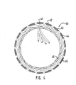
- Fig. 4 is an illustration showing the lapped winding structure in the motor of the invention;
- Fig. 5 is a diagram showing the demagnetization curves of a high energy product permanent magnet of the type used in the motor according to the invention;
- Fig. 6 shows the improved operating performance of a motor made in accordance to the invention as compared to a prior art motor with samarium-cobalt magnets having a comparable size; and
- Figs. 7A to 7D are a series of illustrations showing the method for forming the winding for the motor.
- The general structure of the motor according to the invention is shown in Figures 1 to 3.
- The motor includes a steel shaft 10 (Figs. 2A and 2B) surrounded by a
cylindrical iron sleeve 12 which provides the back iron for the rotor. Six permanent magnets 14-19 are mounted onsleeve 12 extending radially and are magnetized to provide alternating north and south poles, as shown in Fig. 1. The magnets 14-19 are high energy product magnets with energy products in excess of 26 MGOe (MegaGauss Oersteds) and preferably in excess of 30 MGOe. Suitable permanent magnets are those made from neodymium, iron and boron (NEOMAX-30H 0). The magnets are pressed arcuate shaped magnets and are mounted on theback iron sleeve 12 surroundingshaft 10. - A banding 20 surrounds the rotor structure to hold the magnets in place under high speed centrifugal force conditions. Banding is accomplished using high strength Kevlar filaments which are dipped in epoxy and then wound around the rotor including one or more helical layers followed by several hooped layers.
- The rotor can be constructed using six magnets each extending the full length of the rotor, or the magnets can be segmented as shown in Fig. 2A. An advantage to the segmented magnets is that a single motor design can produce motors of different horsepower ratings by simply changing the motor length and the number of magnet segments.
- The stator structure includes a cylindrical
outer shell 30 of laminated silicon steel which provides the outer back iron for the motor. The laminations are assembled and then cast in an aluminumouter housing 32. The individual laminations can include one or more notches on the inner diameter and can be assembled to randomly distribute the notches on the inner cylindrical surface to provide a better bond with the motor windings. Thewindings 40 are formed and then mounted inside the cylindricalback iron shell 30. The stator structure is slotless and, hence, thewindings 40 are located in the motor air gap between the permanent magnets of the rotor and the outer back iron shell. Since there are no teeth in the stator, the entire inner cylindrical surface can be used by the copper of the windings. If desired, small notches can be randomly located in the internal circumference of the laminations for better bonding to the winding against torque forces produced in the motor. - The motor in the illustrative embodiment is a six pole three phase winding and, therefore, includes eighteen (18) coils in the winding. The coils are pre-formed and then placed in a lapped configuration as shown in Fig. 4. The coils of one phase are shaded in the illustration to show the relative orientation of the coils. A coil 41 of phase A is followed by a
coil 42 of phase B which, in turn, is followed by acoil 43 of phase C, and then the sequence repeats. Thelongitudinal conductors 44 of one side of a coil are on the outside of the winding whereas thelongitudinal conductors 45 of the other side of the same coil are on the inside of the winding beneath theconductors 46 of the next coil of the same phase. The coils are lapped in this fashion to provide a balanced three-phase six pole winding 40. - The winding 40 is formed on a temporary cylindrical support 50 (Fig. 7) which is of a constant diameter starting from one end (to the left of Fig. 7A) and includes a reduced
diameter portion 52 at the other end. Afiberglass sleeve 54 is placed surrounding the winding support 50 (Fig. 7A) and the preformed coils 40 are then placed in position surrounding the sleeve 50 (Fig. 7B). When the coils are in place, the end turns 48 at one end of the winding tend to flare inwardly as permitted by the reduceddiameter portion 52 of thesupport 50, whereas the end turns 49 at the other end of the winding flare outwardly. The winding thus formed is then inserted into thestator structure support 50 can be removed from the outwardly flared end leaving thefiberglass sleeve 54 in place as part of the final stator structure. - With the method described, it is important that the preformed winding includes inwardly flared end turns at one end and outwardly flared end turns at the other end. The inwardly flared end turns permit insertion of the preformed winding into the cylindrical stator shell. The outwardly flared end turns permit removal of the support after the winding is in place in the stator shell. When the winding is in place, it is impregnated with a suitable resin material to provide a rigid winding structure bonded to the back iron and housing of the stator shell.
- The resin material must be carefully selected for the motor of this invention. It must have a high flexural strength in order to rigidify the winding since any freedom of movement adversely affects the ability of the winding to produce torque. A flexural strength of at least 140 kg/cm2 at 250°C, and preferably 280 kgfcm2 at 250°C is required. The motor is designed for continuous operation at 150°C and must be capable of withstanding peak temperatures of over 200°C. The thermal expansion of the resin must, therefore, be equal to or somewhat greater than the thermal expansion of the surrounding materials. The thermal coefficients of expansion for silicon steel, copper and aluminum are 10.8 x 10⁻⁵, 16.8 x 10⁻⁶ and 23 X 10-6 per °C, respectively. For these materials, the coefficient of thermal expansion for the resin should be in the range of 23 to 30 x 10-6/°C. The rating of the motor depends largely on the ability to dissipate heat from the windings and, therefore, the resin must also provide good thermal conductivity, preferably in the range above 6(cal)(cm)/(sec)(cm2)(°C). This is particularly true with the compact motor design resulting from the invention. Ceramic fillers are preferably incorporated in the resin to improve thermal conductivity. However, the ceramic fillers must be non-conductive and non-magnetic in order to avoid eddy current and iron losses. Furthermore, the resin must have a low viscosity below 50 000 cps in the uncured state in order to properly impregnate the winding.
- A suitable thermally conductive resin is StycastO 2762 epoxy resin. The typical properties for this resin are as follows:
-


- Dielectric DissipationWhen the winding is in place in the cylindrical outer shell of the stator, the epoxy is forced into the winding cavity at one end under pressure and is drawn through the winding by means of a vacuum applied at the other end. When the epoxy cures the winding becomes rigid and is securely bonded to the stator laminations. The ends of the winding cavity preferably flare out at both ends in the region of-the end turns to increase the surface area. The end surfaces can be machined to provide a flat surface for good thermal contact with the end bells of the motor (not shown). In most cases, however, good thermal contact between the resin and the

aluminum housing 32 will provide adequate heat dissipation. The demagnetization curves of a suitable magnet material, for example NEOMAX-30H@, are shown in Fig. 5. For temperatures beldw 100°C the properties are substantially linear and, hence, no demagnetization is likely to occur when operating in this temperature range. At elevated temperatures above 100°C, however, there is a "knee" in the curve which, at 140°C, occurs at Bd = 3 500 Gauss and Hb = 6 000 Oersted. The rapid falloff of the coercivity at field strengths higher than 6 000 Oersteds can cause significant demagnetization of the magnets. - The permeance P is the operating slope of the magnet in a given circuit. The slope is given by

- Lg is the length of the magnetic gap;
- Am is the area of magnet; and Ag is the area of gap.
- The allowable demagnetization field Ha is given by a line having slope P and passing through (Hd, Bd) at the knee in the curve. This can be written as

- Substituting for P and simplifying the equation becomes

- Thus, the maximum allowable demagnetization field Ha can be calculated for a given demagnetization characteristic and operating permeance P.
- For design comparison purposes, the worst case demagnetization field is when the stator currents are arranged such that the stator MMF directly opposes the magnet MMF. This is a realistic case since many servos are braked by shorting phase leads together, thus giving such a field alignment Current in phase A is peak and current in phases B and C is 1/2 the peak current value. By symmetry, the armature H field is radial at the centreline of the magnet Taking this path, the enclosed ampere turns per pole is

- From Ampere's law

- Thus, for a given combination of poles, gap length, magnet 20 Solving equation (2) for [peak and setting the allowable length, conductors, and current, the applied demagnetization applied demagnetization field Ha equal to the applied field field H can be calculated. H, gives

- Substituting equation (1) for H gives

- The various parameters of equation (3) for the conventional slotted design and the air gap winding design of the invention, both using the NdFeB magnet material shown in Fig. 5 with (Hd, Bd) of (6000, 3500) are as follows:

- As can be seen from Table I. the air gap winding design allows more than 3 1/2 times the peak torque allowed by the cinventional slotted design. With a maximum of 34.8A RMS current before demagnetization, the conventionai slotted design does not offer the needed peak torque for a nigh response servo motor.
- If the air gap is made relatively large, such as 0.3 inches in the illustrative embodiment of the invention, the reluctance of the magnetic path for flux generated in the stator is sufficiently high such that the flux, as seen by the magnets, remains below the level at which demagnetization is likely to occur. The ratio of the air gap length (Lg) to the magnet length (Lm), Fig. 1, must be in the range between 0.5 and 2.0. The use of permeances in the range of 4 to 6, common in slotted motor structures, is undesirable since it results in either an excessively large amount of expensive permanent magnet material or a small air gap inadequate to hold the desired number of windings required for a high performance motor.
- The ratio of the interpolar distance (Lip) to the radial gap length (Lg), as seen in Fig. 1, should be greater than 1.3. With high energy product magnets this ratio becomes important since a lower ratio results in ineffective use of the expensive permanent magnet materials due to increasingly high leakage flux.
- Figure 6 is a diagram illustrating the dynamic comparison of two motors with approximately the same outside physical dimensions.
Curves curves - Although only one illustrative embodiment of the invention has been described in detail, there are numerous variations within the scope of this invention.
Claims (19)
Applications Claiming Priority (2)
| Application Number | Priority Date | Filing Date | Title |
|---|---|---|---|
| US06/709,763 US4679313A (en) | 1985-03-08 | 1985-03-08 | Method of making a servo motor with high energy product magnets |
| US709763 | 1985-03-08 |
Publications (3)
| Publication Number | Publication Date |
|---|---|
| EP0193929A2 true EP0193929A2 (en) | 1986-09-10 |
| EP0193929A3 EP0193929A3 (en) | 1987-07-01 |
| EP0193929B1 EP0193929B1 (en) | 1990-06-13 |
Family
ID=24851225
Family Applications (1)
| Application Number | Title | Priority Date | Filing Date |
|---|---|---|---|
| EP86102832A Expired - Lifetime EP0193929B1 (en) | 1985-03-08 | 1986-03-04 | Method for making a servomotor |
Country Status (6)
| Country | Link |
|---|---|
| US (1) | US4679313A (en) |
| EP (1) | EP0193929B1 (en) |
| JP (2) | JP2554859B2 (en) |
| KR (1) | KR940008412B1 (en) |
| DE (2) | DE3672040D1 (en) |
| GB (1) | GB2172149B (en) |
Cited By (11)
| Publication number | Priority date | Publication date | Assignee | Title |
|---|---|---|---|---|
| EP0282876A3 (en) * | 1987-03-19 | 1989-05-17 | Kollmorgen Corporation | Method for winding the coils for an air gap motor method for winding the coils for an air gap motor |
| EP0336078A1 (en) * | 1988-02-29 | 1989-10-11 | Siemens Aktiengesellschaft | Apparatus for the measurement of the rotational speed and the position of a rotor of an electric machine |
| EP0461183A4 (en) * | 1989-02-28 | 1991-10-07 | Du Pont | Stator assembly for a non-static cogging brushless dc motor and method of fabricating the same. |
| US5265323A (en) * | 1989-02-28 | 1993-11-30 | E. I. Du Pont De Nemours And Company | Method of fabricating a stator assembly for a non-static cogging brushless DC motor |
| WO1993026075A1 (en) * | 1992-06-11 | 1993-12-23 | University Of Technology, Sydney | An electric motor and method of manufacture |
| WO1994009551A1 (en) * | 1992-10-09 | 1994-04-28 | Wolfgang Hill | Permanently excited electric machine with hard-magnetic and soft-magnetic segments |
| WO1994028612A1 (en) * | 1993-05-26 | 1994-12-08 | Atlas Copco Tools Ab | Stator for an electric machine |
| EP0795951A1 (en) * | 1996-03-11 | 1997-09-17 | Kollmorgen Corporation | Flip-chip layout input and verification apparatus and method |
| EP2597757A1 (en) * | 2011-11-24 | 2013-05-29 | Maxon Motor AG | Electric engine for high temperature applications |
| EP2017944B2 (en) † | 2007-07-13 | 2014-07-16 | Dr. Fritz Faulhaber GmbH & Co. KG | Electric miniature drive and inference element and production method for same |
| EP2882078A1 (en) * | 2013-12-05 | 2015-06-10 | Siemens Aktiengesellschaft | Electrical machine with a permanent magnet and a coil |
Families Citing this family (44)
| Publication number | Priority date | Publication date | Assignee | Title |
|---|---|---|---|---|
| US4933581A (en) * | 1987-10-01 | 1990-06-12 | Adalet/Scott Fetzer Company | Large air gap motor with rotor heat shield |
| CH675331A5 (en) * | 1987-10-21 | 1990-09-14 | Mavilor Syst Sa | |
| US5345669A (en) * | 1988-06-08 | 1994-09-13 | General Electric Company | Method of making a permanent magnet rotor |
| US5040286A (en) * | 1988-06-08 | 1991-08-20 | General Electric Company | Method for making permanent magnet rotor |
| US5237737A (en) * | 1988-06-08 | 1993-08-24 | General Electric Company | Method of making a permanent magnet rotor |
| US5144735A (en) * | 1988-06-08 | 1992-09-08 | General Electric Company | Apparatus for assembling a permanent magnet rotor |
| US5563463A (en) * | 1988-06-08 | 1996-10-08 | General Electric Company | Permanent magnet rotor |
| JPH069578Y2 (en) * | 1989-08-29 | 1994-03-09 | マブチモーター株式会社 | Field magnet for small motors |
| US5185543A (en) * | 1990-02-27 | 1993-02-09 | Fichtel & Sachs Ag | Motor vehicle drive line torsional vibration damper |
| US5606791A (en) * | 1993-09-17 | 1997-03-04 | Fougere; Richard J. | Method of making a slotless electric motor or transducer |
| DE4423620A1 (en) | 1994-07-06 | 1996-01-11 | Philips Patentverwaltung | Electric motor excitable by means of permanent magnets, in particular internal rotor or external rotor motor |
| DE4438132A1 (en) † | 1994-10-27 | 1996-05-02 | Wilo Gmbh | Canned pump |
| US6208056B1 (en) * | 1997-09-08 | 2001-03-27 | Active Power, Inc. | Cartridge armatures for electro-dynamic machines |
| US6362554B1 (en) * | 1999-07-29 | 2002-03-26 | Encap Motor Corporation | Stator assembly |
| US6617721B1 (en) | 1999-07-29 | 2003-09-09 | Encap Motor Corporation | High speed spindle motor |
| US6753628B1 (en) | 1999-07-29 | 2004-06-22 | Encap Motor Corporation | High speed spindle motor for disc drive |
| US6437464B1 (en) | 1999-07-29 | 2002-08-20 | Encap Motor Corporation | Motor and disc assembly for computer hard drive |
| US6300695B1 (en) | 1999-07-29 | 2001-10-09 | Encap Motor Corporation | High speed spindle motor with hydrodynamic bearings |
| US6501616B1 (en) | 1999-07-29 | 2002-12-31 | Encap Motor Corporation | Hard disc drive with base incorporating a spindle motor stator |
| WO2001045233A1 (en) * | 1999-12-17 | 2001-06-21 | Encap Motor Corporation | Spindle motor with encapsulated stator and method of making same |
| US6531794B1 (en) * | 2000-07-20 | 2003-03-11 | General Electric Company | Method for fabricating motors of different outputs using standardized parts |
| WO2002015229A1 (en) * | 2000-08-10 | 2002-02-21 | John Floresta | High performance slotless electric motor and method for making same |
| DE10058669B4 (en) * | 2000-11-25 | 2004-05-06 | Impella Cardiotechnik Ag | micromotor |
| US6892439B1 (en) | 2001-02-01 | 2005-05-17 | Encap Motor Corporation | Motor with stator made from linear core preform |
| US7036207B2 (en) * | 2001-03-02 | 2006-05-02 | Encap Motor Corporation | Stator assembly made from a plurality of toroidal core segments and motor using same |
| DE10224776A1 (en) | 2002-06-04 | 2004-03-11 | Magnet-Motor Gesellschaft Für Magnetmotorische Technik Mbh | Electrical machine |
| US7042122B1 (en) * | 2002-08-02 | 2006-05-09 | James Dufala | Electric motor |
| US20050093392A1 (en) * | 2003-10-31 | 2005-05-05 | Medtronic, Inc. | Electric motor having nanocrystalline alloy component for use in surgical procedure |
| US20050116578A1 (en) * | 2003-11-01 | 2005-06-02 | Medtronic, Inc. | Small hand-held medical drill |
| US20070138891A1 (en) * | 2005-12-19 | 2007-06-21 | Emerson Electric Co. | Magnet retention and positioning sleeve for surface mounted rotor assemblies |
| DE102006027001A1 (en) * | 2006-06-08 | 2007-12-13 | Oase Gmbh | Water pump for especially ponds, aquariums, fountains and the like |
| JP2008285377A (en) * | 2007-05-18 | 2008-11-27 | Panasonic Corp | Bonding optical element |
| US20100045121A1 (en) * | 2007-10-22 | 2010-02-25 | Roopnarine | Motor for high temperature applications |
| US8358043B2 (en) * | 2008-10-24 | 2013-01-22 | Baker Hughes Incorporated | Enhanced thermal conductivity material in annular gap between electrical motor stator and housing |
| US20110062805A1 (en) * | 2009-09-17 | 2011-03-17 | Caterpillar Inc. | Switched reluctance machine with eddy current loss dampener |
| CN101951080B (en) * | 2010-08-03 | 2012-10-03 | 浙江山风汽车空调有限公司 | Direct-current brush motor coil magnet positioning device and method thereof |
| EA016623B1 (en) * | 2011-06-16 | 2012-06-29 | Открытое Акционерное Общество "Нпо "Русский Электропривод" | Method of electrical machine with permanent magnets assembly |
| DE102011115412A1 (en) | 2011-10-08 | 2012-05-03 | Daimler Ag | Method for removing functional layer formed on surface of component e.g. stator used in electromotor, involves focusing laser beam on the functional layer so as to remove the functional layer |
| US20150333584A1 (en) * | 2014-05-15 | 2015-11-19 | Calnetix Technologies, Llc | High speed brushless dc electric machine |
| EP4233162A4 (en) * | 2020-10-20 | 2024-10-30 | Christopher W. Gabrys | ELECTRIC ROTATING MACHINE WITHOUT NOTCHES |
| EP4145682A1 (en) | 2021-09-03 | 2023-03-08 | SKF Magnetic Mechatronics | Rotary electrical machine and stator assembly for such machine |
| EP4145681A1 (en) * | 2021-09-03 | 2023-03-08 | SKF Magnetic Mechatronics | Rotary electrical machine and stator assembly for such machine |
| EP4145680A1 (en) * | 2021-09-03 | 2023-03-08 | Skf Magnetic Mechatronics | Rotary electrical machine and rotor for such machine |
| WO2025188315A1 (en) * | 2024-03-08 | 2025-09-12 | Khandan Barani Mohammad | Slotless electric motor and means of making the same |
Family Cites Families (26)
| Publication number | Priority date | Publication date | Assignee | Title |
|---|---|---|---|---|
| US1875207A (en) * | 1930-12-11 | 1932-08-30 | Vincent G Apple | Alternating current motor |
| US2749456A (en) * | 1952-06-23 | 1956-06-05 | Us Electrical Motors Inc | Waterproof stator construction for submersible dynamo-electric machine |
| US2759116A (en) * | 1954-11-26 | 1956-08-14 | John P Glass | Induction type tachometer |
| CH347571A (en) * | 1955-09-26 | 1960-07-15 | Parsons & Co Ltd C A | Dynamo-electric machine |
| DE1021466B (en) * | 1956-11-02 | 1957-12-27 | Christian Dunker | Manufacture of ironless runners, especially bell-shaped runners, for small electric motors and generators |
| GB994548A (en) * | 1964-03-06 | 1965-06-10 | Franklin Electric Co Inc | A frame for a submersible electric motor |
| DE1563002A1 (en) * | 1966-07-23 | 1970-03-19 | Siemens Ag | Commutator and slip ringless DC motor |
| GB1330674A (en) * | 1970-09-24 | 1973-09-19 | Siemens Ag | Electrical motor |
| US3827141A (en) * | 1972-05-17 | 1974-08-06 | Skf Ind Trading & Dev | Method of manufacturing an electric rotary machine |
| US3841133A (en) * | 1973-08-13 | 1974-10-15 | Westinghouse Electric Corp | Apparatus and method for shaping end turns of coils in dynamo-electric machine cores |
| US3963950A (en) * | 1973-10-17 | 1976-06-15 | Hitachi, Ltd. | Stator of rotary electric machine |
| US3892034A (en) * | 1974-02-26 | 1975-07-01 | Mikhail Alexandrovich Arakelov | Method of assembling slotless stator of electrical machine |
| CA1004274A (en) * | 1974-04-04 | 1977-01-25 | Canadian General Electric Company Limited | Permanent magnet hermetic synchronous motor |
| JPS5147205A (en) * | 1974-10-21 | 1976-04-22 | Sony Corp | Mootano suteetano seiho |
| DE2460964C3 (en) * | 1974-12-21 | 1984-02-09 | Hanning Elektro-Werke Gmbh & Co, 4800 Bielefeld | Method for pulling the stator winding composed of coil strands into the slots of the laminated stator core of an internal rotor electric motor |
| CH604411A5 (en) * | 1975-12-08 | 1978-09-15 | Papst Motoren Kg | Brushless DC motor with permanent magnet rotor |
| JPS5931304B2 (en) * | 1976-08-11 | 1984-08-01 | セイコーインスツルメンツ株式会社 | brushless motor |
| GB1604121A (en) * | 1977-04-08 | 1981-12-02 | Sony Corp | Dc motors |
| JPS5441408A (en) * | 1977-09-07 | 1979-04-02 | Seiko Epson Corp | Transducer for electronic watch |
| JPS55120658A (en) * | 1979-03-13 | 1980-09-17 | Toray Silicone Co Ltd | Silicone composition forming ceramic at high temperature |
| JPS55160957A (en) * | 1979-05-31 | 1980-12-15 | Matsushita Electric Ind Co Ltd | Manufacture of cup-type coreless electric machine |
| JPS5686059A (en) * | 1979-12-17 | 1981-07-13 | Mitsubishi Electric Corp | Manufacture of stator |
| IT1128041B (en) * | 1980-02-11 | 1986-05-28 | Pavesi Spa Off Mec | DEVICE AND PROCEDURE FOR THE INSERTION OF PRE-WINDED MASSES IN THE STATOR GROOVES OF DYNAMOELECTRIC MACHINES |
| JPS5835024A (en) * | 1981-08-26 | 1983-03-01 | Sumitomo Metal Ind Ltd | Manufacture of flange with drum |
| FR2514582A1 (en) * | 1981-10-08 | 1983-04-15 | Artus | BRUSHLESS ELECTRIC MICROMOTOR |
| JPS5996843A (en) * | 1982-11-19 | 1984-06-04 | Hitachi Ltd | Stator for underwater motor and manufacture thereof |
-
1985
- 1985-03-08 US US06/709,763 patent/US4679313A/en not_active Expired - Lifetime
-
1986
- 1986-03-04 EP EP86102832A patent/EP0193929B1/en not_active Expired - Lifetime
- 1986-03-04 DE DE8686102832T patent/DE3672040D1/en not_active Expired - Lifetime
- 1986-03-06 GB GB8605593A patent/GB2172149B/en not_active Expired
- 1986-03-06 DE DE19863607648 patent/DE3607648A1/en active Granted
- 1986-03-07 JP JP61051277A patent/JP2554859B2/en not_active Expired - Lifetime
- 1986-03-08 KR KR1019860001638A patent/KR940008412B1/en not_active Expired - Lifetime
-
1996
- 1996-02-15 JP JP8054244A patent/JP2762257B2/en not_active Expired - Lifetime
Cited By (15)
| Publication number | Priority date | Publication date | Assignee | Title |
|---|---|---|---|---|
| EP0282876A3 (en) * | 1987-03-19 | 1989-05-17 | Kollmorgen Corporation | Method for winding the coils for an air gap motor method for winding the coils for an air gap motor |
| EP0336078A1 (en) * | 1988-02-29 | 1989-10-11 | Siemens Aktiengesellschaft | Apparatus for the measurement of the rotational speed and the position of a rotor of an electric machine |
| US4897603A (en) * | 1988-02-29 | 1990-01-30 | Siemens Aktiengesellschaft | Arrangement for determining the speed and rotor position of an electric machine |
| EP0461183A4 (en) * | 1989-02-28 | 1991-10-07 | Du Pont | Stator assembly for a non-static cogging brushless dc motor and method of fabricating the same. |
| US5265323A (en) * | 1989-02-28 | 1993-11-30 | E. I. Du Pont De Nemours And Company | Method of fabricating a stator assembly for a non-static cogging brushless DC motor |
| WO1993026075A1 (en) * | 1992-06-11 | 1993-12-23 | University Of Technology, Sydney | An electric motor and method of manufacture |
| WO1994009551A1 (en) * | 1992-10-09 | 1994-04-28 | Wolfgang Hill | Permanently excited electric machine with hard-magnetic and soft-magnetic segments |
| WO1994028612A1 (en) * | 1993-05-26 | 1994-12-08 | Atlas Copco Tools Ab | Stator for an electric machine |
| US5714827A (en) * | 1993-05-26 | 1998-02-03 | Atlas Copco Tools Ab | Stator for an electric machine |
| US6034463A (en) * | 1993-05-26 | 2000-03-07 | Atlas Copco Tools Ab | Stator for an electric machine |
| EP0795951A1 (en) * | 1996-03-11 | 1997-09-17 | Kollmorgen Corporation | Flip-chip layout input and verification apparatus and method |
| EP2017944B2 (en) † | 2007-07-13 | 2014-07-16 | Dr. Fritz Faulhaber GmbH & Co. KG | Electric miniature drive and inference element and production method for same |
| EP2597757A1 (en) * | 2011-11-24 | 2013-05-29 | Maxon Motor AG | Electric engine for high temperature applications |
| US8946962B2 (en) | 2011-11-24 | 2015-02-03 | Maxon Motor Ag | Electric motor for high-temperature applications |
| EP2882078A1 (en) * | 2013-12-05 | 2015-06-10 | Siemens Aktiengesellschaft | Electrical machine with a permanent magnet and a coil |
Also Published As
| Publication number | Publication date |
|---|---|
| JPH08242566A (en) | 1996-09-17 |
| EP0193929A3 (en) | 1987-07-01 |
| JP2554859B2 (en) | 1996-11-20 |
| KR860007767A (en) | 1986-10-17 |
| GB8605593D0 (en) | 1986-04-09 |
| JP2762257B2 (en) | 1998-06-04 |
| JPS61251466A (en) | 1986-11-08 |
| DE3672040D1 (en) | 1990-07-19 |
| GB2172149B (en) | 1989-06-28 |
| KR940008412B1 (en) | 1994-09-14 |
| DE3607648A1 (en) | 1986-09-18 |
| EP0193929B1 (en) | 1990-06-13 |
| US4679313A (en) | 1987-07-14 |
| DE3607648C2 (en) | 1990-03-22 |
| GB2172149A (en) | 1986-09-10 |
Similar Documents
| Publication | Publication Date | Title |
|---|---|---|
| EP0193929B1 (en) | Method for making a servomotor | |
| US4954739A (en) | Servo motor with high energy product magnets | |
| US4868970A (en) | Method of making an electric motor | |
| US4709180A (en) | Toothless stator construction for electrical machines | |
| US6300702B1 (en) | Electrical machine element | |
| US7247967B2 (en) | Electric motor having a stator | |
| US7737598B2 (en) | Electric motor having a stator | |
| EP0620952B1 (en) | Lightweight high power electromotive device | |
| US4605874A (en) | Brushless D.C. dynamoelectric machine having ferrite material magnetic circuit | |
| US4625392A (en) | Method of manufacturing a molded rotatable assembly for dynamoelectric machines | |
| US4852245A (en) | Toothless stator electrical machine construction method | |
| US4427910A (en) | Magnetic slot wedge with low average permeability and high mechanical strength | |
| US7640648B1 (en) | Method of fabricating a magnetic flux channel for a transverse wound motor | |
| US4843269A (en) | Large air gap motor | |
| WO2002015229A9 (en) | High performance slotless electric motor and method for making same | |
| CA2109821A1 (en) | Electrical machines | |
| US3320454A (en) | Alternating current generator | |
| WO2001047089A2 (en) | Electronically commutated electrical machine | |
| US4933581A (en) | Large air gap motor with rotor heat shield | |
| WO1991001585A1 (en) | Toothless stator construction for electrical machines | |
| US6768244B2 (en) | Stator, dynamoelectric machine, and methods for fabricating same | |
| US20080093950A1 (en) | Polyphase Claw-Pole Machines With a Segmented Magnetic Circuit | |
| CA3132583A1 (en) | Permanent magnet assisted synchronous reluctance machine | |
| JP2881314B2 (en) | Permanent magnet field type motor | |
| US3465186A (en) | Dynamoelectric machine and methods of manufacturing armature assemblies therefor |
Legal Events
| Date | Code | Title | Description |
|---|---|---|---|
| PUAI | Public reference made under article 153(3) epc to a published international application that has entered the european phase |
Free format text: ORIGINAL CODE: 0009012 |
|
| AK | Designated contracting states |
Kind code of ref document: A2 Designated state(s): CH DE FR GB IT LI SE |
|
| 17P | Request for examination filed |
Effective date: 19870219 |
|
| PUAL | Search report despatched |
Free format text: ORIGINAL CODE: 0009013 |
|
| AK | Designated contracting states |
Kind code of ref document: A3 Designated state(s): CH DE FR GB IT LI SE |
|
| 17Q | First examination report despatched |
Effective date: 19880725 |
|
| ITF | It: translation for a ep patent filed | ||
| RAP1 | Party data changed (applicant data changed or rights of an application transferred) |
Owner name: KOLLMORGEN CORPORATION |
|
| GRAA | (expected) grant |
Free format text: ORIGINAL CODE: 0009210 |
|
| AK | Designated contracting states |
Kind code of ref document: B1 Designated state(s): CH DE FR GB IT LI SE |
|
| REF | Corresponds to: |
Ref document number: 3672040 Country of ref document: DE Date of ref document: 19900719 |
|
| ET | Fr: translation filed | ||
| PLBE | No opposition filed within time limit |
Free format text: ORIGINAL CODE: 0009261 |
|
| STAA | Information on the status of an ep patent application or granted ep patent |
Free format text: STATUS: NO OPPOSITION FILED WITHIN TIME LIMIT |
|
| 26N | No opposition filed | ||
| ITTA | It: last paid annual fee | ||
| EAL | Se: european patent in force in sweden |
Ref document number: 86102832.2 |
|
| REG | Reference to a national code |
Ref country code: GB Ref legal event code: IF02 |
|
| PGFP | Annual fee paid to national office [announced via postgrant information from national office to epo] |
Ref country code: GB Payment date: 20050223 Year of fee payment: 20 |
|
| PGFP | Annual fee paid to national office [announced via postgrant information from national office to epo] |
Ref country code: FR Payment date: 20050318 Year of fee payment: 20 |
|
| PGFP | Annual fee paid to national office [announced via postgrant information from national office to epo] |
Ref country code: SE Payment date: 20050323 Year of fee payment: 20 Ref country code: CH Payment date: 20050323 Year of fee payment: 20 |
|
| PGFP | Annual fee paid to national office [announced via postgrant information from national office to epo] |
Ref country code: IT Payment date: 20050330 Year of fee payment: 20 |
|
| PGFP | Annual fee paid to national office [announced via postgrant information from national office to epo] |
Ref country code: DE Payment date: 20050502 Year of fee payment: 20 |
|
| PG25 | Lapsed in a contracting state [announced via postgrant information from national office to epo] |
Ref country code: GB Free format text: LAPSE BECAUSE OF EXPIRATION OF PROTECTION Effective date: 20060303 |
|
| REG | Reference to a national code |
Ref country code: GB Ref legal event code: PE20 |
|
| REG | Reference to a national code |
Ref country code: CH Ref legal event code: PL |
|
| EUG | Se: european patent has lapsed |