EP0193448A1 - Statische Auslöseeinheit für Leistungsschalter mit parallel zu einer analogen Verarbeitungskette wirkender numerischer Verarbeitungskette - Google Patents
Statische Auslöseeinheit für Leistungsschalter mit parallel zu einer analogen Verarbeitungskette wirkender numerischer Verarbeitungskette Download PDFInfo
- Publication number
- EP0193448A1 EP0193448A1 EP86400284A EP86400284A EP0193448A1 EP 0193448 A1 EP0193448 A1 EP 0193448A1 EP 86400284 A EP86400284 A EP 86400284A EP 86400284 A EP86400284 A EP 86400284A EP 0193448 A1 EP0193448 A1 EP 0193448A1
- Authority
- EP
- European Patent Office
- Prior art keywords
- analog
- threshold
- digital
- value
- trigger
- Prior art date
- Legal status (The legal status is an assumption and is not a legal conclusion. Google has not performed a legal analysis and makes no representation as to the accuracy of the status listed.)
- Granted
Links
Images


Classifications
-
- H—ELECTRICITY
- H02—GENERATION; CONVERSION OR DISTRIBUTION OF ELECTRIC POWER
- H02H—EMERGENCY PROTECTIVE CIRCUIT ARRANGEMENTS
- H02H3/00—Emergency protective circuit arrangements for automatic disconnection directly responsive to an undesired change from normal electric working condition with or without subsequent reconnection ; integrated protection
- H02H3/08—Emergency protective circuit arrangements for automatic disconnection directly responsive to an undesired change from normal electric working condition with or without subsequent reconnection ; integrated protection responsive to excess current
- H02H3/093—Emergency protective circuit arrangements for automatic disconnection directly responsive to an undesired change from normal electric working condition with or without subsequent reconnection ; integrated protection responsive to excess current with timing means
- H02H3/0935—Emergency protective circuit arrangements for automatic disconnection directly responsive to an undesired change from normal electric working condition with or without subsequent reconnection ; integrated protection responsive to excess current with timing means the timing being determined by numerical means
Definitions
- the present invention aims to achieve a digital trigger having the advantages of analog systems.
- the trigger according to the invention is characterized in that said analog signal is applied in parallel to the digital processing assembly to an analog processing assembly, arranged to issue an instantaneous trigger command when a threshold is exceeded, said order being transmitted to said triggering means
- the analog system makes use of the sensors and the triggering relay of the digital trigger, only the digital processing chain being shunted by the analog processing chain, the latter being active for certain instantaneous trips. This duplication is a safety and reliability factor for the trigger.
- the intervention threshold of the analog system is lowered during the put-in-route period, so as to replace digital processing for the instantaneous tripping function. This simultaneously protects the installation and the circuit breaker.
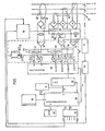
- an electrical distribution network with four conductors RSTN for supplying a load comprises a circuit breaker 10 capable of interrupting the circuit in the open position.
- the mechanism 12 of the circuit breaker 10 is controlled by a polarized relay 14, for controlling the tripping of the circuit breaker in the event of an overload, short-circuit or earth fault.
- Each phase conductor RST is associated with a current transformer 16, which delivers a signal proportional to the current flowing through the associated conductor, the signal being applied to a rectifier bridge 18, at full alternation.
- the outputs of the three rectifier bridges 18 are connected in series in a circuit, comprising in series a resistor 20, a Zener diode 22 and a diode 24 to make appear at the terminals of the resistor 20 a voltage signal, proportional to the maximum value of the current flowing through the conductors RST and at the terminals of the diodes 22, 2 4 a supply voltage of the electronic circuits.
- the voltage signal is applied to the inputs of two amplifiers 26, 28 of different gains and the output of each amplifier 26, 28 is connected on the one hand to an input 1, 3 of a multiplexer 29 and on the other hand to a divider bridge 30, 32, the midpoint of which is connected to an input 2, 4 of the multiplexer 29.
- the assembly, amplifiers 26, 28 and divider bridges 30, 32 belongs to a calibration circuit 3 4 of the voltage signal, described in detail below and marked in broken lines in Figure 1.
- the calibration circuit 34 includes a third amplifier 36, which receives a signal generated by the summing transformer 38, the primary windings of which consist of the NRST conductors passing through a toroid, carrying a secondary winding 40 which delivers a signal in the event of a fault at Earth.
- the output of the amplifier 36 is connected to the input 5 of the multiplexer 29 and to a divider bridge 41, the midpoint of which is connected to input 6 of multiplexer 29.
- Inputs 1 to 6 are connected in parallel by diodes 44 to the emitter of a transistor 42 whose collector is grounded and whose base is biased by a predetermined voltage, by example of 5 Volts, corresponding to the maximum value applicable to the multiplexer 29.
- the multiplexer 29 receives signals representative of the phase current on the four inputs 1 to 4 and signals representative of the ground current on both inputs 5, 6. These signals, in particular those of earth fault, can of course be produced in a different way, for example from the signals delivered by the current transformers 16.
- the multiplexer 29 for example an ADC0808 multiplexer from the company National Semiconductor, is controlled by the address and control line 46 connected to the outputs 1 of a microprocessor 48. Depending on the address provided by the microprocessor 48 the signal from one of the inputs 1 - 6 of the multiplexer 29 is transmitted by the output S of the multiplexer 29 to an analog digital converter 50 with 8 bits.
- a bus 52 connects the output of the digital analog converter 50 to an input, output 2 of the microprocessor 48.
- a block 54 with eight multiplexed switches 72-86 is connected to the microprocessor 48, on the one hand by a connection to the bus 52 and on the other hand in 3 by an address link 56. Each switch 72-86 has eight distinct positions for adjusting the trigger parameters, described below.
- An output register 58 is connected to the microprocessor 48 by a 6-bit link 60 and a 1-bit link 62 for transmission on 7 output channels S1 to S7 of command and signaling orders.
- the output S1 is connected to the relay 1 4 to control the tripping of the circuit breaker 10, while the outputs S2 to S6 are connected to display means of a control panel 64, arranged on the front face of the circuit breaker, in particular of the trip unit containing all the fault trip circuits and components.
- the S7 output is connected to an analog trip command described below.
- a non-volatile ROM memory 66 is connected to a link 4 of the microprocessor 48 to provide it with the execution program as well as permanent data stored in the form of tables.
- the recorded program corresponds to the functions executed by the trigger.
- the same trigger can be designed for several ranges of functions and each range obviously corresponds to a particular program.
- the program chosen can be saved in the ROM memory during manufacture or according to a preferred embodiment, the different programs are saved in different memories, the trigger being personalized by the choice of the appropriate memory, during assembly.
- the easements, grouped in a block 68 connected to an input 5 of the microprocessor 48, include the circuits necessary for the operation of the microprocessor, in particular the clock for sequencing the sequence of instructions, the initialization circuits and the like.
- the microprocessor is for example the model MC 146805 sold by the company Motorola, which contains standard resources, such as the processing unit, the interfaces, the volatile RAM memories, the computing unit.
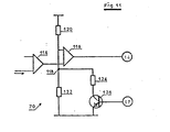
- Block 70 receives the analog phase signal at the output of the rectifier bridges 18.
- Block 70 compares this signal with a predetermined threshold value, in order to emit a tripping order transmitted to relay 14, when crossing the threshold as described in detail below.
- Block 70 provides a faster trigger speed than that of the digital trigger.
- FIG. 1 and the corresponding description contain the elements essential to the functioning of the trigger, the accessory elements of the analog and digital parts, such as the power supplies, the resistors and bias capacitors, the registers and memories of the fugitive signals, having been omitted so as not to unnecessarily overload the description.
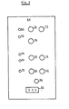
- the control panel 64 has eight switches 72-86 which are the eight switches of the block 54 illustrated in FIG. 1. Each eight-position switch cooperates with a resistive network to select one of the eight distinct values, transmitted to the microprocessor 48 during of the interrogation of block 54 .
- the panel 64 also has five light-emitting diodes or LEDs 90-98 and a connector 88 of a test block.
- the trip device according to the invention can be used for two types of function, a protection function against phase and earth fault and a protection function against phase fault and a load shedding function.
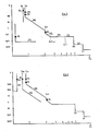
- FIG. 3 illustrates, on a logarithmic scale, the tripping curves of the phase and earth protection.
- the long delay threshold ILR that is to say the intensity of the current beyond which the long delay tripping cycle is initiated, is adjustable by the switch 80.
- the long delay time delay can be adjusted by switch 78 which modifies the constant T1 .
- the trigger starts a short delay trigger cycle, which anticipates the long delay trigger.
- the switch 84 performs the adjustment of the short delay ICR threshold and the switch 82 that of the constant short delay time delay T3.
- the transition from the constant-time characteristic to that of the inverse-time characteristic is fixed at a constant value of the current.
- a third threshold, IIN greater than the ICR threshold and adjustable by the switch 86, causes the instantaneous tripping cycle, whose timing T4 corresponds to the trigger response time which is not adjustable.
- the instantaneous analog trip device 70 intervenes in normal operation for an ultra-fast opening of the circuit breaker 10.
- an overload threshold ls appears, with an abscissa slightly lower than that of the long delay threshold ILR, the crossing of which signals the proximity of the long delay threshold and the risk of tripping.
- Switch 76 sets the overload threshold ls. This signal for crossing the threshold Is can be used for a communication simplified load shedding request,. in the event of interruption of a non-priority circuit. As soon as the current falls below the Is threshold, the output is deactivated and the unloaded circuit is reconnected.
- the earth protection representative curve includes an earth protection threshold IP and a time delay T5 at constant time.
- the IP threshold is adjustable by switch 74 and the timer T5 by switch 72.
- the status of the trip unit at a given time is displayed on the panel 64 by the light-emitting diodes or LEDs 90-98, represented on the curves of FIG. 3.
- the LED 90 represented by a solid circle on the earth protection threshold IP, is lit when a circuit breaker 10 trips on an earth fault. It remains on until the moment of an external intervention, for example of reset.
- the indicator 92 represented by four circular sectors alternately white and black, lights up when the overload threshold Is is crossed and goes off automatically as soon as the current becomes again below this threshold.
- the crossing of the long delay ILR threshold is signaled by the warning light 94, which goes out if the current value decreases below this threshold before the end of the time delay.
- a tripping on overload, controlled by the long delay circuit, is signaled by the warning light 96 while a short delay and instantaneous tripping causes the warning light 98 to light up.
- the extinction of the warning lights 96, 98 requires an external action.
- the adjustment precision can be increased by the use of switches 72-86 having a greater number of positions or according to a preferred mode by a combination of two adjustment means, more particularly of the switch 76 and of the other adjustment switches. Such a combination gives 6 4 adjustment notches, the switch 76 playing a double role, made possible by a sufficient difference between the thresholds fs and ILR. It is conceivable to add independent switches to achieve this type of combination.
- the same device can be used for another protection version, illustrated by the curves in FIG. 4.
- the phase protection tripping curve is identical to that illustrated in FIG. 3, but the earth protection is not not insured.
- the switches 72, 74 and the indicators 90, 92 associated with this function are available and the software is modified to provide a load shedding and shedding function illustrated by curves 106, 108.
- the load shedding threshold IDE lower than the long delay threshold ILR, is adjustable by switch 72, the light 90 signaling a load shedding operation.
- the IRE load shedding threshold which is different and lower than the IDE load shedding threshold, is adjustable by the switch 74 and indicated by the indicator 92.
- the load shedding curve 106 is in inverse time parallel to the long delay protection curve 100, while the Relestage curve 108 is at constant time The settings must always ensure load shedding before a long delay trip.
- the different protections and functions of the trip unit require current measurement with great dynamics.
- the number representing 0.4 ln must have at least the value 100, which is equivalent to a value of 3000 for the maximum intensity of 12 ln.
- the number 3000 requires 12-bit coding, but a 12-bit digital analog converter is slow and expensive.
- the calibration circuit 34 adapts the dynamics of the analog chain to that of the digital analog converter 50 to 8 bits while respecting the precision of 1%.
- the gain of amplifier 26 is chosen to transform an analog signal, corresponding to a maximum current of 14 In, applied to its input into a maximum signal, for example of 5 Volts, appearing on channel 2 of input of the multiplexer 29 which will be digitized by the value 256 at the output of the digital analog converter 50.
- the divider bridge 30, of a ratio 2 applies on channel 1 a double signal and the maximum value of 5 Volts is not exceeded as long as the analog signal at the input of amplifier 26 remains less than 7 ln.
- the amplifier 28 applies to the input 4 of the multiplexer 29 a maximum signal for a value of 1.7 In of the current and to the input 3 a maximum signal for a value of 0.85 ln. It is easy to see that the gain ratio of the amplifiers 26, 28 is 8.
- the microprocessor 48 selects one of the channels 1 to 4 according to the value of the current, in this case channel 2 for a current included between 7 and 14 ln, channel 1 for a current between 1.7 and 7 ln, channel 4 for a current between 0.85 and 1.7 ln, and channel 3 for a current less than 0.85 ln.
- the microprocessor 4 8 multiplies the digitization by a factor taking into account the selected channel, to restore the initial magnitude of the signal.
- the earth fault signal is likely to be applied to the 2 channels 5 and 6 only.
- the dynamic range of this signal is less than that of the phase fault and the two calibers are sufficient.
- the selection of the two channels 5, 6 by the microprocessor 48 is carried out in the manner described above, which it is unnecessary to recall.
- the transition from the analog channel to the digital channel results in a sampling of the processed signals.
- the value of the digital signal remains constant during the duration of the sample and this duration is determined by the sampling period fixed by the microprocessor 48. This duration, for example of 1.84 milliseconds, must be compared with the duration of 10 milliseconds of an alternation of the alternating signal and it is clear that the error introduced by the sampling is not negligible.
- the timing diagram according to FIG. 6a shows on the one hand the variation curve 110 of an analog signal rectified at full alternation, as a function of time and on the other hand, the curve 112 of the corresponding sample available at the output of the converter analog digital 50.
- the chronometric selectivity is achieved when the non-tripping time of the upstream circuit breaker is greater than the tripping time, that is to say the total breaking time of the downstream circuit breaker.
- the tripping and non-tripping curves, of the type illustrated in Figures 3 and 4, of circuit breakers in series, must be offset enough to avoid any intersection of these curves.
- the specialist is well aware of these problems of selectivity and the advantage of a difference as small as possible between the trigger and non-trigger times to interrupt the fault current as quickly as possible while maintaining the supply to the healthy parts of the 'installation.
- the precision of the sampled peak value is increased by blocking and memorizing the last peak and by processing this blocked value at the last peak to ensure the protection functions.
- MESURI which is the MEASUREMENT of the intensity of the sample treated at an instant t.
- MESURI-1 which is the MEASUREMENT of the intensity of the sample treated at an instant t-1.
- INTPHA which is the sampled value of the PHAse INTensity, blocked at the last peak.
- TEMPEC which is the ELAPSED TEMPs managed in countdown.
- FIG. 7. represents the flowchart of processing: At time t1 the microprocessor 48 calls and processes the sampled signal for measuring the intensity MESURI delivered by the digital analog converter 50 (fig. 6a). This MESURI signal is compared to the INTPHA signal (fig. 6d) of stored phase intensity, blocked at the last peak. If MESURI is greater than INTPHA the peak value is increasing and the value DERCRE (fig. 6b), which represents the value of the last peak less than the INTPHA signal, is set to zero.
- the MESURI value is stored in the MESURI-1 memory (fig. 6c) as well as in the INTPHA - memory (fig. 6d).
- the TEMPEC value (fig. 6e), which manages the countdown, is set to the maximum and the INTPHA value is processed by the microprocessor 48 in the aforementioned manner to ensure the protection functions.
- the measurements MESURI and MESURI-1 are compared. At time t2 the measurement MESURI is not greater than MESURI-1 and the value MESURI is entered in the memory MESURI-1. Then we check if TEMPEC is equal to zero, which is not the case at time t2 and we decrease TEMPEC.
- the INTPHA intensity is treated to ensure the protective function.
- the measurement MESURI is always less than the intensity INTPHA, but it is greater than MESURI-1 (increasing phase).
- the measurement MESURI is compared with the peak DERCRE and since MESURI is greater than DERCRE the value MESURI is entered into the memory before continuing the aforementioned program for introducing the value MESURI into the memory MESURI-1 and the other operations.
- the peak sampled value of the second half-wave is lower than that of the first half-wave and it is seen that the stored value INTPHA retained for the processing is the highest peak value.
- the two half-waves of the analog signal are identical, the difference of the peak sampled values resulting from the sampling.
- MESURI again exceeds INTPHA and in the manner described for the first alternation DERCRE is reset, MESURI replacing the value MESURI-1 and INTPHA in the memory.
- TEMPEC is reset to the maximum value and the new peak sampled value INTPHA is blocked.
- the processed value, stored in INTPHA corresponds to the sampled value blocked at the last peak, the countdown being restarted at each again exceeding the peak value.
- This value takes into account blocked at least two peak values for an alternating current of 50 Hz, the duration of each cycle is 1 0 milliseconds. If during the 22 milliseconds the peak values remain lower than the blocked peak value INTPHA, the latter is replaced by the value DERCRE which is the last blocked peak value less than INTPHA. When the peak values grow, the signal processed immediately takes this increase into account, while at the decrease there is a 22 millisecond delay.
- Locking at the last peak has no influence on instantaneous triggering, but for short delay and long delay triggering it allows a reduction of the sampling error.
- the 22 millisecond delay can cause an unjustified trigger, but the influence is weak considering the delays of the order of one second of such triggers.
- the 22 milliseconds are a compromise between greater precision on the peak value and as small a difference as possible between the trigger and non-trigger time It is clear that the delay can be increased to include a greater number of alternations and thus increasing the accuracy, especially when measuring or displaying the peak value independently of the circuit breaker control.
- the method of blocking at the last peak has been described above for a phase fault, but it is used with the same advantages for earth protection.
- the inverse function I 2 t constant, represented by the straight line 100 in FIG. 3, of long delay triggering, is equivalent to that of the bimetallic strip of a conventional trigger which heats up when the current is above a first threshold and is cools if the current is below this threshold.
- this inverse function is carried out by calculating a thermal image of a bimetallic strip represented by a stored digital value. During the heating phase this stored value is incremented by a predetermined factor to translate heating, while this stored value is decremented during a cooling phase. Triggering occurs when the stored value exceeds a threshold. This thermal image makes it possible to take account of the previous state and to faithfully translate the temperature of the bimetallic strip or of the device protected by the circuit breaker.
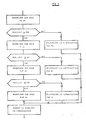
- the long delay inverse function is performed by the microprocessor program 48, illustrated in the figure. 8 and described below.
- the intensity INTPHA is the aforementioned value of the intensity of PHAse blocked at the last peak.
- the microprocessor 4 8 compares the INTPHA value with the ILR threshold displayed by the switch 80. If the INTPHA intensity is not greater than the 1LR threshold, the overload bit, which feeds the indicator 94, is set to zero, the indicator 94 thus being off It is checked whether a multiplier factor MULRR (MUltiplier Long Cooling Delay), stored in the RAM memory, is equal to zero. If not, the MULRR multiplier is decremented and the program is terminated.
- MULRR multiplier Long Cooling Delay
- this multiplier is initialized to a number determined by the position of the long delay timer switch 78 and a TETALR value (TETA temperature of a bimetal signaled for the Long Delay function) stored in the memory.
- RAM is multiplied by a reduction factor representative of the cooling of the equivalent bimetallic strip, the new value TETALR being substituted for the old one in the memory. This sequence corresponds to a cooling of the bimetallic strip.
- a warm-up phase starts when the INTPHA intensity becomes greater than the ILR threshold.
- MULRE multiplier factor
- the MULRE multiplier is decremented and the program is terminated. If the MULRE multiplier is equal to zero the overload bit goes to the value 1 to light the indicator 9 4 and the MULRE multiplier is initialized to a number determined by the switch 78.
- An arithmetic and logic unit of the microprocessor 48 executes a setting operation squared the current and calculating a DTETAE (Delta TETA E heating) value representative of heating, which is added to the previous TETALR value stored to determine the new image temperature. If the latter is greater than a maximum TETAMAX value, the trip bit goes to 1 and causes the circuit breaker to trip. Otherwise we end the program.
- DTETAE Delta TETA E heating
- the role of the multiplying factors MULRR and MULRE is the adjustment of the rate of incrementation or decrementation of the digitized thermal image. It can be seen that adjusting the multipliers to the number three causes an operation, once out of three, which results in a time delay three times longer. These multipliers allow a choice of the long delay trigger curve.
- the short delay inverse time function is performed in an analogous manner by the flowchart according to FIG. 9. If the intensity INTPHA is less than the ICR threshold, the temperature of a simulated bimetallic strip for the short delay function TETACR is multiplied by a reduction factor representative of the cooling and the new value is entered into the RAM memory. If the intensity INTPHA exceeds the ICR threshold, it is checked whether the square of the sampled current blocked at the last peak DTETACR, which corresponds to the heating, is greater than a given maximum value, of stop BUTCR, corresponding to the passage of the trigger in time inverse to the triggering of the short delay function at constant time.
- the TETACR value is replaced in the memory by the incremented value TETACR + DTETACR and it is checked whether this new TETACR value exceeds the TETACRMAX trigger threshold. In the event of an overshoot, a tripping order is transmitted to relay 14 ensuring short time protection with reverse time. When the temperature rise DTETACR is greater than the stop value BUTCR this latter value is substituted for DTETACR and added to the value TETACR in the aforementioned manner to cause a trip or not depending on whether the new value TETACR representing the simulated bimetal temperature is whether or not above the TETACRMAX threshold.
- FIG. 10 represents the main program of the trigger according to the invention.
- the microprocessor 48 acquires the adjustment parameters introduced by the switches 72-86 of the block 54. Then it reads the value of the phase current and of the earth current supplied by the multiplexer 29, all of this data being recorded in the memory. RAM. The microprocessor 48 then proceeds to the blocking sampling at the last peak of the phase current and of the earth current as described above. It then processes the instantaneous function by checking whether the phase current blocked at the last peak exceeds the instantaneous trip threshold IIN or not.
- the program is then subdivided into two branches traversed alternately, the first consisting in the calculation of the square of the current necessary for the determination of the inverse time function and the second in the successive processing of the long delay, short delay and earth protection function .
- This separation of treatments allows a reduction in the duration of the program to a value of 1.84 milliseconds.
- the signaling and triggering instructions are issued and a new cycle is executed after waiting for synchronization respecting the cycle time of 1.84 milliseconds.
- the trigger according to the invention combines the advantages of analog triggers and digital triggers without significant complications.
Landscapes
- Emergency Protection Circuit Devices (AREA)
- Driving Mechanisms And Operating Circuits Of Arc-Extinguishing High-Tension Switches (AREA)
- Protection Of Generators And Motors (AREA)
- Elimination Of Static Electricity (AREA)
- Keying Circuit Devices (AREA)
Priority Applications (1)
| Application Number | Priority Date | Filing Date | Title |
|---|---|---|---|
| AT86400284T ATE52365T1 (de) | 1985-02-25 | 1986-02-10 | Statische ausloeseeinheit fuer leistungsschalter mit parallel zu einer analogen verarbeitungskette wirkender numerischer verarbeitungskette. |
Applications Claiming Priority (2)
| Application Number | Priority Date | Filing Date | Title |
|---|---|---|---|
| FR8503161 | 1985-02-25 | ||
| FR8503161A FR2578112B1 (fr) | 1985-02-25 | 1985-02-25 | Disjoncteur a declencheur statique a chaine de traitement numerique shunte par une chaine de traitement analogique |
Publications (2)
| Publication Number | Publication Date |
|---|---|
| EP0193448A1 true EP0193448A1 (de) | 1986-09-03 |
| EP0193448B1 EP0193448B1 (de) | 1990-04-25 |
Family
ID=9316839
Family Applications (1)
| Application Number | Title | Priority Date | Filing Date |
|---|---|---|---|
| EP86400284A Expired - Lifetime EP0193448B1 (de) | 1985-02-25 | 1986-02-10 | Statische Auslöseeinheit für Leistungsschalter mit parallel zu einer analogen Verarbeitungskette wirkender numerischer Verarbeitungskette |
Country Status (11)
| Country | Link |
|---|---|
| US (1) | US4689712A (de) |
| EP (1) | EP0193448B1 (de) |
| JP (1) | JP2509182B2 (de) |
| AT (1) | ATE52365T1 (de) |
| AU (1) | AU584034B2 (de) |
| CA (1) | CA1236909A (de) |
| DE (1) | DE3670731D1 (de) |
| ES (1) | ES8704678A1 (de) |
| FR (1) | FR2578112B1 (de) |
| PT (1) | PT82085B (de) |
| ZA (1) | ZA861192B (de) |
Cited By (3)
| Publication number | Priority date | Publication date | Assignee | Title |
|---|---|---|---|---|
| EP0289042A2 (de) * | 1987-04-30 | 1988-11-02 | Mitsubishi Denki Kabushiki Kaisha | Ausschalter |
| FR2649554A1 (fr) * | 1989-07-10 | 1991-01-11 | Gen Electric | Disjoncteur electronique utilisant un circuit numerique qui presente une possibilite de declenchement instantane |
| EP0300078B1 (de) * | 1987-07-23 | 1992-09-30 | Mitsubishi Denki Kabushiki Kaisha | Überstromdetektor und Leistungsschalter |
Families Citing this family (110)
| Publication number | Priority date | Publication date | Assignee | Title |
|---|---|---|---|---|
| FR2578091B1 (fr) * | 1985-02-25 | 1988-08-05 | Merlin Gerin | Disjoncteur a declencheur statique numerique dote d'un circuit de calibrage |
| US4866557A (en) * | 1987-01-28 | 1989-09-12 | James Fitts | Low level voltage programmable logic control |
| DE3784927T2 (de) * | 1987-07-23 | 1993-10-14 | Mitsubishi Electric Corp | Überstromdetektor. |
| US5448442A (en) * | 1988-06-22 | 1995-09-05 | Siemens Energy & Automation, Inc. | Motor controller with instantaneous trip protection |
| US5089928A (en) * | 1989-08-31 | 1992-02-18 | Square D Company | Processor controlled circuit breaker trip system having reliable status display |
| US5136458A (en) * | 1989-08-31 | 1992-08-04 | Square D Company | Microcomputer based electronic trip system for circuit breakers |
| US5136457A (en) * | 1989-08-31 | 1992-08-04 | Square D Company | Processor controlled circuit breaker trip system having an intelligent rating plug |
| US5038246A (en) * | 1989-08-31 | 1991-08-06 | Square D Company | Fault powered, processor controlled circuit breaker trip system having reliable tripping operation |
| GB2244183B (en) * | 1990-05-16 | 1993-12-22 | Plessey Aerospace Limited | A control circuit for a solid state switching device |
| CA2050223C (en) * | 1990-09-27 | 1995-10-10 | Richard W. Waltz | Overload current protection apparatus |
| US5335135A (en) * | 1991-08-30 | 1994-08-02 | Siemens Energy & Automation, Inc. | Fault recording system for an electric power trip unit |
| US5311392A (en) * | 1991-08-30 | 1994-05-10 | Siemens Energy & Automation, Inc. | Dual processor electric power trip unit |
| JP2857529B2 (ja) * | 1992-03-04 | 1999-02-17 | 三菱電機株式会社 | 回路遮断器 |
| US5369542A (en) * | 1992-03-06 | 1994-11-29 | Siemens Energy & Automation, Inc. | Dual trip circuit for circuit breaker |
| US5570262A (en) * | 1994-02-25 | 1996-10-29 | Siemens Energy & Automation, Inc. | Hybrid overload relay |
| US5633774A (en) * | 1994-02-25 | 1997-05-27 | Siemens Energy & Automation Inc | Electronic overload relay power source |
| US5581433A (en) * | 1994-04-22 | 1996-12-03 | Unitrode Corporation | Electronic circuit breaker |
| IT1292453B1 (it) | 1997-07-02 | 1999-02-08 | Aeg Niederspannungstech Gmbh | Gruppo rotante di contatti per interrutttori di alta portata |
| DE19819242B4 (de) * | 1998-04-29 | 2005-11-10 | Ge Power Controls Polska Sp.Z.O.O. | Thermomagnetischer Leistungsschalter |
| US6114641A (en) * | 1998-05-29 | 2000-09-05 | General Electric Company | Rotary contact assembly for high ampere-rated circuit breakers |
| US6087913A (en) * | 1998-11-20 | 2000-07-11 | General Electric Company | Circuit breaker mechanism for a rotary contact system |
| US6037555A (en) * | 1999-01-05 | 2000-03-14 | General Electric Company | Rotary contact circuit breaker venting arrangement including current transformer |
| US6166344A (en) * | 1999-03-23 | 2000-12-26 | General Electric Company | Circuit breaker handle block |
| US6262872B1 (en) | 1999-06-03 | 2001-07-17 | General Electric Company | Electronic trip unit with user-adjustable sensitivity to current spikes |
| US6268991B1 (en) | 1999-06-25 | 2001-07-31 | General Electric Company | Method and arrangement for customizing electronic circuit interrupters |
| US6218917B1 (en) | 1999-07-02 | 2001-04-17 | General Electric Company | Method and arrangement for calibration of circuit breaker thermal trip unit |
| US6188036B1 (en) | 1999-08-03 | 2001-02-13 | General Electric Company | Bottom vented circuit breaker capable of top down assembly onto equipment |
| US6710988B1 (en) | 1999-08-17 | 2004-03-23 | General Electric Company | Small-sized industrial rated electric motor starter switch unit |
| US6252365B1 (en) | 1999-08-17 | 2001-06-26 | General Electric Company | Breaker/starter with auto-configurable trip unit |
| US6396369B1 (en) | 1999-08-27 | 2002-05-28 | General Electric Company | Rotary contact assembly for high ampere-rated circuit breakers |
| US6175288B1 (en) | 1999-08-27 | 2001-01-16 | General Electric Company | Supplemental trip unit for rotary circuit interrupters |
| US6232570B1 (en) | 1999-09-16 | 2001-05-15 | General Electric Company | Arcing contact arrangement |
| US6326869B1 (en) | 1999-09-23 | 2001-12-04 | General Electric Company | Clapper armature system for a circuit breaker |
| US6239395B1 (en) | 1999-10-14 | 2001-05-29 | General Electric Company | Auxiliary position switch assembly for a circuit breaker |
| US6229413B1 (en) | 1999-10-19 | 2001-05-08 | General Electric Company | Support of stationary conductors for a circuit breaker |
| US6317018B1 (en) | 1999-10-26 | 2001-11-13 | General Electric Company | Circuit breaker mechanism |
| US6232856B1 (en) | 1999-11-02 | 2001-05-15 | General Electric Company | Magnetic shunt assembly |
| ES2249875T3 (es) | 1999-11-03 | 2006-04-01 | AEG NIEDERSPANNUNGSTECHNIK GMBH & CO. KG | Disposicion de brazo de contacto rotatorio para disyuntor. |
| US6377144B1 (en) | 1999-11-03 | 2002-04-23 | General Electric Company | Molded case circuit breaker base and mid-cover assembly |
| US6300586B1 (en) | 1999-12-09 | 2001-10-09 | General Electric Company | Arc runner retaining feature |
| US6310307B1 (en) | 1999-12-17 | 2001-10-30 | General Electric Company | Circuit breaker rotary contact arm arrangement |
| US6184761B1 (en) | 1999-12-20 | 2001-02-06 | General Electric Company | Circuit breaker rotary contact arrangement |
| US6172584B1 (en) | 1999-12-20 | 2001-01-09 | General Electric Company | Circuit breaker accessory reset system |
| US6215379B1 (en) | 1999-12-23 | 2001-04-10 | General Electric Company | Shunt for indirectly heated bimetallic strip |
| US6281461B1 (en) | 1999-12-27 | 2001-08-28 | General Electric Company | Circuit breaker rotor assembly having arc prevention structure |
| US6346869B1 (en) | 1999-12-28 | 2002-02-12 | General Electric Company | Rating plug for circuit breakers |
| US6211758B1 (en) | 2000-01-11 | 2001-04-03 | General Electric Company | Circuit breaker accessory gap control mechanism |
| US6239677B1 (en) | 2000-02-10 | 2001-05-29 | General Electric Company | Circuit breaker thermal magnetic trip unit |
| US6429759B1 (en) | 2000-02-14 | 2002-08-06 | General Electric Company | Split and angled contacts |
| US6281458B1 (en) | 2000-02-24 | 2001-08-28 | General Electric Company | Circuit breaker auxiliary magnetic trip unit with pressure sensitive release |
| US6313425B1 (en) | 2000-02-24 | 2001-11-06 | General Electric Company | Cassette assembly with rejection features |
| US6204743B1 (en) | 2000-02-29 | 2001-03-20 | General Electric Company | Dual connector strap for a rotary contact circuit breaker |
| US6404314B1 (en) | 2000-02-29 | 2002-06-11 | General Electric Company | Adjustable trip solenoid |
| US6448521B1 (en) | 2000-03-01 | 2002-09-10 | General Electric Company | Blocking apparatus for circuit breaker contact structure |
| US6340925B1 (en) | 2000-03-01 | 2002-01-22 | General Electric Company | Circuit breaker mechanism tripping cam |
| US6379196B1 (en) | 2000-03-01 | 2002-04-30 | General Electric Company | Terminal connector for a circuit breaker |
| US6346868B1 (en) | 2000-03-01 | 2002-02-12 | General Electric Company | Circuit interrupter operating mechanism |
| US6366438B1 (en) | 2000-03-06 | 2002-04-02 | General Electric Company | Circuit interrupter rotary contact arm |
| US6459349B1 (en) | 2000-03-06 | 2002-10-01 | General Electric Company | Circuit breaker comprising a current transformer with a partial air gap |
| US6211757B1 (en) | 2000-03-06 | 2001-04-03 | General Electric Company | Fast acting high force trip actuator |
| US6496347B1 (en) | 2000-03-08 | 2002-12-17 | General Electric Company | System and method for optimization of a circuit breaker mechanism |
| US6429659B1 (en) | 2000-03-09 | 2002-08-06 | General Electric Company | Connection tester for an electronic trip unit |
| US6366188B1 (en) | 2000-03-15 | 2002-04-02 | General Electric Company | Accessory and recess identification system for circuit breakers |
| US6232859B1 (en) | 2000-03-15 | 2001-05-15 | General Electric Company | Auxiliary switch mounting configuration for use in a molded case circuit breaker |
| US6218919B1 (en) | 2000-03-15 | 2001-04-17 | General Electric Company | Circuit breaker latch mechanism with decreased trip time |
| US6459059B1 (en) | 2000-03-16 | 2002-10-01 | General Electric Company | Return spring for a circuit interrupter operating mechanism |
| US6421217B1 (en) | 2000-03-16 | 2002-07-16 | General Electric Company | Circuit breaker accessory reset system |
| US6586693B2 (en) | 2000-03-17 | 2003-07-01 | General Electric Company | Self compensating latch arrangement |
| US6639168B1 (en) | 2000-03-17 | 2003-10-28 | General Electric Company | Energy absorbing contact arm stop |
| US6479774B1 (en) | 2000-03-17 | 2002-11-12 | General Electric Company | High energy closing mechanism for circuit breakers |
| US6472620B2 (en) | 2000-03-17 | 2002-10-29 | Ge Power Controls France Sas | Locking arrangement for circuit breaker draw-out mechanism |
| US6388213B1 (en) | 2000-03-17 | 2002-05-14 | General Electric Company | Locking device for molded case circuit breakers |
| US6476698B1 (en) | 2000-03-17 | 2002-11-05 | General Electric Company | Convertible locking arrangement on breakers |
| FR2806548B1 (fr) | 2000-03-17 | 2002-08-23 | Ge Power Controls France | Mecanisme extractible pour disjoncteurs |
| US6559743B2 (en) | 2000-03-17 | 2003-05-06 | General Electric Company | Stored energy system for breaker operating mechanism |
| US6373010B1 (en) | 2000-03-17 | 2002-04-16 | General Electric Company | Adjustable energy storage mechanism for a circuit breaker motor operator |
| US6747535B2 (en) | 2000-03-27 | 2004-06-08 | General Electric Company | Precision location system between actuator accessory and mechanism |
| US6995640B2 (en) * | 2000-05-16 | 2006-02-07 | General Electric Company | Pressure sensitive trip mechanism for circuit breakers |
| US6373357B1 (en) | 2000-05-16 | 2002-04-16 | General Electric Company | Pressure sensitive trip mechanism for a rotary breaker |
| US6400245B1 (en) | 2000-10-13 | 2002-06-04 | General Electric Company | Draw out interlock for circuit breakers |
| US6531941B1 (en) | 2000-10-19 | 2003-03-11 | General Electric Company | Clip for a conductor in a rotary breaker |
| US6806800B1 (en) | 2000-10-19 | 2004-10-19 | General Electric Company | Assembly for mounting a motor operator on a circuit breaker |
| US6429760B1 (en) | 2000-10-19 | 2002-08-06 | General Electric Company | Cross bar for a conductor in a rotary breaker |
| US6362711B1 (en) | 2000-11-10 | 2002-03-26 | General Electric Company | Circuit breaker cover with screw locating feature |
| US6380829B1 (en) | 2000-11-21 | 2002-04-30 | General Electric Company | Motor operator interlock and method for circuit breakers |
| WO2002049178A2 (en) | 2000-12-12 | 2002-06-20 | Tecumseh Products Company | Compressor terminal fault interruption |
| US6448522B1 (en) | 2001-01-30 | 2002-09-10 | General Electric Company | Compact high speed motor operator for a circuit breaker |
| US6476337B2 (en) | 2001-02-26 | 2002-11-05 | General Electric Company | Auxiliary switch actuation arrangement |
| US6882258B2 (en) * | 2001-02-27 | 2005-04-19 | General Electric Company | Mechanical bell alarm assembly for a circuit breaker |
| GB0120748D0 (en) | 2001-08-25 | 2001-10-17 | Lucas Aerospace Power Equip | Generator |
| US6678135B2 (en) | 2001-09-12 | 2004-01-13 | General Electric Company | Module plug for an electronic trip unit |
| US6469882B1 (en) | 2001-10-31 | 2002-10-22 | General Electric Company | Current transformer initial condition correction |
| US6804101B2 (en) | 2001-11-06 | 2004-10-12 | General Electric Company | Digital rating plug for electronic trip unit in circuit breakers |
| US7532955B2 (en) | 2002-02-25 | 2009-05-12 | General Electric Company | Distributed protection system for power distribution systems |
| US7058482B2 (en) * | 2002-02-25 | 2006-06-06 | General Electric Company | Data sample and transmission modules for power distribution systems |
| US7111195B2 (en) | 2002-02-25 | 2006-09-19 | General Electric Company | Method and system for external clock to obtain multiple synchronized redundant computers |
| AU2003216397A1 (en) * | 2002-02-25 | 2003-09-09 | General Electric Company | Electrical protection system for reliability improvement based on sensitivity analysis |
| US7747356B2 (en) | 2002-02-25 | 2010-06-29 | General Electric Company | Integrated protection, monitoring, and control system |
| US20030212473A1 (en) * | 2002-02-25 | 2003-11-13 | General Electric Company | Processing system for a power distribution system |
| DE10214234A1 (de) * | 2002-03-26 | 2003-10-23 | Siemens Ag | Auf Kurzschluss ansprechende analogelektronische Auslöseeinrichtung für einen elektrischen Leistungsschalter |
| US6788512B2 (en) * | 2002-04-16 | 2004-09-07 | General Electric Company | Electronic trip unit capable of analog and digital setting of circuit breaker setpoints |
| US7636616B2 (en) | 2003-02-25 | 2009-12-22 | General Electric Company | Protection system for power distribution systems |
| DE10343338B4 (de) * | 2003-09-12 | 2006-02-02 | Siemens Ag | Schaltvorrichtung mit Kurzschlussstromauslösung und entsprechendes Verfahren |
| US7554796B2 (en) | 2006-01-20 | 2009-06-30 | Adc Telecommunications, Inc. | Modular power distribution system and methods |
| WO2010033123A1 (en) * | 2008-09-19 | 2010-03-25 | Hewlett-Packard Development Company, L.P. | Cpu status controlled uninterruptible power supply |
| EP2446517B1 (de) * | 2009-06-26 | 2020-01-22 | Koninklijke Philips N.V. | Leistungsverteilungsvorrichtung |
| US20120002391A1 (en) * | 2010-06-30 | 2012-01-05 | Ronald Arlin Van Weelden | Apparatus for Indicating a Status of an Apparatus That Energizes a Protective Device, and Associated Method |
| US8781764B2 (en) * | 2011-03-16 | 2014-07-15 | Deere & Company | System for detecting a short circuit associated with a direct current bus |
| CN103454462B (zh) * | 2013-09-02 | 2015-12-02 | 国家电网公司 | 多功能有源模拟断路器 |
| US20240071704A1 (en) * | 2022-08-24 | 2024-02-29 | Abb Schweiz Ag | Fault current detection for solid-state circuit breakers |
Citations (1)
| Publication number | Priority date | Publication date | Assignee | Title |
|---|---|---|---|---|
| EP0133968A1 (de) * | 1983-07-29 | 1985-03-13 | Mitsubishi Denki Kabushiki Kaisha | Festkörperüberstromdetektor |
Family Cites Families (14)
| Publication number | Priority date | Publication date | Assignee | Title |
|---|---|---|---|---|
| US4324987A (en) * | 1978-05-26 | 1982-04-13 | Cyborex Laboratories, Inc. | System and method for optimizing shed/restore operations for electrical loads |
| JPS55127821A (en) * | 1979-03-27 | 1980-10-03 | Tokyo Shibaura Electric Co | Digital protection relay unit |
| US4291355A (en) * | 1979-07-30 | 1981-09-22 | General Electric Company | Programmable overload circuit |
| JPS57500313A (de) * | 1980-02-23 | 1982-02-18 | ||
| US4351012A (en) * | 1980-04-15 | 1982-09-21 | Westinghouse Electric Corp. | Circuit interrupter with digital trip unit and means to enter trip settings |
| US4377836A (en) * | 1980-04-15 | 1983-03-22 | Westinghouse Electric Corp. | Circuit interrupter with solid state digital trip unit and positive power-up feature |
| US4331999A (en) * | 1980-04-15 | 1982-05-25 | Westinghouse Electric Corp. | Circuit interrupter with digital trip unit and power supply |
| CA1193316A (en) * | 1982-05-07 | 1985-09-10 | David R. Boothman | Motor protection apparatus |
| DE3247439A1 (de) * | 1982-12-22 | 1984-07-05 | Licentia Patent-Verwaltungs-Gmbh, 6000 Frankfurt | Digitalelektronischer ueberstromausloeser |
| JPS6032512A (ja) * | 1983-07-29 | 1985-02-19 | 三菱電機株式会社 | 静止形過電流検出装置 |
| US4589052A (en) * | 1984-07-17 | 1986-05-13 | General Electric Company | Digital I2 T pickup, time bands and timing control circuits for static trip circuit breakers |
| FR2578113B1 (fr) * | 1985-02-25 | 1988-04-15 | Merlin Gerin | Declencheur statique numerique a fonctions optionnelles pour un disjoncteur electrique |
| FR2578091B1 (fr) * | 1985-02-25 | 1988-08-05 | Merlin Gerin | Disjoncteur a declencheur statique numerique dote d'un circuit de calibrage |
| FR2578092B1 (fr) * | 1985-02-25 | 1987-03-06 | Merlin Gerin | Disjoncteur a declencheur statique a echantillonnage et blocage a la derniere crete du signal |
-
1985
- 1985-02-25 FR FR8503161A patent/FR2578112B1/fr not_active Expired
-
1986
- 1986-02-10 DE DE8686400284T patent/DE3670731D1/de not_active Expired - Fee Related
- 1986-02-10 US US06/827,436 patent/US4689712A/en not_active Expired - Lifetime
- 1986-02-10 EP EP86400284A patent/EP0193448B1/de not_active Expired - Lifetime
- 1986-02-10 AT AT86400284T patent/ATE52365T1/de not_active IP Right Cessation
- 1986-02-18 ZA ZA861192A patent/ZA861192B/xx unknown
- 1986-02-19 CA CA000502232A patent/CA1236909A/en not_active Expired
- 1986-02-24 AU AU54072/86A patent/AU584034B2/en not_active Ceased
- 1986-02-24 JP JP61038955A patent/JP2509182B2/ja not_active Expired - Lifetime
- 1986-02-24 ES ES552341A patent/ES8704678A1/es not_active Expired
- 1986-02-25 PT PT82085A patent/PT82085B/pt not_active IP Right Cessation
Patent Citations (1)
| Publication number | Priority date | Publication date | Assignee | Title |
|---|---|---|---|---|
| EP0133968A1 (de) * | 1983-07-29 | 1985-03-13 | Mitsubishi Denki Kabushiki Kaisha | Festkörperüberstromdetektor |
Cited By (4)
| Publication number | Priority date | Publication date | Assignee | Title |
|---|---|---|---|---|
| EP0289042A2 (de) * | 1987-04-30 | 1988-11-02 | Mitsubishi Denki Kabushiki Kaisha | Ausschalter |
| EP0289042A3 (en) * | 1987-04-30 | 1990-07-04 | Mitsubishi Denki Kabushiki Kaisha | Circuit breaker |
| EP0300078B1 (de) * | 1987-07-23 | 1992-09-30 | Mitsubishi Denki Kabushiki Kaisha | Überstromdetektor und Leistungsschalter |
| FR2649554A1 (fr) * | 1989-07-10 | 1991-01-11 | Gen Electric | Disjoncteur electronique utilisant un circuit numerique qui presente une possibilite de declenchement instantane |
Also Published As
| Publication number | Publication date |
|---|---|
| PT82085A (fr) | 1986-03-01 |
| AU584034B2 (en) | 1989-05-11 |
| JPS61240817A (ja) | 1986-10-27 |
| FR2578112A1 (fr) | 1986-08-29 |
| ES552341A0 (es) | 1987-04-16 |
| US4689712A (en) | 1987-08-25 |
| PT82085B (pt) | 1990-04-30 |
| DE3670731D1 (de) | 1990-05-31 |
| AU5407286A (en) | 1986-08-28 |
| JP2509182B2 (ja) | 1996-06-19 |
| CA1236909A (en) | 1988-05-17 |
| ZA861192B (en) | 1986-09-24 |
| EP0193448B1 (de) | 1990-04-25 |
| FR2578112B1 (fr) | 1988-03-18 |
| ES8704678A1 (es) | 1987-04-16 |
| ATE52365T1 (de) | 1990-05-15 |
Similar Documents
| Publication | Publication Date | Title |
|---|---|---|
| EP0193448B1 (de) | Statische Auslöseeinheit für Leistungsschalter mit parallel zu einer analogen Verarbeitungskette wirkender numerischer Verarbeitungskette | |
| EP0193449B1 (de) | Statische numerische Auslöseeinheit für Leistungsschalter mit optionellen Funktionen | |
| EP0193447B1 (de) | Statische numerische Auslöseeinheit für Leistungsschalter, ausgestattet mit einer Kalibrierungsschaltung | |
| EP0194176B1 (de) | Statische numerische Auslöseeinheit für Leistungsschalter mit inverser Auslösezeitfunktion | |
| EP0195693B1 (de) | Statische Auslöseeinheit für Leistungsschalter mit Abtastung und Blockierung des letzten Scheitelwerts des Signals | |
| EP0462023B1 (de) | Statischer Schalter | |
| EP0407310B1 (de) | Festkörperauslöser mit einer Desensibilisierungsvorrichtung für den Erdschutz | |
| FR2598266A1 (fr) | Declencheur statique instantane pour un disjoncteur limiteur | |
| EP0258091A1 (de) | Selbstüberwachte, statische, numerische Auslöseeinrichtung | |
| EP0258090A1 (de) | Statischer Auslöser für Leistungsschalter mit elektronischer Kontaktabnutzungsanzeige | |
| FR2796723A1 (fr) | Dispositif electronique intelligent et procede de prediction de pannes dans un tel dispositif | |
| EP0859443A1 (de) | Schützrelais und Verfahren | |
| FR2530089A1 (fr) | Declencheur electronique analogique pour disjoncteur de protection contre les surintensites d'un reseau a courant alternatif | |
| EP1271738B1 (de) | Elektronische Auslösevorrichtung mit einem Kondensator für die Stromversorgung einer Auslösespule | |
| WO2012146619A1 (fr) | Système de protection et de supervision d'un circuit de distribution d'énergie électrique à courant continu | |
| EP0827250B1 (de) | Elektronischer Auslöser mit einem thermischen Speicher | |
| EP0536011B1 (de) | Steuerungs und Ausgangsschutzverfahren, insbesondere für eine programmierbare Steuerung | |
| EP3650875B1 (de) | Verfahren zum testen von einer elektrischen schutzeinrichtung und elektrische schutzeinrichtung, die ein solches verfahren durchführt | |
| FR2746941A1 (fr) | Systeme de controle d'energie a prepaiement avec test automatique | |
| FR2738086A1 (fr) | Circuit electronique de protection notamment pour alimentations electriques et automates programmables | |
| EP0129454A1 (de) | Messverfahren um die Verfügbarkeit einer getakteten elektrischen Stromversorgung festzustellen und Vorrichtung zu seiner Durchführung | |
| FR2458925A1 (fr) | Declencheur electronique a commande numerique pour disjoncteur |
Legal Events
| Date | Code | Title | Description |
|---|---|---|---|
| PUAI | Public reference made under article 153(3) epc to a published international application that has entered the european phase |
Free format text: ORIGINAL CODE: 0009012 |
|
| AK | Designated contracting states |
Kind code of ref document: A1 Designated state(s): AT BE CH DE GB IT LI NL SE |
|
| 17P | Request for examination filed |
Effective date: 19870214 |
|
| 17Q | First examination report despatched |
Effective date: 19880218 |
|
| ITF | It: translation for a ep patent filed |
Owner name: INTERPATENT ST.TECN. BREV. |
|
| GRAA | (expected) grant |
Free format text: ORIGINAL CODE: 0009210 |
|
| AK | Designated contracting states |
Kind code of ref document: B1 Designated state(s): AT BE CH DE GB IT LI NL SE |
|
| PG25 | Lapsed in a contracting state [announced via postgrant information from national office to epo] |
Ref country code: SE Effective date: 19900425 Ref country code: NL Effective date: 19900425 Ref country code: AT Effective date: 19900425 |
|
| REF | Corresponds to: |
Ref document number: 52365 Country of ref document: AT Date of ref document: 19900515 Kind code of ref document: T |
|
| REF | Corresponds to: |
Ref document number: 3670731 Country of ref document: DE Date of ref document: 19900531 |
|
| GBT | Gb: translation of ep patent filed (gb section 77(6)(a)/1977) | ||
| NLV1 | Nl: lapsed or annulled due to failure to fulfill the requirements of art. 29p and 29m of the patents act | ||
| PLBE | No opposition filed within time limit |
Free format text: ORIGINAL CODE: 0009261 |
|
| STAA | Information on the status of an ep patent application or granted ep patent |
Free format text: STATUS: NO OPPOSITION FILED WITHIN TIME LIMIT |
|
| ITTA | It: last paid annual fee | ||
| PG25 | Lapsed in a contracting state [announced via postgrant information from national office to epo] |
Ref country code: LI Effective date: 19910228 Ref country code: CH Effective date: 19910228 |
|
| 26N | No opposition filed | ||
| REG | Reference to a national code |
Ref country code: CH Ref legal event code: PL |
|
| PGFP | Annual fee paid to national office [announced via postgrant information from national office to epo] |
Ref country code: BE Payment date: 19930309 Year of fee payment: 8 |
|
| PG25 | Lapsed in a contracting state [announced via postgrant information from national office to epo] |
Ref country code: BE Effective date: 19940228 |
|
| BERE | Be: lapsed |
Owner name: MERLIN GERIN Effective date: 19940228 |
|
| PGFP | Annual fee paid to national office [announced via postgrant information from national office to epo] |
Ref country code: GB Payment date: 19950131 Year of fee payment: 10 |
|
| PG25 | Lapsed in a contracting state [announced via postgrant information from national office to epo] |
Ref country code: GB Effective date: 19960210 |
|
| GBPC | Gb: european patent ceased through non-payment of renewal fee |
Effective date: 19960210 |
|
| PGFP | Annual fee paid to national office [announced via postgrant information from national office to epo] |
Ref country code: DE Payment date: 19970210 Year of fee payment: 12 |
|
| PG25 | Lapsed in a contracting state [announced via postgrant information from national office to epo] |
Ref country code: DE Free format text: LAPSE BECAUSE OF NON-PAYMENT OF DUE FEES Effective date: 19981103 |
|
| PG25 | Lapsed in a contracting state [announced via postgrant information from national office to epo] |
Ref country code: IT Free format text: LAPSE BECAUSE OF NON-PAYMENT OF DUE FEES;WARNING: LAPSES OF ITALIAN PATENTS WITH EFFECTIVE DATE BEFORE 2007 MAY HAVE OCCURRED AT ANY TIME BEFORE 2007. THE CORRECT EFFECTIVE DATE MAY BE DIFFERENT FROM THE ONE RECORDED. Effective date: 20050210 |