EP0193048B1 - Ultraschallwandler - Google Patents
Ultraschallwandler Download PDFInfo
- Publication number
- EP0193048B1 EP0193048B1 EP86101894A EP86101894A EP0193048B1 EP 0193048 B1 EP0193048 B1 EP 0193048B1 EP 86101894 A EP86101894 A EP 86101894A EP 86101894 A EP86101894 A EP 86101894A EP 0193048 B1 EP0193048 B1 EP 0193048B1
- Authority
- EP
- European Patent Office
- Prior art keywords
- reflector
- thickness
- matching layer
- ultrasonic transducer
- acoustic matching
- Prior art date
- Legal status (The legal status is an assumption and is not a legal conclusion. Google has not performed a legal analysis and makes no representation as to the accuracy of the status listed.)
- Expired
Links
- 229920000642 polymer Polymers 0.000 claims description 12
- 239000002131 composite material Substances 0.000 claims description 9
- 239000000463 material Substances 0.000 claims description 9
- 239000000919 ceramic Substances 0.000 claims description 5
- 238000004898 kneading Methods 0.000 claims description 2
- 239000000843 powder Substances 0.000 claims description 2
- 230000001747 exhibiting effect Effects 0.000 claims 2
- 238000005259 measurement Methods 0.000 claims 1
- 239000010410 layer Substances 0.000 description 37
- 230000035945 sensitivity Effects 0.000 description 17
- 239000002033 PVDF binder Substances 0.000 description 3
- 238000010276 construction Methods 0.000 description 3
- 238000000034 method Methods 0.000 description 3
- 229920002981 polyvinylidene fluoride Polymers 0.000 description 3
- 230000005855 radiation Effects 0.000 description 3
- 238000003745 diagnosis Methods 0.000 description 2
- NKZSPGSOXYXWQA-UHFFFAOYSA-N dioxido(oxo)titanium;lead(2+) Chemical compound [Pb+2].[O-][Ti]([O-])=O NKZSPGSOXYXWQA-UHFFFAOYSA-N 0.000 description 2
- 229910052451 lead zirconate titanate Inorganic materials 0.000 description 2
- HFGPZNIAWCZYJU-UHFFFAOYSA-N lead zirconate titanate Chemical compound [O-2].[O-2].[O-2].[O-2].[O-2].[Ti+4].[Zr+4].[Pb+2] HFGPZNIAWCZYJU-UHFFFAOYSA-N 0.000 description 2
- BQCIDUSAKPWEOX-UHFFFAOYSA-N 1,1-Difluoroethene Chemical compound FC(F)=C BQCIDUSAKPWEOX-UHFFFAOYSA-N 0.000 description 1
- 239000004677 Nylon Substances 0.000 description 1
- 229930182556 Polyacetal Natural products 0.000 description 1
- 238000004458 analytical method Methods 0.000 description 1
- 229910002113 barium titanate Inorganic materials 0.000 description 1
- JRPBQTZRNDNNOP-UHFFFAOYSA-N barium titanate Chemical compound [Ba+2].[Ba+2].[O-][Ti]([O-])([O-])[O-] JRPBQTZRNDNNOP-UHFFFAOYSA-N 0.000 description 1
- 230000007423 decrease Effects 0.000 description 1
- 229920001778 nylon Polymers 0.000 description 1
- 229920002239 polyacrylonitrile Polymers 0.000 description 1
- 229920006267 polyester film Polymers 0.000 description 1
- 229920001721 polyimide Polymers 0.000 description 1
- 239000002861 polymer material Substances 0.000 description 1
- 229920006324 polyoxymethylene Polymers 0.000 description 1
- 229920002620 polyvinyl fluoride Polymers 0.000 description 1
- 230000000644 propagated effect Effects 0.000 description 1
- 239000011241 protective layer Substances 0.000 description 1
- XLYOFNOQVPJJNP-UHFFFAOYSA-N water Substances O XLYOFNOQVPJJNP-UHFFFAOYSA-N 0.000 description 1
Images


Classifications
-
- G—PHYSICS
- G01—MEASURING; TESTING
- G01H—MEASUREMENT OF MECHANICAL VIBRATIONS OR ULTRASONIC, SONIC OR INFRASONIC WAVES
- G01H11/00—Measuring mechanical vibrations or ultrasonic, sonic or infrasonic waves by detecting changes in electric or magnetic properties
- G01H11/06—Measuring mechanical vibrations or ultrasonic, sonic or infrasonic waves by detecting changes in electric or magnetic properties by electric means
- G01H11/08—Measuring mechanical vibrations or ultrasonic, sonic or infrasonic waves by detecting changes in electric or magnetic properties by electric means using piezoelectric devices
-
- G—PHYSICS
- G10—MUSICAL INSTRUMENTS; ACOUSTICS
- G10K—SOUND-PRODUCING DEVICES; METHODS OR DEVICES FOR PROTECTING AGAINST, OR FOR DAMPING, NOISE OR OTHER ACOUSTIC WAVES IN GENERAL; ACOUSTICS NOT OTHERWISE PROVIDED FOR
- G10K11/00—Methods or devices for transmitting, conducting or directing sound in general; Methods or devices for protecting against, or for damping, noise or other acoustic waves in general
- G10K11/18—Methods or devices for transmitting, conducting or directing sound
- G10K11/20—Reflecting arrangements
-
- Y—GENERAL TAGGING OF NEW TECHNOLOGICAL DEVELOPMENTS; GENERAL TAGGING OF CROSS-SECTIONAL TECHNOLOGIES SPANNING OVER SEVERAL SECTIONS OF THE IPC; TECHNICAL SUBJECTS COVERED BY FORMER USPC CROSS-REFERENCE ART COLLECTIONS [XRACs] AND DIGESTS
- Y10—TECHNICAL SUBJECTS COVERED BY FORMER USPC
- Y10S—TECHNICAL SUBJECTS COVERED BY FORMER USPC CROSS-REFERENCE ART COLLECTIONS [XRACs] AND DIGESTS
- Y10S310/00—Electrical generator or motor structure
- Y10S310/80—Piezoelectric polymers, e.g. PVDF
Definitions
- This invention relates to an ultrasonic transducer and, more particularly, to an ultrasonic transducer well-suited for use underwater or for diagnosis of a living body.
- Ultrasonic transducers generally make use of a piezoelectric member which, as is well-known in the art, may be a ceramic piezoelectric member consisting of lead zirconate titanate, barium titanate, lead titanate or the like, a piezoelectric polymer member consisting of polyvinylidene fluoride or the like, or a composite piezoelectric member consisting of a polymer and a ceramic.
- the piezoelectric polymer member and the composite piezoelectric member have much higher workability and a lower acoustic impedence than the ceramic piezoelectric member and for this reason have come to be widely employed in ultrasonic transducers for use underwater or for diagnosis of a living body.
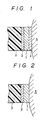
- Fig. 2 illustrates an example of the cross-sectional structure of an ultrasonic transducer using a piezoelectric polymer member.
- the transducer includes a piezoelectric body 1 obtained by providing each of the opposing main surfaces of a flat, plate- shaped piezoelectric polymer member with an electrode, not shown.
- the piezoelectric body 1 has a reflector 2 deposited on one of its surfaces and is affixed to a support member 3 via the reflector 2.
- Numeral 5 denotes a specimen undergoing examination.
- ⁇ 1 represents the sonic wavelength inside the piezoelectric body 1 at a frequency which is one half the free resonance frequency of the piezoelectric body 1.
- the thickness of the reflector 2 is set to X2/4 (where X2 is the sonic wavelength inside the reflector).
- X2 is the sonic wavelength inside the reflector.
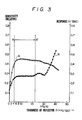
- the graph of Fig. 3 shows the results of analyzing the sensitivity and response of an ultrasonic transducer when the thickness of the reflector 2 is varied from 0 to ⁇ 2/3.
- the analytic method is in line with the principle of analyzing, by a gradualistic method (or sequence definition equation method), the amplitude of a pressure wave produced under the application of a single voltage pulse, as set forth in the specification of Japanese Patent Application Laid-Open No. 60 185 499 (published 20.9.85).
- the thickness of the reflector 2 is plotted along the horizontal axis, and both the sensitivity (relative values) and response of the ultrasonic transducer are plotted along the vertical axis.
- the characters S and R indicate the analytical data representative of sensitivity and response, respectively, and f stands for frequency (MHz).
- f stands for frequency (MHz).
- Table 1 The various materials analyzed and the corresponding acoustic impedences are shown in Table 1. It will be understood from Fig.
- the present invention is directed to an ultrasonic transducer of the type shown in Fig. 1, which is formed from a polymeric or composite piezoelectric member, the surface of the piezoelectric body 1, namely the surface that receives the ultrasonic wave, has an acoustic matching layer 4 deposited thereon to serve as a protective layer for protecting the piezoelectric member and the electrode formed on the abovementioned surface.
- This ultrasonic transducer ordinarily is used by being brought into contact with the specimen 5 through the intermediary of the acoustic matching layer 4.
- the ultrasonic transducer described in the abovementioned JP-B2-59-9000 does not possess an acoustic matching layer and the specification does not go beyond a description of the polymeric piezoelectric body.
- the thickness and acoustic impedence of the acoustic matching layer are important factors which influence various characteristics of the ultrasonic transducer.
- Common technical knowledge in the prior art is that ⁇ 3/4 is the preferred acoustic matching layer thickness (where ⁇ 3/4 is the sonic wavelength inside the acoustic matching layer).
- ⁇ 3/4 is indeed the optimum thickness of the acoustic matching layer has not been investigated, and neither has the relationship between the acoustic matching layer thickness and the reflector thickness.
- an ultrasonic transducer is known using such material as PVDF which can resonant at a frequency less than the free resonance frequency of the piezoelectric material used in the transducer. More specifically it is emphasized in this document that because it is difficult to make a polymer piezoelectrical material very thin, it is difficult to obtain a piezoelectric vibrator which exhibits low free resonant frequency. Therefore it is suggested to provide a transducer made from a material having a thickness of less than 100 ⁇ m, which transducer exhibits a resonance frequency less than 10 MHz.
- a (or two) layer(s) is (are) provided with either (both) of the acoustic radiation side or (and) the opposite side of the transducer.
- the additional layer(s) exhibit(s) an acoustic impedence Z larger than 2 x Zo, where Zo is the acoustic impedence of the transducer.
- the radiation efficiency (referred to in the following as sensitivity S) is defined as the ratio of acoustic energy radiated from the piezoelectric member to acoustic energy propagated to the object.
- Phase characteristic (referred to in the following as response R) for the transducer having a reflector is determined by the phase difference between a wave reflected at the boundary between the piezoelectric body and the reflector and a wave reflected at the boundary between the reflector and the air which is adjacent to the outer face of the reflector. The phase characteristic influences the resolution of the transducer.
- the thickness of the reflector is so large that the wave reflected at the boundary between the piezoelectric body and the reflector may not interfere with the wave reflected at the boundary between the reflector and the adjacent air, or if the attenuation coefficient of the reflector is large, it is not necessary to consider the phase characteristic in assessing the characteristic of the transducer.
- the inventors of the present application found out that, in X/4 wave mode, making the reflector thin, may result in a deteriation due to an interference of the above reflected waves because the wave reflected at the boundary between the reflector and the adjacent air is not negligible. In other words, the influence of the last mentioned reflected wave becomes significant in the same extent as the reflector becomes thinner.
- This object in accordance with the claim 1, is attained by presenting optimised ranges of thickness and acoustic impedance of the acoustic matching layer when the thickness of the reflector varies.
- An ultrasonic transducer has the cross-sectional structure illustrated in Fig. 1.
- the thicknesses of the acoustic matching layer 4 in examples giving optimum analytical results with respect to the thickness of the reflector 2 are illustrated graphically in Figs. 4 and 5.
- the materials and acoustic impedences used in each of the examples are illustrated in Table 1.
- the piezoelectric body 1 may consist of a piezoelectric polymer member or a composite obtained by kneading finely divided powder of a ferro-electric ceramic such as lead titanate or lead zirconate titanate with a polymeric material such as polyvinylidene fluoride, polyvinyl fluoride, nylon, polyacetal or polyacrylnitrile.
- the piezoelectric body 1 of the former is made of the polymer PVF 2 , while that of the latter is made of a composite material.
- the acoustic matching layer 4 consists of a well-known polymer material such as polyester or polyimide film or a polymer composite.
- the thickness of the acoustic matching layer 4 is plotted on the right side along the vertical axis and the analytic data indicative of the optimum thickness of the acoustic matching layer 4 are indicated by the curve T.
- Fig. 4 is for a case where the ultrasonic transducer shown in Fig. 3 is provided with the acoustic matching layer 4.
- the optimum acoustic impedence of the acoustic matching layer 4 is decided by the acoustic impedence of the piezoelectric body 1 and the acoustic impedence of the load, namely the specimen 5, and in this case is 2.0 x 10⁶ kg/m2 s, as shown in Table 1.
- the load 5 is water or a living body.
- the curve T in Fig. 4 indicates examples in which the thickness of the acoustic matching layer 4 is optimum.
- the thickness of the acoustic matching layer 4 that improves response R without detracting from sensitivity S differs depending upon the thickness of the reflector 2. It will also be understood from Fig. 4 that the optimum thickness of the acoustic matching layer 4 ranges from 26a,a/120 to 32a,a/120 (C-C') where the thickness of the reflector 2 ranges from 4 ⁇ 2/120 to 22 ⁇ 21120 (B-B').
- the curve T in the graph of Fig. 5 gives the optimum thickness of the acoustic matching layer 4 in an embodiment where a composite piezoelectric member constitutes the piezoelectric body 1. It will also be understood from Fig. 5 that the optimum thickness of the acoustic matching layer 4 ranges from 22 ⁇ 3 /120 to 287 ⁇ 3/120 (G-G') where the thickness of the reflector 2 ranges from 4X 2 /120 to 18 ⁇ 2 /120 (F-F').
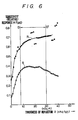
- Fig. 6 shows sensitivity and response for an ultrasonic transducer devoid of the acoustic matching layer 4
- Fig. 7 shows sensitivity and response for an ultrasonic transducer in which the acoustic matching layer 4 has a set thickness of ⁇ 3/4.
- Fig. 6 corresponds to the ultrasonic transducer having the cross-sectional structure of Fig. 2
- Fig. 7 corresponds to the ultrasonic transducer having the cross-sectional structure of Fig. 1.
- Other conditions are the same as those of Fig. 5, as shown in Table 1 (sheet 1/7).
- response R can be improved without detracting from sensitivity S if the thickness of the reflector 2 is selected- in the range 8 ⁇ 2/120 - 30X2/120 (D-D'), which is less than ⁇ 2/4.
- Fig. 7 demonstrates that by providing the acoustic matching layer 4 of thickness ⁇ 3/4, response R is markedly improved while sensitivity S is improved only marginally.
- a thickness for the acoustic matching layer 4 in the range 22 ⁇ 3/120 - 28 ⁇ 3/120 provides sensitivity and response characteristics superior to those of the conventional ultrasonic transducer having the acoustic matching layer 4 of thickness ⁇ 3/4.
- an ultrasonic transducer including an acoustic matching layer and having a reflector the thickness whereof is less than ⁇ 4/4 has the thickness of its acoustic matching layer selected in a range (15/120 - 28/120) x ⁇ s, depending upon the actual thickness of the reflector.
- An ultrasonic transducer provided with an acoustic matching layer having this optimum thickness exhibits improved response with no decline in sensitivity. This makes it possible for the ultrasonic transducer to send and receive ultrasonic signals over a wide band.
Landscapes
- Physics & Mathematics (AREA)
- Engineering & Computer Science (AREA)
- Acoustics & Sound (AREA)
- Multimedia (AREA)
- General Physics & Mathematics (AREA)
- Transducers For Ultrasonic Waves (AREA)
- Ultra Sonic Daignosis Equipment (AREA)
- Investigating Or Analyzing Materials By The Use Of Ultrasonic Waves (AREA)
- Piezo-Electric Transducers For Audible Bands (AREA)
Claims (3)
Applications Claiming Priority (2)
| Application Number | Priority Date | Filing Date | Title |
|---|---|---|---|
| JP33693/85 | 1985-02-23 | ||
| JP60033693A JPS61194999A (ja) | 1985-02-23 | 1985-02-23 | 超音波探触子 |
Publications (4)
| Publication Number | Publication Date |
|---|---|
| EP0193048A2 EP0193048A2 (de) | 1986-09-03 |
| EP0193048A3 EP0193048A3 (en) | 1987-02-04 |
| EP0193048B1 true EP0193048B1 (de) | 1990-06-06 |
| EP0193048B2 EP0193048B2 (de) | 1993-11-24 |
Family
ID=12393495
Family Applications (1)
| Application Number | Title | Priority Date | Filing Date |
|---|---|---|---|
| EP86101894A Expired - Lifetime EP0193048B2 (de) | 1985-02-23 | 1986-02-14 | Ultraschallwandler |
Country Status (4)
| Country | Link |
|---|---|
| US (1) | US4795935A (de) |
| EP (1) | EP0193048B2 (de) |
| JP (1) | JPS61194999A (de) |
| DE (1) | DE3671800D1 (de) |
Families Citing this family (25)
| Publication number | Priority date | Publication date | Assignee | Title |
|---|---|---|---|---|
| JPS62258597A (ja) * | 1986-04-25 | 1987-11-11 | Yokogawa Medical Syst Ltd | 超音波トランスデユ−サ |
| US4846001A (en) * | 1987-09-11 | 1989-07-11 | Sps Technologies, Inc. | Ultrasonic load indicating member |
| US5212671A (en) * | 1989-06-22 | 1993-05-18 | Terumo Kabushiki Kaisha | Ultrasonic probe having backing material layer of uneven thickness |
| US5608692A (en) * | 1994-02-08 | 1997-03-04 | The Whitaker Corporation | Multi-layer polymer electroacoustic transducer assembly |
| FR2720590B1 (fr) * | 1994-05-31 | 1996-06-28 | Thomson Csf | Antenne acoustique passive absorbante. |
| US5706564A (en) * | 1995-07-27 | 1998-01-13 | General Electric Company | Method for designing ultrasonic transducers using constraints on feasibility and transitional Butterworth-Thompson spectrum |
| GB9820119D0 (en) * | 1998-09-15 | 1998-11-11 | Univ Cranfield | Ultrasound couplant |
| US6371915B1 (en) * | 1999-11-02 | 2002-04-16 | Scimed Life Systems, Inc. | One-twelfth wavelength impedence matching transformer |
| US7288069B2 (en) * | 2000-02-07 | 2007-10-30 | Kabushiki Kaisha Toshiba | Ultrasonic probe and method of manufacturing the same |
| US6847153B1 (en) | 2001-06-13 | 2005-01-25 | The United States Of America As Represented By The Secretary Of The Navy | Polyurethane electrostriction |
| CN101140354B (zh) * | 2006-09-04 | 2012-01-25 | 重庆融海超声医学工程研究中心有限公司 | 谐振式超声换能器 |
| JP2009061112A (ja) * | 2007-09-06 | 2009-03-26 | Ge Medical Systems Global Technology Co Llc | 超音波探触子および超音波撮像装置 |
| JP4673930B1 (ja) * | 2010-07-08 | 2011-04-20 | 日本蚕毛染色株式会社 | 放電用シートおよびその製造方法 |
| JP5954773B2 (ja) * | 2012-03-13 | 2016-07-20 | 東芝メディカルシステムズ株式会社 | 超音波プローブおよび超音波プローブの製造方法 |
| CN105683033B (zh) | 2013-10-30 | 2018-03-09 | 丰田自动车株式会社 | 车辆及其制造方法 |
| JP6124020B2 (ja) | 2014-08-29 | 2017-05-10 | トヨタ自動車株式会社 | 車両用帯電電荷低減装置 |
| JP6128093B2 (ja) | 2014-10-16 | 2017-05-17 | トヨタ自動車株式会社 | 車両の吸気装置 |
| JP6160603B2 (ja) | 2014-12-19 | 2017-07-12 | トヨタ自動車株式会社 | 車両の冷却装置 |
| JP6201980B2 (ja) | 2014-12-25 | 2017-09-27 | トヨタ自動車株式会社 | 車両の吸気装置 |
| JP6115559B2 (ja) | 2014-12-26 | 2017-04-19 | トヨタ自動車株式会社 | 車両の排気装置 |
| JP6183383B2 (ja) | 2015-01-13 | 2017-08-23 | トヨタ自動車株式会社 | 車両 |
| JP6365316B2 (ja) | 2015-01-19 | 2018-08-01 | トヨタ自動車株式会社 | 車両の潤滑油又は燃料の供給装置 |
| EP3048017B1 (de) | 2015-01-23 | 2017-11-08 | Toyota Jidosha Kabushiki Kaisha | Dämpfungskrafterzeugungsvorrichtung für ein fahrzeug |
| JP6281501B2 (ja) | 2015-01-29 | 2018-02-21 | トヨタ自動車株式会社 | 車両の車輪支持装置 |
| JP6248962B2 (ja) | 2015-02-10 | 2017-12-20 | トヨタ自動車株式会社 | 車両の制動力発生装置 |
Family Cites Families (6)
| Publication number | Priority date | Publication date | Assignee | Title |
|---|---|---|---|---|
| JPS599000B2 (ja) * | 1979-02-13 | 1984-02-28 | 東レ株式会社 | 超音波トランスデユ−サ |
| US4383194A (en) * | 1979-05-01 | 1983-05-10 | Toray Industries, Inc. | Electro-acoustic transducer element |
| JPS586461A (ja) * | 1981-07-04 | 1983-01-14 | Nippon Dempa Kogyo Co Ltd | 超音波探触子 |
| JPS599000A (ja) * | 1982-07-09 | 1984-01-18 | 松下電器産業株式会社 | アイロンの温度調節装置 |
| US4523122A (en) * | 1983-03-17 | 1985-06-11 | Matsushita Electric Industrial Co., Ltd. | Piezoelectric ultrasonic transducers having acoustic impedance-matching layers |
| JPS60185499A (ja) * | 1984-03-05 | 1985-09-20 | Terumo Corp | 超音波探触子 |
-
1985
- 1985-02-23 JP JP60033693A patent/JPS61194999A/ja active Granted
-
1986
- 1986-02-14 DE DE8686101894T patent/DE3671800D1/de not_active Expired - Lifetime
- 1986-02-14 EP EP86101894A patent/EP0193048B2/de not_active Expired - Lifetime
-
1988
- 1988-06-02 US US07/203,591 patent/US4795935A/en not_active Expired - Lifetime
Also Published As
| Publication number | Publication date |
|---|---|
| JPH0335878B2 (de) | 1991-05-29 |
| DE3671800D1 (de) | 1990-07-12 |
| JPS61194999A (ja) | 1986-08-29 |
| US4795935A (en) | 1989-01-03 |
| EP0193048B2 (de) | 1993-11-24 |
| EP0193048A2 (de) | 1986-09-03 |
| EP0193048A3 (en) | 1987-02-04 |
Similar Documents
| Publication | Publication Date | Title |
|---|---|---|
| EP0193048B1 (de) | Ultraschallwandler | |
| US5291090A (en) | Curvilinear interleaved longitudinal-mode ultrasound transducers | |
| CA1151285A (en) | Acoustic transducer with a quarter wavelength adaptation layer as a receiver | |
| US4672591A (en) | Ultrasonic transducer | |
| Manthey et al. | Ultrasonic transducers and transducer arrays for applications in air | |
| US6225728B1 (en) | Composite piezoelectric transducer arrays with improved acoustical and electrical impedance | |
| EP0404154B1 (de) | Ultraschallprobe mit einer bedeckenden Schicht von Stoff mit unregelmässiger Dichte | |
| US4628223A (en) | Composite ceramic/polymer piezoelectric material | |
| US4523471A (en) | Composite transducer structure | |
| Saitoh et al. | A dual frequency ultrasonic probe for medical applications | |
| US4635484A (en) | Ultrasonic transducer system | |
| US8564177B2 (en) | Piezopolymer transducer with matching layer | |
| CA1252558A (en) | Ultrasonic transducer | |
| US4412147A (en) | Ultrasonic holography imaging device having a macromolecular piezoelectric element transducer | |
| US5608692A (en) | Multi-layer polymer electroacoustic transducer assembly | |
| Gururaja | Piezoelectric transducers for medical ultrasonic imaging | |
| JPH03274899A (ja) | 超音波変換器 | |
| JP2682342B2 (ja) | 複合圧電体 | |
| JP2554477B2 (ja) | 超音波探触子 | |
| JP2720731B2 (ja) | 複合圧電体 | |
| Feuillard et al. | Symmetric reflector ultrasonic transducer modeling and characterization: role of the matching layer on electroacoustic performance | |
| JPH03151948A (ja) | 超音波探触子 | |
| JPH0448039B2 (de) | ||
| JPS60138457A (ja) | 送受分離形超音波探触子 | |
| JPH0117320B2 (de) |
Legal Events
| Date | Code | Title | Description |
|---|---|---|---|
| PUAI | Public reference made under article 153(3) epc to a published international application that has entered the european phase |
Free format text: ORIGINAL CODE: 0009012 |
|
| 17P | Request for examination filed |
Effective date: 19860311 |
|
| AK | Designated contracting states |
Kind code of ref document: A2 Designated state(s): BE DE FR GB NL |
|
| PUAL | Search report despatched |
Free format text: ORIGINAL CODE: 0009013 |
|
| AK | Designated contracting states |
Kind code of ref document: A3 Designated state(s): BE DE FR GB NL |
|
| 17Q | First examination report despatched |
Effective date: 19880803 |
|
| GRAA | (expected) grant |
Free format text: ORIGINAL CODE: 0009210 |
|
| AK | Designated contracting states |
Kind code of ref document: B1 Designated state(s): BE DE FR GB NL |
|
| ET | Fr: translation filed | ||
| REF | Corresponds to: |
Ref document number: 3671800 Country of ref document: DE Date of ref document: 19900712 |
|
| PLBI | Opposition filed |
Free format text: ORIGINAL CODE: 0009260 |
|
| 26 | Opposition filed |
Opponent name: FLOWTEC AG Effective date: 19910304 |
|
| NLR1 | Nl: opposition has been filed with the epo |
Opponent name: FLOWTEC AG |
|
| PLAB | Opposition data, opponent's data or that of the opponent's representative modified |
Free format text: ORIGINAL CODE: 0009299OPPO |
|
| R26 | Opposition filed (corrected) |
Opponent name: ENDRESS + HAUSER FLOWTEC AG Effective date: 19910304 |
|
| NLXE | Nl: other communications concerning ep-patents (part 3 heading xe) |
Free format text: IN PAT.BUL.13/91,CORR.:ENDRESS + HAUSER FLOWTEC AG |
|
| PUAH | Patent maintained in amended form |
Free format text: ORIGINAL CODE: 0009272 |
|
| STAA | Information on the status of an ep patent application or granted ep patent |
Free format text: STATUS: PATENT MAINTAINED AS AMENDED |
|
| 27A | Patent maintained in amended form |
Effective date: 19931124 |
|
| AK | Designated contracting states |
Kind code of ref document: B2 Designated state(s): BE DE FR GB NL |
|
| ET3 | Fr: translation filed ** decision concerning opposition | ||
| NLR2 | Nl: decision of opposition | ||
| NLR3 | Nl: receipt of modified translations in the netherlands language after an opposition procedure | ||
| REG | Reference to a national code |
Ref country code: GB Ref legal event code: IF02 |
|
| PGFP | Annual fee paid to national office [announced via postgrant information from national office to epo] |
Ref country code: NL Payment date: 20050203 Year of fee payment: 20 |
|
| PGFP | Annual fee paid to national office [announced via postgrant information from national office to epo] |
Ref country code: FR Payment date: 20050208 Year of fee payment: 20 |
|
| PGFP | Annual fee paid to national office [announced via postgrant information from national office to epo] |
Ref country code: GB Payment date: 20050209 Year of fee payment: 20 |
|
| PGFP | Annual fee paid to national office [announced via postgrant information from national office to epo] |
Ref country code: DE Payment date: 20050210 Year of fee payment: 20 |
|
| PGFP | Annual fee paid to national office [announced via postgrant information from national office to epo] |
Ref country code: BE Payment date: 20050420 Year of fee payment: 20 |
|
| PG25 | Lapsed in a contracting state [announced via postgrant information from national office to epo] |
Ref country code: GB Free format text: LAPSE BECAUSE OF EXPIRATION OF PROTECTION Effective date: 20060213 |
|
| PG25 | Lapsed in a contracting state [announced via postgrant information from national office to epo] |
Ref country code: NL Free format text: LAPSE BECAUSE OF EXPIRATION OF PROTECTION Effective date: 20060214 |
|
| REG | Reference to a national code |
Ref country code: GB Ref legal event code: PE20 |
|
| NLV7 | Nl: ceased due to reaching the maximum lifetime of a patent |
Effective date: 20060214 |
|
| BE20 | Be: patent expired |
Owner name: *TERUMO K.K. TRADING AS TERUMO CORP. Effective date: 20060214 |