EP0193033A2 - Grinding and milling device for brittle material to be ground, such as cement clinker, ore, coal or the like - Google Patents
Grinding and milling device for brittle material to be ground, such as cement clinker, ore, coal or the like Download PDFInfo
- Publication number
- EP0193033A2 EP0193033A2 EP86101819A EP86101819A EP0193033A2 EP 0193033 A2 EP0193033 A2 EP 0193033A2 EP 86101819 A EP86101819 A EP 86101819A EP 86101819 A EP86101819 A EP 86101819A EP 0193033 A2 EP0193033 A2 EP 0193033A2
- Authority
- EP
- European Patent Office
- Prior art keywords
- tube mill
- classifier
- tube
- drum
- grinding
- Prior art date
- Legal status (The legal status is an assumption and is not a legal conclusion. Google has not performed a legal analysis and makes no representation as to the accuracy of the status listed.)
- Granted
Links
Images
Classifications
-
- B—PERFORMING OPERATIONS; TRANSPORTING
- B02—CRUSHING, PULVERISING, OR DISINTEGRATING; PREPARATORY TREATMENT OF GRAIN FOR MILLING
- B02C—CRUSHING, PULVERISING, OR DISINTEGRATING IN GENERAL; MILLING GRAIN
- B02C23/00—Auxiliary methods or auxiliary devices or accessories specially adapted for crushing or disintegrating not provided for in preceding groups or not specially adapted to apparatus covered by a single preceding group
- B02C23/18—Adding fluid, other than for crushing or disintegrating by fluid energy
- B02C23/24—Passing gas through crushing or disintegrating zone
- B02C23/32—Passing gas through crushing or disintegrating zone with return of oversize material to crushing or disintegrating zone
-
- B—PERFORMING OPERATIONS; TRANSPORTING
- B02—CRUSHING, PULVERISING, OR DISINTEGRATING; PREPARATORY TREATMENT OF GRAIN FOR MILLING
- B02C—CRUSHING, PULVERISING, OR DISINTEGRATING IN GENERAL; MILLING GRAIN
- B02C21/00—Disintegrating plant with or without drying of the material
- B02C21/002—Disintegrating plant with or without drying of the material using a combination of a roller mill and a drum mill
- B02C21/005—Disintegrating plant with or without drying of the material using a combination of a roller mill and a drum mill the roller mill having cooperating rollers
-
- Y—GENERAL TAGGING OF NEW TECHNOLOGICAL DEVELOPMENTS; GENERAL TAGGING OF CROSS-SECTIONAL TECHNOLOGIES SPANNING OVER SEVERAL SECTIONS OF THE IPC; TECHNICAL SUBJECTS COVERED BY FORMER USPC CROSS-REFERENCE ART COLLECTIONS [XRACs] AND DIGESTS
- Y02—TECHNOLOGIES OR APPLICATIONS FOR MITIGATION OR ADAPTATION AGAINST CLIMATE CHANGE
- Y02P—CLIMATE CHANGE MITIGATION TECHNOLOGIES IN THE PRODUCTION OR PROCESSING OF GOODS
- Y02P40/00—Technologies relating to the processing of minerals
- Y02P40/10—Production of cement, e.g. improving or optimising the production methods; Cement grinding
Definitions
- This invention relates to a device for comminuting and grinding brittle ground material such as cement clinker, ore, coal or the like, with a rotary grinding system comprising a tube mill and at least one classifier, which is preceded by a high-pressure roller press.
- a two-stage device for comminuting and grinding brittle ground material such as cement clinker that has not been pre-comminuted
- the ground material is first pressed in a first stage in the nip of a two-roll machine or roll press under relatively high pressure, which is what partly for P ismezerstBrung, partly on an article inner to the generation of cracks in the P and visibly manifested in the formation of agglomerates, can be then destroyed in a second stage in a tube mill or ball mill with a comparatively low expenditure of energy and ground to Fertiggutfö.
- the roller press operated with a high pressing force of in particular more than 2 t / cm roller length produces agglomerates (Schülpen) during material pressing, the grindability of which is considerably improved compared to unpressed material, so that the known two-stage size reduction leads overall to a significant reduction in the specific energy requirement .
- Due to the high pressing pressure of the roller press destroying the structure of, for example, pressed cement clinker granules, the agglomerates (slugs) formed have a relatively high proportion of particles already reduced to the desired cement fineness (approx. 30% less than 90 ⁇ m). This portion, which no longer has to be comminuted, can burden the tube mill in the known device during the final grinding of the agglomerates discharged from the roller press.
- the invention is based on the object, in the two-stage comminution and grinding of the type mentioned, the high-pressure roller press as the first stage and the recirculating grinding plant with tube mill and classifier as the second stage in terms of process technology and apparatus without any great structural effort with the aim of further savings the specific energy requirement by relieving the tube mill of roller press material that already has the desired finished product fineness after its deagglomeration.
- the roller press material to be discharged is not fed directly to the tube mill before or after its deagglomeration, but first to a classifier which looks out from the deagglomerated material the portion of the material which already has the desired content Finished goods have. Only the coarse material of the classifier is introduced directly or, if necessary, via a further classifier into the tube mill filled with grinding media, which relieves the tube mill of already fine material.
- a deagglomeration drum which also rotates with the outlet of the tube mill is advantageously arranged, the inlet of which is connected to the discharge of the roller press and the outlet of which is connected to the classifier.
- the two-stage comminution and grinding according to the invention has a rotary tube with two interconnected chambers, one chamber without grinding media forming the disagglomerating drum and the other chamber with grinding media forming the tube mill, with the disagglomerating Drum the material discharge line of the high-pressure roller press and the semolina return line of the classifier into the rotary tube end of the tube mill.
- the deagglomeration drum can be flanged to the discharge end of the tube mill or with the mill tube be integrated.
- the tube mill only grinds regrind whose grain size is larger than the desired fineness of the finished product.
- the product outlets from the deagglomeration drum and the tube mill converge, in that both outlets are encompassed by a common product failure housing which, in contrast to the rotary tube, is arranged in a rotationally fixed manner.
- the rotary tube jacket has openings in its area encompassed by the material failure housing for the passage of the deagglomerated material and of the ground product and, if appropriate, the conveying air flow of the tube mill.
- the sifter downstream of the deagglomerating drum immediately sifts out enough fine finished product, both from the deagglomerated roller press discharge material and from the grinding product of the tube mill. This selected fine material can no longer burden the tube mill.
- the good failure housing is connected in its upper region to the classifier, in particular air flow classifier, via a riser.
- the fine grain fraction of the deagglomeration drum and the tube mill is derived from the conveying air flow taken up to the sifter.
- a crop failure line can be connected, which leads to a conveyor, in particular bucket elevator, which transports the coarse grain fraction of the deagglomeration drum and the tube mill up to the classifier.
- the material discharged from the deagglomeration drum can thus be transported partly pneumatically and partly mechanically to a classifier. Sifting can take place in a static classifier (for example air flow classifier without rotating parts) and / or in a dynamic classifier (for example cyclone air classifier).
- the first stage of the two-stage comminution and grinding according to the invention consists of a high-pressure roller press 10 to which the feed material 11 to be comminuted, for example non-pre-comminuted cement clinker with a grain size of up to, for example, 100 mm.
- the grain size of an essential part of the feed material 11 is larger than the width of the narrowest nip of, for example, 20 mm between the two press rolls, which have a diameter of, for example, 900 mm.
- the pressing force of the rollers of the roller press 10, which presses on the material 11, is more than 2 t / cm of roller length, for example 6 to 8.6 t / cm.
- the feed material 11 is comminuted in the gap between the rollers by a combined single-grain comminution and material bed comminution.
- the feed material 11 to be shredded is fed in such a quantity to the roll gap of the press 10 via a vertical shaft arranged above the nip that the material to be shredded and drawn in between the rollers pushes the rollers apart and the particles of the feed material accumulate Crush the nip in a bed or collectively or in a material bed.
- the cement clinker emerges from the nip of the roller press 10, crushed and partially agglomerated, that is to say pressed into slugs 12, which are optionally fed via a lock 13 to the material inlet 14 of a disagglomerating drum 15, in which the slugs 12, which can be crumbled by hands, the latter
- the proportion of particles already reduced to the desired cement fineness (approx. 30% ⁇ 90 ⁇ m) is relatively high, can be resolved by circulating motion.
- a tube mill 17 filled with grinding media 16 like balls is integrated into a rotary tube.
- the outlet of the deagglomerating drum 15 and the outlet of the tube mill (17) are encompassed by a common outlet housing 24, which is arranged in a rotationally fixed manner.
- the rotary tube jacket 25 has openings 26 in its area encompassed by the material failure housing 24 for the passage of the deagglomerated material emerging from the drum 15 as well as of the grinding product coming from the tube mill 17 and of the conveying air flow.
- the crop failure housing 24 is connected to the classifier 20 via a riser 27, through which the disagglomerated material of the drum 15 and the ground product of the tube mill 17 are pneumatically transported to the classifier 20.
- a crop failure line 28 is connected, which leads to a conveyor, in particular bucket elevator 29, which mechanically transports the coarser grain fraction of the crop discharged from the crop failure housing 24 upwards to the sifter 20. If the conveying air flow 21 is not present, there would be the option of transporting all of the material emerging from the material failure housing 24 only upward to the sifter 20 via the bucket elevator 29. Conversely, the good drop line 28 shown in dashed lines and the bucket elevator 29 could be omitted if the entire good emerging from the good drop housing 24 can be pneumatically fed to the classifier 20 only via the riser 27 transport.
- the fine grain fraction is drawn off from the sifter via line 30 and dust separator 31, for example electrostatic dust separator, from which the fine finished product 32, in the exemplary embodiment the sufficiently finely ground cement, is drawn off.
- dust separator 31 for example electrostatic dust separator, from which the fine finished product 32, in the exemplary embodiment the sufficiently finely ground cement, is drawn off.
- an induced draft fan is indicated.
- the dynamic classifier 34 sifts out enough fine finished product 35 (cement) which can be combined with the finished product 32 of the dedusting system 31.
- the device according to the invention for comminuting and grinding brittle material to be ground becomes a grinding and drying installation if a hot gas flow is used as the conveying air flow 21. Overall, the invention achieves a further increase in performance and / or a reduction in the specific energy expenditure in the case of brittle material to be ground, which is energy-intensive in itself.
- the deagglomeration drum 15 can be uncoupled from the tube mill 17 and can be equipped with its own rotary drive. Drum 15 and tube mill 17 can rotate at different speeds, which can be precisely adapted to the respective needs. If the feed material 11 to be comminuted is hot, for example hot cement clinker, the deagglomeration drum 15 also acts as a cooling drum. If the conveying air flow rising in the riser is hot, it can be cooled by indirect gas cooling in order to be able to reduce the construction volume of the classifier 20 and / or the dedusting device 31 by reducing the amount of conveying air flow.
Abstract
Description
Diese Erfindung betrifft eine Einrichtung zur Zerkleinerung und Mahlung spröden Mahlgutes wie zum Beispiel Zementklinker, Erz, Kohle oder dergleichen, mit einer eine Rohrmühle und wenigstens einen Sichter umfassenden Umlaufmahlanlage, der eine Hochdruck-Walzenpresse vorgeschaltet ist.This invention relates to a device for comminuting and grinding brittle ground material such as cement clinker, ore, coal or the like, with a rotary grinding system comprising a tube mill and at least one classifier, which is preceded by a high-pressure roller press.
Man hat in letzter Zeit erhebliche Anstrengungen unternommen, die sehr geringe Energieausnutzung in den Zerkleinerungsmaschinen, insbesondere in den Rohrmühlen zu steigern. So ist eine zweistufige Einrichtung zur Zerkleinerung und Mahlung spröden Mahlgutes wie zum Beispiel nicht vorzerkleinerter Zementklinker bekannt (EP-Patentanmeldung 0 084 383), bei der das Mahlgut zunächst in einer ersten Stufe im Spalt einer Zweiwalzenmaschine beziehungsweise Walzenpresse unter relativ hohem Druck gepreßt wird, was teils zur PartikelzerstBrung, teils zur Erzeugung von Anrissen im Partikelinneren führt und sich sichtbar in der Bildung von Agglomeraten äußert, die dann in einer zweiten Stufe in einer Rohrmühle beziehungsweise Kugelmühle mit vergleichsweise geringem Energieaufwand zerstört und auf Fertiggutfeinheit gemahlen werden können. Die mit einer hohen Preßkraft von insbesondere mehr als 2 t/cm Walzenlänge betriebene Walzenpresse erzeugt bei der Materialpressung Agglomerate (Schülpen), deren Mahlbarkeit verglichen mit ungepreßtem Material erheblich verbessert ist, so daß die bekannte zweistufige Zerkleinerung insgesamt zu einer deutlichen Verminderung des spezifischen Energiebedarfs führt. Durch den hohen Preßdruck der Walzenpresse unter Zerstörung des Gefüges von zum Beispiel gepreßten Zementklinkergranalien weisen die gebildeten Agglomerate (Schülpen) einen relativ hohen Anteil bereits bis zur gewünschten Zementfeinheit reduzierter Partikel auf (ca. 30 % kleiner 90 um). Dieser Anteil, der nicht mehr weiter zerkleinert werden muß, kann bei der bekannten Einrichtung die Rohrmühle bei der Fertigmahlung der von der Walzenpresse ausgetragenen Agglomerate belasten.Recently, considerable efforts have been made to increase the very low energy utilization in the shredding machines, especially in the tube mills. A two-stage device for comminuting and grinding brittle ground material, such as cement clinker that has not been pre-comminuted, is known (EP patent application 0 084 383), in which the ground material is first pressed in a first stage in the nip of a two-roll machine or roll press under relatively high pressure, which is what partly for P artikelzerstBrung, partly on an article inner to the generation of cracks in the P and visibly manifested in the formation of agglomerates, can be then destroyed in a second stage in a tube mill or ball mill with a comparatively low expenditure of energy and ground to Fertiggutfeinheit. The roller press operated with a high pressing force of in particular more than 2 t / cm roller length produces agglomerates (Schülpen) during material pressing, the grindability of which is considerably improved compared to unpressed material, so that the known two-stage size reduction leads overall to a significant reduction in the specific energy requirement . Due to the high pressing pressure of the roller press, destroying the structure of, for example, pressed cement clinker granules, the agglomerates (slugs) formed have a relatively high proportion of particles already reduced to the desired cement fineness (approx. 30% less than 90 μm). This portion, which no longer has to be comminuted, can burden the tube mill in the known device during the final grinding of the agglomerates discharged from the roller press.
Der Erfindung liegt die Aufgabe zugrunde, bei der zweistufigen Zerkleinerung und Mahlung der eingangs genannten Art die Hochdruck-Walzenpresse als erste Stufe und die Umlaufmahlanlage mit Rohrmühle und Sichter als zweite Stufe verfahrenstechnisch optimal und apparatetechnisch ohne großen baulichen Aufwand miteinander zu koppeln mit dem Ziel weiterer Einsparung des spezifischen Energiebedarfs durch Entlastung der Rohrmühle von Walzenpressenaustragsgut, das nach seiner Desagglomerierung bereits die gewünschte Fertiggutfeinheit aufweist.The invention is based on the object, in the two-stage comminution and grinding of the type mentioned, the high-pressure roller press as the first stage and the recirculating grinding plant with tube mill and classifier as the second stage in terms of process technology and apparatus without any great structural effort with the aim of further savings the specific energy requirement by relieving the tube mill of roller press material that already has the desired finished product fineness after its deagglomeration.
Diese Aufgabe wird gemäß der Erfindung mit einer Einrichtung gelöst, die mit vorteilhaften Ausgestaltungen in den Ansprüchen 1 bis 7 gekennzeichnet ist.This object is achieved according to the invention with a device which is characterized by advantageous embodiments in claims 1 to 7.
Bei der erfindungsgemäßen zweistufigen Zerkleinerung und Mahlung mit Hochdruck-Walzenpresse und Umlaufmahlanlage wird das Walzenpressen-Austragsgut vor oder nach seiner Desagglomerierung nicht direkt der Rohrmühle zugeführt, sondern zunächst einem Sichter, der aus dem desagglomerierten Gut den vorhandenen Anteil des Gutes heraussichtet, das bereits die gewünschte Fertiggutfeinheit aufweist. Nur das Grobgut (Grieße) des Sichters wird direkt oder gegebenenfalls über einen weiteren Sichter in die mit Mahlkörpern gefüllte Rohrmühle eingeführt, wodurch die Rohrmühle von bereits ausreichend feinem Gut entlastet ist. Zur Desagglomerierung des Walzenpressen-Austragsgutes ist mit Vorteil am Gutauslauf der Rohrmühle eine mit dieser mitrotierende Desagglomeriertrommel angeordnet, deren Guteinlauf mit dem Austrag der Walzenpresse und deren Gutauslauf mit dem Sichter in Verbindung stehen.In the two-stage comminution and grinding according to the invention with a high-pressure roller press and recirculating grinding system, the roller press material to be discharged is not fed directly to the tube mill before or after its deagglomeration, but first to a classifier which looks out from the deagglomerated material the portion of the material which already has the desired content Finished goods have. Only the coarse material of the classifier is introduced directly or, if necessary, via a further classifier into the tube mill filled with grinding media, which relieves the tube mill of already fine material. In order to deagglomerate the roller press discharge material, a deagglomeration drum which also rotates with the outlet of the tube mill is advantageously arranged, the inlet of which is connected to the discharge of the roller press and the outlet of which is connected to the classifier.
Nach einem besonderen Merkmal der Erfindung weist die erfindungsgemäße zweistufige Zerkleinerung und Mahlung ein Drehrohr mit zwei miteinander in Verbindung stehenden Kammern auf, von denen die eine Kammer ohne Mahlkörper die Desagglomeriertrommel und die andere Kammer mit Mahlkörpern die Rohrmühle bilden, wobei in die Drehrohrstirnseite der Desagglomerier-Trommel die Gutaustragsleitung der Hochdruck-Walzenpresse und in die Drehrohr-Stirnseite der Rohrmühle die Grießrückführleitung des Sichters münden. Die Desagglomerier-Trommel kann am Austragsende der Rohrmühle angeflanscht oder mit dem Mühlenrohr integriert sein. Dadurch daß von den beiden Kammern des Drehrohrs nur die Rohrmühlenkammer mit Mahlkörpern, üblicherweise Metallkugeln gefüllt ist, nicht jedoch die Desagglomeriertrommel, in der die von der Hochdruck-Walzenpresse gebildeten Agglomerate autogen aufgelöst werden, verringert sich die Mahlkörpermasse und schon deswegen wird eine spürbare Reduzierung der Leistungsaufnahme des Drehrohres und damit Reduzierung des spezifischen Energiebedarfs erreicht. Hierzu kommt, daß die Rohrmühle wirklich nur Mahlgut mahlt, dessen Korngröße größer ist als die gewünschte Feinheit des Fertiggutes.According to a special feature of the invention, the two-stage comminution and grinding according to the invention has a rotary tube with two interconnected chambers, one chamber without grinding media forming the disagglomerating drum and the other chamber with grinding media forming the tube mill, with the disagglomerating Drum the material discharge line of the high-pressure roller press and the semolina return line of the classifier into the rotary tube end of the tube mill. The deagglomeration drum can be flanged to the discharge end of the tube mill or with the mill tube be integrated. The fact that of the two chambers of the rotary tube only the tube mill chamber is filled with grinding media, usually metal balls, but not the deagglomeration drum in which the agglomerates formed by the high-pressure roller press are dissolved autogenously, the grinding media mass is reduced and this is why there is a noticeable reduction in the Power consumption of the rotary tube and thus reduction of the specific energy requirement achieved. In addition, the tube mill only grinds regrind whose grain size is larger than the desired fineness of the finished product.
Bei der erfindungsgemäßen Einrichtung laufen die Gutausläufe von Desagglomeriertrommel und Rohrmühle zusammen, indem beide Ausläufe von einem gemeinsamen Gutausfallgehäuse umfaßt sind, das im Gegensatz zum Drehrohr drehfest angeordnet ist. Dazu weist der Drehrohrmantel in seinem vom Gutausfallgehäuse umfaßten Bereich Öffnungen zum Durchtritt des desagglomerierten Gutes sowie des Mahlproduktes und gegebenenfalls des Förderluftstromes der Rohrmühle auf. Der der Desagglomeriertrommel nachgeschaltete Sichter sichtet genügend feines Fertiggut also sowohl aus dem desagglomerierten Walzenpressenaustragsgut als auch aus dem Mahlprodukt der Rohrmühle sofort aus. Dieses ausgesichtete Feingut kann die Rohrmühle nicht mehr belasten.In the device according to the invention, the product outlets from the deagglomeration drum and the tube mill converge, in that both outlets are encompassed by a common product failure housing which, in contrast to the rotary tube, is arranged in a rotationally fixed manner. For this purpose, the rotary tube jacket has openings in its area encompassed by the material failure housing for the passage of the deagglomerated material and of the ground product and, if appropriate, the conveying air flow of the tube mill. The sifter downstream of the deagglomerating drum immediately sifts out enough fine finished product, both from the deagglomerated roller press discharge material and from the grinding product of the tube mill. This selected fine material can no longer burden the tube mill.
Nach einem weiteren Merkmal der Erfindung ist das Gutausfallgehäuse in seinem oberen Bereich über eine Steigleitung mit dem Sichter, insbesondere Luftstromsichter verbunden. In der Steigleitung wird die feine Kornfraktion der Desagglomeriertrommel und der Rohrmühle vom aus dieser kommenden Förderluftstrom nach oben zum Sichter mitgenommen. An den unteren Bereich des Gutausfallgehäuses kann eine Gutausfalleitung angeschlossen sein, die zu einem Förderorgan, insbesondere Becherwerk führt, welches die grobe Kornfraktion der Desagglomeriertrommel sowie der Rohrmühle nach oben zum Sichter transportiert. Das aus der Desagglomeriertrommel ausgetragene Gut kann also teilweise pneumatisch und teilweise mechanisch zu einem Sichter transportiert werden. Die Sichtung kann in einem statischen Sichter (zum Beispiel Luftstromsichter ohne rotierende Teile) und/oder in einem dynamischen Sichter (zum Beispiel Zyklon-Umluftsichter) erfolgen.According to a further feature of the invention, the good failure housing is connected in its upper region to the classifier, in particular air flow classifier, via a riser. In the riser, the fine grain fraction of the deagglomeration drum and the tube mill is derived from the conveying air flow taken up to the sifter. At the lower area of the crop failure housing, a crop failure line can be connected, which leads to a conveyor, in particular bucket elevator, which transports the coarse grain fraction of the deagglomeration drum and the tube mill up to the classifier. The material discharged from the deagglomeration drum can thus be transported partly pneumatically and partly mechanically to a classifier. Sifting can take place in a static classifier (for example air flow classifier without rotating parts) and / or in a dynamic classifier (for example cyclone air classifier).
Die Erfindung und deren weiteren Merkmale und Vorteile werden anhand der in den Figuren schematisch dargestellten Ausführungsbeispiele näher erläutert. Es zeigt:
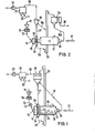
- Fig. 1 das Fließbild einer ersten Ausführungsform der erfindungsgemäßen Einrichtung zur Zerkleinerung und Mahlung spröden Mahlgutes mit vorgeschalteter Hochdruck-Walzenpresse und nachgeschalteter Umlaufmahlanlage und
- Fig. 2 das Fließbild einer anderen Ausführungsform der erfindungsgemäßen Einrichtung zur Zerkleinerung und Mahlung spröden Mahlgutes.
- Fig. 1 shows the flow diagram of a first embodiment of the device according to the invention for comminuting and grinding brittle ground material with an upstream high-pressure roller press and downstream circulation grinding plant and
- Fig. 2 shows the flow diagram of another embodiment of the device according to the invention for comminuting and grinding brittle ground material.
Bei der Ausführungsform nach Fig. 1 besteht die erste Stufe der erfindungsgemäßen zweistufigen Zerkleinerung und Mahlung aus einer Hochdruck-Walzenpresse 10, der das zu zerkleinernde Aufgabegut 11, zum Beispiel nicht vorzerkleinerter Zementklinker mit einer Korngröße bis beispielsweise 100 mm aufgegeben wird. Die Korngröße eines wesentlichen Teils des Aufgabeguts 11 ist größer als die Weite des engsten Walzenspaltes von zum Beispiel 20 mm zwischen den beiden Preßwalzen, die einen Durchmesser von beispielsweise 900 mm haben. Die auf das Gut 11 drückende Preßkraft der Walzen der Walzenpresse 10 beträgt mehr als 2 t/cm Walzenlänge, beispielsweise 6 bis 8,6 t/cm. Das Aufgabegut 11 wird im Spalt zwischen den Walzen durch eine kombinierte Einzelkornzerkleinerung und Gutbettzerkleinerung zerkleinert. Zur Durchführung des letztgenannten Zerkleinerungsprinzips wird das zu zerkleinernde Aufgabegut 11 über einen oberhalb des Walzenspaltes angeordneten vertikalen Schacht in so großer Menge dem Walzenspalt der Presse 10 zugeführt, daß das zu zerkleinernde und zwischen die Walzen eingezogene Gut die Walzen auseinanderdrückt und die Teilchen des Aufgabeguts sich im Walzenspalt in einer Schüttung beziehungsweise im Kollektiv beziehungsweise in einem Gutbett gegenseitig zerquetschen. Der Zementklinker tritt aus dem Walzenspalt der Walzenpresse 10 zerkleinert und teilweise agglomeriert, das heißt zu Schülpen 12 verpreßt aus, die gegebenenfalls über eine Schleuse 13 dem Guteinlauf 14 einer Desagglomerier-Trommel 15 zugeführt werden, in der die mit den Händen zerbröckelbaren Schülpen 12, deren Anteil an bereits bis zur gewünschten Zementfeinheit reduzierter Partikeln (ca. 30 % <90 µm) relativ hoch ist, durch Umwälzbewegung aufgelöst werden.In the embodiment according to FIG. 1, the first stage of the two-stage comminution and grinding according to the invention consists of a high-
Mit der Desagglomeriertrommel 15 ist eine mit Mahlkörpern 16 wie Kugeln gefüllte Rohrmühle 17 zu einem Drehrohr integriert. In die Drehrohrstirnseite der Rohrmühle 17 münden über eine zentrische Eingangsöffnung 18 die Grießrückführleitung 19 eines Sichters 20, im Ausführungsbeispiel eines dynamischen Sichters, zusammen mit einem Förderluftstrom 21 ein. Damit die Mahlkörper 16 der Rohrmühle 17 nicht in die Desagglomeriertrommel 15 gelangen, sind beide Kammern des Drehrohres durch eine Trennwand 22 voneinander getrennt, versehen aber mit wenigstens einer zentralen Öffnung 23, durch welche das Mahlprodukt der Rohrmühle 17 sowie der Förderluftstrom 21 in die Desagglomeriertrommel 15 gelangen.With the
Der Gutauslauf der Desagglomeriertrommel 15 und der Gutauslauf der Rohrmühle (17) sind von einem gemeinsamen Gutausfallgehäuse 24 umfaßt, das drehfest angeordnet ist. Der Drehrohrmantel 25 weist in seinem vom Gutausfallgehäuse 24 umfassten Bereich Öffnungen 26 zum Durchtritt des aus der Trommel 15 austretenden desagglomerierten Gutes sowie des von der Rohrmühle 17 kommenden Mahlproduktes sowie des Förderluftstromes auf. In seinem oberen Bereich ist das Gutausfallgehäuse 24 mit dem Sichter 20 über eine Steigleitung 27 verbunden, durch welche das desagglomerierte Gut der Trommel 15 als auch das Mahlprodukt der Rohrmühle 17 pneumatisch zum Sichter 20 transportiert werden. An den unteren Bereich des Gutausfallgehäuses 24 ist eine Gutausfalleitung 28 angeschlossen, die zu einem Förderorgan insbesondere Becherwerk 29 führt, welches die gröbere Kornfraktion des aus dem Gutausfallgehäuse 24 ausgetragenen Gutes nach oben mechanisch zum Sichter 20 transportiert. Ist der Förderluftstrom 21 nicht vorhanden, bestünde die Möglichkeit, das gesamte aus dem Gutausfallgehäuse 24 austretende Gut nur über das Becherwerk 29 nach oben zum Sichter 20 zu transportieren. Umgekehrt könnten die gestrichelt gezeichnete Gutausfalleitung 28 sowie das Becherwerk 29 weggelassen werden, wenn es gelingt, das gesamte aus dem Gutausfallgehäuse 24 austretende Gut nur über die Steigleitung 27 pneumatisch zum Sichter 20 zu transportieren. Während die Grieße den Sichter 20 über die Leitung 19 verlassen, wird aus dem Sichter die feine Kornfraktion über Leitung 30 und Staubabscheider 31, zum Beispiel elektrostatischer Staubabscheider abgezogen, aus dem das feine Fertiggut 32, im Ausführungsbeispiel der ausreichend fein gemahlene Zement abgezogen wird. Mit 33 ist ein Saugzuggebläse angezeigt.The outlet of the
Aus dem Ausführungsbeispiel wird deutlich, daß mit der erfindungsgemäßen Einrichtung zur Zerkleinerung und Mahlung spröden Mahlgutes wie zum Beispiel Zementklinker eine erhebliche Energieersparnis erreicht wird, weil die Rohrmühle 17 von dem Anteil des Walzenpressenaustragsgutes 12 entlastet wird, der nach seiner Desagglomerierung in der Trommel 15 bereits die gewünschte Feinheit des Fertiggutes 32 aufweist.From the exemplary embodiment it is clear that with the device according to the invention for comminuting and grinding brittle regrind, such as cement clinker, considerable energy savings are achieved because the
Beim Ausführungsbeispiel der Fig. 2 haben diejenigen Anlagenteile, welche mit denjenigen der Fig. 1 übereinstimmen, die gleichen Bezugsziffern. Bei Fig. 2 münden die Grießeaustragsleitung 19a des mit dem Gutausfallgehäuse 24 des Drehrohres über die Steigleitung 27 verbundenen Sichters 20, in diesem Ausführungsbeispiel ein statischer Sichter, und die untere Gutausfalleitung 28 des Gutausfallgehäuses in ein gemeinsames Förderorgan, insbesondere Becherwerk 29 ein, welches das Gut zu einem weiteren Sichter 34 transportiert, in diesem Falle ein Zyklon-Umluftsichter, dessen Grießeaustragsleitung 19b zum Guteinlauf 18 der Rohrmühle 17 des Drehrohres führt. Der dynamische Sichter 34 sichtet genügend feines Fertiggut 35 (Zement) aus, das mit dem Fertiggut 32 der Entstaubungsanlage 31 zusammengefaßt werden kann. Die erfindungsgemäße Einrichtung zur Zerkleinerung und Mahlung spröden Mahlgutes.wird zu einer Mahltrocknungsanlage, wenn als Förderluftstrom 21 ein Heißgasstrom verwendet wird. Insgesamt wird durch die Erfindung eine weitere Leistungssteigerung und/oder Verminderung des spezifischen Energieaufwandes bei der an sich energieaufwendigen Mahlung spröden Mahlgutes erreicht.In the exemplary embodiment in FIG. 2, those parts of the system which correspond to those in FIG. 1 have the same reference numbers. In Fig. 2, the
Es versteht sich, daß die Desagglomerier-Trommel 15 von der Rohrmühle 17 abgekoppelt und mit einem eigenen Drehantrieb ausgestattet sein kann. Trommel 15 und Rohrmühle 17 können mit unterschiedlichen Drehzahlen rotieren, die genau an die jeweiligen Bedürfnisse anpaßbar sind. Ist das zu zerkleinernde Aufgabegut 11 heiß, zum Beispiel heißer Zementklinker, so wirkt die Desagglomerier-Trommel 15 gleichzeitig als Kühltrommel. Ist der in der Steigleitung aufsteigende Förderluftstrom heiß, so kann dieser durch indirekte Gaskühlung abgekühlt werden, um durch Reduzierung der Förderluftstrommenge das Bauvolumen des Sichters 20 und/oder der Entstaubungseinrichtung 31 verkleinern zu können.It is understood that the
Claims (7)
Desagglomerier-Trommel (15) angeordnet ist, deren Guteinlauf (14) mit dem Austrag (12) der Walzenpresse (10) und deren Gutauslauf mit dem Sichter (20) in Verbindung stehen, dessen Austragsleitung (19, 19a) für das Grobgut (Grieße) gegebenenfalls über einen weiteren Sichter zum Guteinlauf (18) der Rohrmühle (17) führt.1. Device for comminution and grinding of brittle ground material such as cement clinker, ore, coal or the like, with a rotary grinding system comprising a tube mill and at least one classifier, which is preceded by a high-pressure roller press, characterized in that the tube mill (17) has a good outlet one co-rotating with this
Deagglomeration drum (15) is arranged, the good inlet (14) of which is connected to the discharge (12) of the roller press (10) and the good outlet of which is connected to the classifier (20), the discharge line (19, 19a) for the coarse material (semolina) ) optionally leads via a further classifier to the material inlet (18) of the tube mill (17).
Priority Applications (1)
| Application Number | Priority Date | Filing Date | Title |
|---|---|---|---|
| AT86101819T ATE63238T1 (en) | 1985-02-23 | 1986-02-13 | EQUIPMENT FOR CRUSHING AND GRINDING OF GRINDING SUCH AS CEMENT CLINKER, ORE, COAL OR THE LIKE. |
Applications Claiming Priority (2)
| Application Number | Priority Date | Filing Date | Title |
|---|---|---|---|
| DE19853506486 DE3506486A1 (en) | 1985-02-23 | 1985-02-23 | DEVICE FOR CRUSHING AND GRINDING SPROEDEN GROUND MATERIALS, FOR EXAMPLE Cement clinker, ore, coal or the like |
| DE3506486 | 1985-02-23 |
Publications (3)
| Publication Number | Publication Date |
|---|---|
| EP0193033A2 true EP0193033A2 (en) | 1986-09-03 |
| EP0193033A3 EP0193033A3 (en) | 1988-04-13 |
| EP0193033B1 EP0193033B1 (en) | 1991-05-08 |
Family
ID=6263444
Family Applications (1)
| Application Number | Title | Priority Date | Filing Date |
|---|---|---|---|
| EP86101819A Expired - Lifetime EP0193033B1 (en) | 1985-02-23 | 1986-02-13 | Grinding and milling device for brittle material to be ground, such as cement clinker, ore, coal or the like |
Country Status (8)
| Country | Link |
|---|---|
| US (1) | US4726531A (en) |
| EP (1) | EP0193033B1 (en) |
| JP (1) | JPS61227857A (en) |
| AT (1) | ATE63238T1 (en) |
| DD (1) | DD242974A5 (en) |
| DE (2) | DE3506486A1 (en) |
| DK (1) | DK81486A (en) |
| ES (1) | ES8704357A1 (en) |
Cited By (4)
| Publication number | Priority date | Publication date | Assignee | Title |
|---|---|---|---|---|
| EP0338231A2 (en) * | 1988-04-22 | 1989-10-25 | Krupp Polysius Ag | Crushing plant |
| EP0610573A2 (en) * | 1993-02-11 | 1994-08-17 | Klöckner-Humboldt-Deutz Aktiengesellschaft | Grinding method and corresponding plant |
| WO2013079416A1 (en) * | 2011-11-28 | 2013-06-06 | Maschinenfabrik Köppern Gmbh & Co. Kg | Device for sifting granular material |
| EP2604346A1 (en) * | 2011-12-16 | 2013-06-19 | Lafarge | Grinding facility |
Families Citing this family (30)
| Publication number | Priority date | Publication date | Assignee | Title |
|---|---|---|---|---|
| DE3609229A1 (en) * | 1986-03-19 | 1987-09-24 | Krupp Polysius Ag | METHOD AND SYSTEM FOR CRUSHING SPROEDEM GROUND MATERIAL |
| DE3644342A1 (en) * | 1986-12-23 | 1988-07-07 | Krupp Polysius Ag | METHOD AND SYSTEM FOR THE TWO-STAGE CRUSHING OF SPROEDEM GROUND MATERIAL |
| DE3644341A1 (en) * | 1986-12-23 | 1988-07-07 | Krupp Polysius Ag | METHOD AND SYSTEM FOR THE TWO-STAGE CRUSHING OF SPROEDEM GROUND MATERIAL |
| DE3712147A1 (en) * | 1987-04-10 | 1988-10-20 | Krupp Polysius Ag | METHOD AND SYSTEM FOR CRUSHING SPROEDEM GROUND MATERIAL |
| DE3719251A1 (en) * | 1987-06-10 | 1988-12-22 | Kloeckner Humboldt Deutz Ag | METHOD AND SYSTEM FOR CONTINUOUS PRESSURE REDUCTION OF SPROEDEN GROSSGUTES |
| CA1316890C (en) * | 1988-04-05 | 1993-04-27 | Olle Marklund | Method and apparatus for autogenous comminution primarily of overcompetent, heterogeneous mineral material |
| DE3815217A1 (en) * | 1988-05-04 | 1989-11-16 | Pfeiffer Christian Maschf | METHOD FOR CRUSHING SPROEDEM GROUND |
| DE8916267U1 (en) * | 1989-02-20 | 1996-08-08 | Kloeckner Humboldt Deutz Ag | Sifter for sifting granular material and grinding system with the activation of such a sifter |
| DD298600A5 (en) * | 1989-09-15 | 1992-03-05 | Forschungsinstitut Fuer Aufbereitung,De | TUBE BALL MILLS FOR EFFECTIVE DESAGGLOMERATION AND CRUSHING OF HIGH PRESSURE CRUSHED SPROEDEN MATERIAL |
| DE4005323A1 (en) * | 1990-02-20 | 1991-08-22 | Krupp Polysius Ag | Crushing plant for cement material - involves first stage accepting pre-crushed material, and feeding to second stage with constant output regulation |
| FR2670135B1 (en) * | 1990-12-06 | 1993-03-26 | Cle | PROCESS FOR CRUSHING BROKEN MATERIAL COMPRISING SELECTIVE DEAGGLOMERATION AND INSTALLATION FOR THE IMPLEMENTATION OF THE PROCESS. |
| US5251826A (en) * | 1992-03-13 | 1993-10-12 | Pennsylvania Crusher Corporation | Tumbling media mill and control system |
| DE4226158C2 (en) * | 1992-08-07 | 2003-04-10 | Kloeckner Humboldt Wedag | Process and plant for pressure treatment of granular goods |
| DE4228058C2 (en) * | 1992-08-24 | 1995-04-20 | Kloeckner Humboldt Deutz Ag | Plant and method for pressure treatment of granular goods |
| DE4320025A1 (en) * | 1993-06-17 | 1994-12-22 | Krupp Polysius Ag | Grinding plant and method for grinding and classifying brittle regrind |
| DE19738228A1 (en) * | 1997-09-02 | 1999-03-04 | Kloeckner Humboldt Wedag | Process for recycling grinding brittle material and grinding plant for this |
| US6149014A (en) * | 1997-12-04 | 2000-11-21 | Eriez Manufacturing Co. | Mill magnet separator and method for separating |
| US6253862B1 (en) | 1999-02-03 | 2001-07-03 | Baker Hughes Incorporated | Earth-boring bit with cutter spear point hardfacing |
| DE10056158C5 (en) * | 2000-11-13 | 2014-11-13 | Thyssenkrupp Industrial Solutions Ag | Process and plant for the production of fine material |
| BE1013926A3 (en) * | 2001-01-18 | 2002-12-03 | Magotteaux Int | TEST CRUSHER. |
| NZ590973A (en) * | 2005-04-29 | 2012-12-21 | Gtl Energy Ltd | Method to remove void spaces and vapours from carbonaceous materials, such as coal, comprising the comminution and compaction of the material |
| US20090218426A1 (en) * | 2005-06-30 | 2009-09-03 | Chang-Yu Wu | High speed orbiting ball media processors |
| WO2008112893A1 (en) * | 2007-03-13 | 2008-09-18 | Gtl Energy Ltd | Method to improve the efficiency of removal of liquid water from solid bulk fuel materials |
| AU2008255240B2 (en) * | 2007-08-01 | 2011-04-14 | Gtl Energy Ltd | Method of producing water-resistant solid fuels |
| CN101658814B (en) * | 2009-09-10 | 2011-04-20 | 倪文龙 | Enter-type closed-circuit grinding system in returning powder |
| US9333507B2 (en) | 2013-01-15 | 2016-05-10 | Knight Industrial Equipment Inc. | Automatic ball charging system for a ball mill assembly |
| DE102014006429B4 (en) * | 2014-05-02 | 2016-02-18 | Khd Humboldt Wedag Gmbh | Plant and method for grinding and sifting cement clinker with impermeability |
| CN107617501B (en) * | 2017-11-02 | 2023-10-31 | 江苏吉能达环境能源科技有限公司 | Multistage grinding superfine powder production process and system thereof |
| SE543276C2 (en) * | 2019-03-19 | 2020-11-10 | Airgrinder Ab | Method and device for grinding and drying a material or a mixture of materials |
| CN111013792A (en) * | 2019-11-29 | 2020-04-17 | 攀钢集团攀枝花钢钒有限公司 | Method for preparing powder from bituminous coal particles injected into blast furnace |
Citations (2)
| Publication number | Priority date | Publication date | Assignee | Title |
|---|---|---|---|---|
| DE1286387B (en) | 1966-01-03 | 1969-01-02 | Polysius Gmbh | Mill drying process and plant for moist material |
| EP0084383A2 (en) | 1983-01-24 | 1983-07-27 | Klöckner-Humboldt-Deutz Aktiengesellschaft | Method for the continuous breaking up by compression of friable material |
Family Cites Families (10)
| Publication number | Priority date | Publication date | Assignee | Title |
|---|---|---|---|---|
| DE378026C (en) * | 1923-07-04 | Clemens Redeligx | Milling process with step-by-step comminution of the material to be ground in the pre-grinding and fine grinding chambers arranged in a grinding housing, but separated from one another | |
| DE482630C (en) * | 1927-11-18 | 1929-09-17 | Fried Krupp Grusonwerk Akt Ges | Composite mill with intermediate sifting |
| US1902413A (en) * | 1931-04-29 | 1933-03-21 | Traylor Engineering & Mfg Comp | Method of and apparatus for multiple stage grinding |
| DE741843C (en) * | 1941-07-17 | 1943-11-18 | Polysius Ag G | Composite mill |
| DE1219779B (en) * | 1962-12-12 | 1966-06-23 | Polysius Gmbh | Mill drying process and installation for carrying out the process |
| CH469509A (en) * | 1968-03-06 | 1969-03-15 | Polysius Gmbh | Mill drying process for moist material |
| FR2061937A5 (en) * | 1969-10-03 | 1971-06-25 | Fives Lille Cail | Mineral crusher - dryer |
| GB1397377A (en) * | 1973-03-23 | 1975-06-11 | Smidth & Co As F L | Air-swept tube mills |
| FR2324367A1 (en) * | 1974-01-14 | 1977-04-15 | Fives Cail Babcock | Tubular rotary grinder - comprising a cylinder with a partition forming two grinding chambers, one of which has baffles and lifting arms |
| GB2038202B (en) * | 1978-12-29 | 1982-12-01 | Smidth & Co As F L | Dry grinding a granular material |
-
1985
- 1985-02-23 DE DE19853506486 patent/DE3506486A1/en not_active Withdrawn
-
1986
- 1986-02-13 EP EP86101819A patent/EP0193033B1/en not_active Expired - Lifetime
- 1986-02-13 AT AT86101819T patent/ATE63238T1/en not_active IP Right Cessation
- 1986-02-13 DE DE8686101819T patent/DE3679084D1/en not_active Expired - Fee Related
- 1986-02-18 ES ES552139A patent/ES8704357A1/en not_active Expired
- 1986-02-18 DD DD86287129A patent/DD242974A5/en not_active IP Right Cessation
- 1986-02-20 JP JP61034017A patent/JPS61227857A/en active Granted
- 1986-02-21 DK DK81486A patent/DK81486A/en not_active Application Discontinuation
- 1986-02-25 US US06/832,656 patent/US4726531A/en not_active Expired - Fee Related
Patent Citations (2)
| Publication number | Priority date | Publication date | Assignee | Title |
|---|---|---|---|---|
| DE1286387B (en) | 1966-01-03 | 1969-01-02 | Polysius Gmbh | Mill drying process and plant for moist material |
| EP0084383A2 (en) | 1983-01-24 | 1983-07-27 | Klöckner-Humboldt-Deutz Aktiengesellschaft | Method for the continuous breaking up by compression of friable material |
Cited By (7)
| Publication number | Priority date | Publication date | Assignee | Title |
|---|---|---|---|---|
| EP0338231A2 (en) * | 1988-04-22 | 1989-10-25 | Krupp Polysius Ag | Crushing plant |
| EP0338231A3 (en) * | 1988-04-22 | 1990-08-29 | Krupp Polysius Ag | Crushing plant |
| EP0610573A2 (en) * | 1993-02-11 | 1994-08-17 | Klöckner-Humboldt-Deutz Aktiengesellschaft | Grinding method and corresponding plant |
| EP0610573A3 (en) * | 1993-02-11 | 1995-02-01 | Kloeckner Humboldt Deutz Ag | Grinding method and corresponding plant. |
| WO2013079416A1 (en) * | 2011-11-28 | 2013-06-06 | Maschinenfabrik Köppern Gmbh & Co. Kg | Device for sifting granular material |
| EP2785472B1 (en) | 2011-11-28 | 2016-07-20 | Maschinenfabrik Köppern GmbH. & Co. KG | Device for classifying grainy products |
| EP2604346A1 (en) * | 2011-12-16 | 2013-06-19 | Lafarge | Grinding facility |
Also Published As
| Publication number | Publication date |
|---|---|
| DE3679084D1 (en) | 1991-06-13 |
| EP0193033A3 (en) | 1988-04-13 |
| JPH0117744B2 (en) | 1989-03-31 |
| DD242974A5 (en) | 1987-02-18 |
| ATE63238T1 (en) | 1991-05-15 |
| DE3506486A1 (en) | 1986-08-28 |
| ES552139A0 (en) | 1987-04-16 |
| ES8704357A1 (en) | 1987-04-16 |
| JPS61227857A (en) | 1986-10-09 |
| US4726531A (en) | 1988-02-23 |
| EP0193033B1 (en) | 1991-05-08 |
| DK81486D0 (en) | 1986-02-21 |
| DK81486A (en) | 1986-08-24 |
Similar Documents
| Publication | Publication Date | Title |
|---|---|---|
| EP0193033B1 (en) | Grinding and milling device for brittle material to be ground, such as cement clinker, ore, coal or the like | |
| EP0384101B1 (en) | Air classifier for sifting a granular material, and grinding plant employing such a classifier | |
| EP1506058B1 (en) | Circulating grinding plant comprising a mill and a sifter | |
| EP0220681B1 (en) | Device for grinding and milling damp brittle material | |
| DE19512509B4 (en) | Process for comminuting ore material | |
| EP0603481B1 (en) | Method and arrangement for milling grinding stock | |
| EP2024091B1 (en) | Roller press, in particular for interparticle crushing | |
| DE3915432C2 (en) | Process for the production of standard cement | |
| DE3719251A1 (en) | METHOD AND SYSTEM FOR CONTINUOUS PRESSURE REDUCTION OF SPROEDEN GROSSGUTES | |
| DE4337215A1 (en) | Circulating grinding plant | |
| DE3314103C2 (en) | ||
| EP0285921B1 (en) | Method and arrangement for breaking up brittle material | |
| WO2010072276A1 (en) | Method and apparatus for comminuting mineral ground product | |
| EP0413155A2 (en) | Recycling grinding arrangement for fragile material | |
| DE3518543C2 (en) | ||
| EP0610573A2 (en) | Grinding method and corresponding plant | |
| EP0399192B1 (en) | Roller mill, especially for pressure milling of granular material | |
| DE3544798C2 (en) | Device for comminution and grinding and drying (grinding drying) of moist material | |
| DE3711926A1 (en) | Device for comminuting and grinding brittle material to be ground, such as cement clinker, ore, coal or the like | |
| DE4039079A1 (en) | Limestone reduction - using hammer mill and rotary crusher before material is finely ground for cement | |
| DE4023624C2 (en) | Tube ball mills for effective deagglomeration and crushing of high-pressure crushed brittle material | |
| EP0648539B1 (en) | Closed circuit grinding plant | |
| DE4307230A1 (en) | Process and plant for comminuting the bed of brittle regrind | |
| DE3323517C2 (en) | ||
| DE3919416C2 (en) | Plant for comminuting or grinding at least two brittle good material components that can be ground differently |
Legal Events
| Date | Code | Title | Description |
|---|---|---|---|
| PUAI | Public reference made under article 153(3) epc to a published international application that has entered the european phase |
Free format text: ORIGINAL CODE: 0009012 |
|
| AK | Designated contracting states |
Kind code of ref document: A2 Designated state(s): AT DE FR GB IT |
|
| PUAL | Search report despatched |
Free format text: ORIGINAL CODE: 0009013 |
|
| AK | Designated contracting states |
Kind code of ref document: A3 Designated state(s): AT DE FR GB IT |
|
| 17P | Request for examination filed |
Effective date: 19880727 |
|
| 17Q | First examination report despatched |
Effective date: 19881024 |
|
| GRAA | (expected) grant |
Free format text: ORIGINAL CODE: 0009210 |
|
| AK | Designated contracting states |
Kind code of ref document: B1 Designated state(s): AT DE FR GB IT |
|
| REF | Corresponds to: |
Ref document number: 63238 Country of ref document: AT Date of ref document: 19910515 Kind code of ref document: T |
|
| GBT | Gb: translation of ep patent filed (gb section 77(6)(a)/1977) | ||
| REF | Corresponds to: |
Ref document number: 3679084 Country of ref document: DE Date of ref document: 19910613 |
|
| ITF | It: translation for a ep patent filed |
Owner name: SOCIETA' ITALIANA BREVETTI S.P.A. |
|
| ET | Fr: translation filed | ||
| RAP2 | Party data changed (patent owner data changed or rights of a patent transferred) |
Owner name: KLOECKNER-HUMBOLDT-DEUTZ AG |
|
| PG25 | Lapsed in a contracting state [announced via postgrant information from national office to epo] |
Ref country code: AT Free format text: LAPSE BECAUSE OF NON-PAYMENT OF DUE FEES Effective date: 19920201 |
|
| PG25 | Lapsed in a contracting state [announced via postgrant information from national office to epo] |
Ref country code: GB Effective date: 19920213 |
|
| PLBE | No opposition filed within time limit |
Free format text: ORIGINAL CODE: 0009261 |
|
| PLAA | Information modified related to event that no opposition was filed |
Free format text: ORIGINAL CODE: 0009299DELT |
|
| PLBI | Opposition filed |
Free format text: ORIGINAL CODE: 0009260 |
|
| 26N | No opposition filed | ||
| 26 | Opposition filed |
Opponent name: KRUPP POLYSIUS AG Effective date: 19920204 |
|
| GBPC | Gb: european patent ceased through non-payment of renewal fee | ||
| RDAG | Patent revoked |
Free format text: ORIGINAL CODE: 0009271 |
|
| STAA | Information on the status of an ep patent application or granted ep patent |
Free format text: STATUS: PATENT REVOKED |
|
| REG | Reference to a national code |
Ref country code: FR Ref legal event code: ST |
|
| 27W | Patent revoked |
Effective date: 19920924 |