EP0192890B2 - Matratzengestell für Sitzmöbel oder Betten - Google Patents
Matratzengestell für Sitzmöbel oder Betten Download PDFInfo
- Publication number
- EP0192890B2 EP0192890B2 EP85308819A EP85308819A EP0192890B2 EP 0192890 B2 EP0192890 B2 EP 0192890B2 EP 85308819 A EP85308819 A EP 85308819A EP 85308819 A EP85308819 A EP 85308819A EP 0192890 B2 EP0192890 B2 EP 0192890B2
- Authority
- EP
- European Patent Office
- Prior art keywords
- runs
- body support
- mattress
- springs
- support
- Prior art date
- Legal status (The legal status is an assumption and is not a legal conclusion. Google has not performed a legal analysis and makes no representation as to the accuracy of the status listed.)
- Expired - Lifetime
Links
- WYTGDNHDOZPMIW-RCBQFDQVSA-N alstonine Natural products C1=CC2=C3C=CC=CC3=NC2=C2N1C[C@H]1[C@H](C)OC=C(C(=O)OC)[C@H]1C2 WYTGDNHDOZPMIW-RCBQFDQVSA-N 0.000 claims description 2
- 230000007704 transition Effects 0.000 description 7
- 238000010276 construction Methods 0.000 description 4
- 238000004519 manufacturing process Methods 0.000 description 4
- 230000000994 depressogenic effect Effects 0.000 description 2
- OKTJSMMVPCPJKN-UHFFFAOYSA-N Carbon Chemical compound [C] OKTJSMMVPCPJKN-UHFFFAOYSA-N 0.000 description 1
- 229910052799 carbon Inorganic materials 0.000 description 1
- 238000006243 chemical reaction Methods 0.000 description 1
- 230000006835 compression Effects 0.000 description 1
- 238000007906 compression Methods 0.000 description 1
- 238000009434 installation Methods 0.000 description 1
- 230000000452 restraining effect Effects 0.000 description 1
Images
Classifications
-
- A—HUMAN NECESSITIES
- A47—FURNITURE; DOMESTIC ARTICLES OR APPLIANCES; COFFEE MILLS; SPICE MILLS; SUCTION CLEANERS IN GENERAL
- A47C—CHAIRS; SOFAS; BEDS
- A47C23/00—Spring mattresses with rigid frame or forming part of the bedstead, e.g. box springs; Divan bases; Slatted bed bases
- A47C23/005—Spring mattresses with rigid frame or forming part of the bedstead, e.g. box springs; Divan bases; Slatted bed bases foldable or dismountable
Definitions
- This invention concerns a body support, such as a mattress, or a box spring, for seats, chairs or beds.
- Conventional body supports such as box springs or mattresses, typically include an array of coil springs for supporting the body.
- the upper ends of the coil springs are attached to a wire grid made from a low carbon wire of limited resilience.
- the perimeter of the grid is attached to a border wire.
- the present invention seeks to provide a construction for a body support, such as a box spring, mattress or seat, which construction eliminates the need to rely on conventional coil springs for support.
- the present invention also seeks to provide a body support for a bed, seat or like article which will reduce the unit costs of manufacturing, handling, storage and shipment thereof. It is related to the inventions disclosed in our European Patent Application Nos. 84300783.2 (Publication No. 0151840) and 84308128.2.
- a body support that may be packaged, stored or transported prior to use in a depressed or collapsed state and later expanded or erected to a use position at the point of use.
- a body support once erected for use, display or otherwise may be subsequently collapsed or depressed into a compact state for storage, handling or shipment and then be again erected for use or otherwise, the conversion being repeatable as often as desired.
- the body support may be repeatedly adjusted between a position of use and a storage position, in which the depth and length dimensions of the body support have been substantially reduced, by folding it upon itself into two overlying sections to decrease the length thereof for storage, handling or shipment.
- a body support comprising interconnected upper and lower border frames having support means of wire-like material extending across the frames from side-to-side, and comprising a plurality of upper and lower runs, is characterised in that each run is formed from a series of spring members having a loop or coil portion on one end and a hook on the other end, the hook of one member being engaged in the loop of the adjacent member to link the members together in chain-like fashion, opposite ends of each run being connected to the side members of the frames.
- the support members may be formed by spring wire bent into non-spiral, generally two-dimensional, shapes including serpentine or sinusoidal portions extending generally in the same planes. Extending lengtwise across the top of the support members at spaced intervals a plurality of runners may be provided formed of spring wire with offset portions movably attached to the support members.
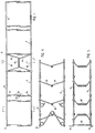
- Sections G and F each include upper and lower generally rectangular frames each of which is formed by a rectangular border wire and runner wires extending longitudinally thereof.
- the border wire of each section may be made from one piece and includes opposite side portions 70, inner end portions 72 as best shown in Fig. 5 and outer end portions 73.
- Extending between the opposite end portions of the border wire and movably attached thereto by clips are a plurality of runners 75 (see Fig. 3) having a plurality of laterally extending offset portions 76.
- the outermost positioned runners 75 are also attached to the side portion 70 of the border wires by clips 77 as best shown in Fig. 3.
- the upper and lower frames are formed by identical border wire arrangements with their inner end portions 72 serving to form pivots for folding the sections G and F relative to each other and transition section H.
- sections G and F are interconnected by the transition section H through means including straight wire connecting links 80 interconnecting the side portions 70 of the border wires of Sections G and F; and a plurality of flexible and resilient constraining means formed of spring wire and generally designated 82 in Fig. 5.
- the latter each include a lower generally inverted U-shaped part 84 having opposite legs coiled about adjacent inner border wire portions 72 of the lower frames and an upper generally U-shaped part 85 having opposite legs coiled about the adjacent inner border wire portions 72 of the upper frames.
- the lower part 84 is formed with coils at its mid-section received about the mid-section of the upper part 85 as best shown in Fig. 1. As shown in Figs.
- a plurality of the constraining means are employed throughout the transition section H across the mattress at uniformly spaced locations.
- the constraining means function to keep the pivot axes defined by the inner border wire portions 72 in the proper rectangular interrelationship with each other as shown in Fig. 1 to permit the sections F and G to be pivotable relative to the transition section H between the use and storage positions.
- the use position is shown in Fig. 1 wherein sections G, F and H extend in horizontal coplanar relationship. In the storage position, one section G or F is folded over the other section with the transition section H extending generally at right angles to the sections G and F.
- the frame members in the illustrated embodiment include a plurality of interconnected springs each of which includes an upper generally rectilinear run 90, and a lower generally rectilinear run 91 whilst a generally V-shaped intermediate run 92 forms the support members, all of the aforementioned portions lying generally in the same plane.
- the upper and lower runs 90 and 91 are united to the intermediate runs 92 through means of coil portions 93 while the intermediate runs 92 converge at a coil portion 94.
- each of the wire portions including the coils are formed integral with each other from the same piece of spring wire.
- the extremities of the upper and lower runs 90, 91 are formed with hook portions 95 through which the springs in each roware interconnected by placing the hook portions 95 in and about the coil portions 93 of the adjacent spring.
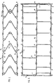
- the hook portions 95 in the illustrated embodiment are offset inwardly from the runs 90, 91 to permit their receipt in coils 93. It will thus be seen when the springs in each row are assembled, the upper rectilinear runs 90 will extend in generally a straight line across the mattress and the lower rectilinear runs 91 will extend in a generally straight line located below and in generally the same plane as the upper runs 90. Additionally, the intermediate coils 94 will be in general horizontal alignment.
- the support springs When the mattress is folded into the storage position, that is, with one section G or F located over the other section, the support springs will pivot from their erect position shown in Fig. 1 to a retracted position (not shown).
- the upperand lower runs 90, 91 of the springs are pivotally attached to the longitudinally extending runners 75 at the offset portions 76 by means of suitable clips 96 so that when pivoting between their erect and retracted positions, the springs will pivot relative to the upper and lower runners 75 and, or course, the upper and lower border wires 70, 72 which, together with the runners 75, form the upper and lower frames of the mattress.
- the springs will, of course, pivot upwardly into their erect positions shown in Fig. 1.
- the erect position of the srings is determined by the constraining means 84, 85 described above which prevents the springs from pivoting beyond their90 degree erect position when the mattress is unfolded. Additionally, once the mattress is in the use position of Fig. 1, the constraining means 84, 85 will prevent the springs from pivoting out of their erect positions as long as the mattress sections G, F and H are in the coplanar horizontal position shown in Fig. 1.
- the intermediate portions 92 of the springs Upon reflection of the springs when a load is placed on the mattress in the use position, the intermediate portions 92 of the springs will remain generally in the same plane as the upperand lower runs 90, 91 of the springs and will not deflect laterally to either side even though deflection of the springs will occur about the axes passing through coils 94 of the intermediate portions 92 of the springs. It will also be noted that due to the upper and lower rectilinear runs 90, 91 of the springs, restraining cross-wires are not required.
- a double spring arrangement may be provided along the sides of the mattress shown, for example, on the right-hand side of Fig. 2.
- a pair of springs are placed in opposed and partially overlapping relationship as best shown in Fig. 2 and with their free extremities clipped together by clips 98 which, in the illustrated embodiment, also serve to attach both springs to the runner 75 in the region of its offset portion 76.
- clips 98 which, in the illustrated embodiment, also serve to attach both springs to the runner 75 in the region of its offset portion 76.
- this arrangement can be employed throughout the mattress if it is desired to increase the support of the mattress.
- the runners 75 are made from fifteen (15) gauge spring wire while the support springs are made from thirteen (13) gauge spring wire.
- the support springs are made from thirteen (13) gauge spring wire.
- other spring configurations and gauges may be employed in keeping with the present invention.
- the use of the runners 75 and the support springs of the present invention replaces conventional grids and coil springs heretofore used in mattress construction, while providing greater resilient support at a cost believed to be significantly less than conventional spring mattress constructions.
- the sections G and F amy be placed into generally coplanar positions as best shown in Fig. 1 where the springs will provide a comfortable resilient support surface. If it is desired to fold the mattress for storage of handling one section G or F may be swung about the pivotal axes passing through the inner border wire portions 72 to place it into overlying relationship with the other section. By virtue of the fact that the support springs are constrained they will pivot relative to the upper and lower frames into the retracted position. During such pivotal movement, the constraining means will function to keep the pivot axes defined by the inner border wire portions 72 in the proper rectangularly spaced relationship relative to each other to achieve the desired movement of the sections.
Landscapes
- Mattresses And Other Support Structures For Chairs And Beds (AREA)
Claims (7)
Applications Claiming Priority (2)
| Application Number | Priority Date | Filing Date | Title |
|---|---|---|---|
| US680189 | 1984-12-10 | ||
| US06/680,189 US4654905A (en) | 1983-12-08 | 1984-12-10 | Body support for bed or seat |
Publications (4)
| Publication Number | Publication Date |
|---|---|
| EP0192890A2 EP0192890A2 (de) | 1986-09-03 |
| EP0192890A3 EP0192890A3 (en) | 1987-01-21 |
| EP0192890B1 EP0192890B1 (de) | 1990-04-04 |
| EP0192890B2 true EP0192890B2 (de) | 1993-11-03 |
Family
ID=24730088
Family Applications (1)
| Application Number | Title | Priority Date | Filing Date |
|---|---|---|---|
| EP85308819A Expired - Lifetime EP0192890B2 (de) | 1984-12-10 | 1985-12-04 | Matratzengestell für Sitzmöbel oder Betten |
Country Status (6)
| Country | Link |
|---|---|
| US (1) | US4654905A (de) |
| EP (1) | EP0192890B2 (de) |
| JP (1) | JPH0667334B2 (de) |
| AU (1) | AU579541B2 (de) |
| CA (1) | CA1246249A (de) |
| DE (1) | DE3576908D1 (de) |
Cited By (1)
| Publication number | Priority date | Publication date | Assignee | Title |
|---|---|---|---|---|
| US7469431B2 (en) | 2005-12-07 | 2008-12-30 | Stelpro Wire & Springs, Inc. | Nestable box spring foundation |
Families Citing this family (51)
| Publication number | Priority date | Publication date | Assignee | Title |
|---|---|---|---|---|
| US4770397A (en) * | 1986-10-06 | 1988-09-13 | Steadley Company | Spring wire element for foundation unit |
| US4811932A (en) * | 1987-07-06 | 1989-03-14 | Parma Corporation | Coil spring mattress core |
| US5184809A (en) * | 1991-07-15 | 1993-02-09 | Parma Corporation | Spring assembly for seating and bedding |
| US5231712A (en) * | 1992-02-04 | 1993-08-03 | Elite Support Systems, Inc. | Bedding unit and springs therefor |
| US5499414A (en) * | 1994-05-05 | 1996-03-19 | Simmons Company | Innerspring construction including improved edge characteristics |
| US5539944A (en) * | 1994-11-25 | 1996-07-30 | Parma Corporation | Foldable bed with collapsible sinuous springs |
| US5765240A (en) * | 1996-07-31 | 1998-06-16 | L&P Property Management Co. | Spring bedding product collapsible in the transverse direction, and method of making it |
| US5967499A (en) * | 1997-12-02 | 1999-10-19 | Hickory Springs Manufacturing Co. | Box spring support module |
| US6012190A (en) | 1998-07-23 | 2000-01-11 | Pharma Corporation | Foldable bed with collapsible sinuous springs |
| US7503086B2 (en) * | 2004-05-11 | 2009-03-17 | L & P Property Management Company | Foldable bedding foundation with sliders |
| US7376989B2 (en) * | 2004-05-11 | 2008-05-27 | L&P Property Management Company | Foldable bedding foundation |
| US7376988B2 (en) * | 2004-05-11 | 2008-05-27 | L&P Property Management Company | Foldable bedding foundation |
| US7406727B2 (en) * | 2004-05-11 | 2008-08-05 | L&P Property Management Company | Foldable foundation for a mattress |
| US7100989B2 (en) * | 2004-11-12 | 2006-09-05 | Lear Corporation | Collapsible seat cushion |
| US7487564B2 (en) * | 2005-01-11 | 2009-02-10 | John Miller | Articulatable spring mechanisms for items of furniture |
| USD544284S1 (en) * | 2005-10-11 | 2007-06-12 | Yi-Chen Huang | Mattress frame |
| US7270371B2 (en) * | 2005-10-27 | 2007-09-18 | Lear Corporation | Truck slouch seat |
| US7356859B2 (en) * | 2006-02-01 | 2008-04-15 | Hickory Springs Manufacturing Company | Bedding foundation support module |
| US7360263B2 (en) * | 2006-02-01 | 2008-04-22 | Hickory Springs Manufacturing Company | Bedding foundation support module |
| US20070283501A1 (en) * | 2006-06-12 | 2007-12-13 | L&P Property Management Company | Modular Bedding System and Method of Assembly |
| US20090183311A1 (en) * | 2008-01-18 | 2009-07-23 | Vy Nguyen | Bed Assemblies |
| US20090293193A1 (en) * | 2008-06-03 | 2009-12-03 | L&P Property Management Company | Collapsible bedding foundation |
| US9145073B2 (en) | 2011-03-15 | 2015-09-29 | Lear Corporation | Collapsible bolster cushion |
| US8769740B2 (en) | 2011-09-19 | 2014-07-08 | Zinus, Inc. | Collapsible, folding mattress support with adjustable elevating shoulder section |
| US8370973B1 (en) * | 2011-09-19 | 2013-02-12 | Zinus, Inc. | Collapsible, folding mattress support having the appearance of a box spring with legs |
| US8312576B1 (en) * | 2011-09-19 | 2012-11-20 | Zinus, Inc. | Sturdy, collapsible, folding mattress support having the appearance of a box spring |
| US8939510B2 (en) | 2011-10-06 | 2015-01-27 | Lear Corporation | Seat assembly having a collapsible cushion support assembly |
| US8806672B1 (en) | 2012-05-14 | 2014-08-19 | Axess Direct, Inc. | Foldable sofa mattress and method |
| US9015879B1 (en) * | 2012-05-14 | 2015-04-28 | Axess Direct, Inc. | Foldable sofa mattress and method |
| US8978176B1 (en) | 2013-05-25 | 2015-03-17 | Zinus, Inc. | Adjustable, collapsible, compact mattress support |
| US8832876B1 (en) | 2013-05-25 | 2014-09-16 | Zinus, Inc. | Collapsible, compact mattress support |
| US9185991B2 (en) | 2013-12-30 | 2015-11-17 | Axess Direct, Inc. | Uni-directional rigidifier and method |
| US10034551B2 (en) | 2014-09-22 | 2018-07-31 | L&P Property Management Company | Foldable bedding foundation having L-shaped spacers |
| US9226590B1 (en) | 2014-09-22 | 2016-01-05 | L&P Property Management Company | Foldable bedding foundation having L-shaped spacers |
| US10321767B2 (en) | 2015-02-27 | 2019-06-18 | Inno-Sports Co., Ltd. | Supports, folding mechanisms and foldable supporting frames |
| CN204670760U (zh) * | 2015-04-14 | 2015-09-30 | 格联特(厦门)休闲用品有限公司 | 一种折叠床架 |
| US10285506B2 (en) * | 2015-04-30 | 2019-05-14 | Inno-Sports Co., Ltd. | Foldable bed frame having pivotally connected frame units |
| SE539070C2 (sv) * | 2015-09-28 | 2017-04-04 | Wahlgren John | Ledad säng |
| US10813467B2 (en) | 2016-02-02 | 2020-10-27 | Xiamen Innovation Metal Products Co., Ltd. | Foldable bed frame having legs rotatable in lateral direction |
| CN206333631U (zh) | 2016-07-04 | 2017-07-18 | 路华(厦门)贸易有限公司 | 折叠床架 |
| US10188217B2 (en) | 2016-10-05 | 2019-01-29 | Jason Harrow | Collapsible bed foundation |
| US10508674B2 (en) | 2016-10-05 | 2019-12-17 | Jason Harrow | Collapsible bed foundation |
| US10595643B2 (en) | 2016-10-05 | 2020-03-24 | Jason Harrow | Mattress foundation with slidably attached components |
| CN206586700U (zh) * | 2016-10-27 | 2017-10-27 | 路华(厦门)贸易有限公司 | 一种折叠床架 |
| CN206745037U (zh) | 2016-11-10 | 2017-12-15 | 路华(厦门)贸易有限公司 | 一种折叠床框架 |
| US10610026B2 (en) * | 2017-02-15 | 2020-04-07 | John Edward Miller | Foldable, stand-alone mattress with internal spring system |
| CN208002473U (zh) | 2017-05-17 | 2018-10-26 | 革新(厦门)运动器材有限公司 | 一种铁架床靠背结构 |
| CN207626902U (zh) | 2017-05-17 | 2018-07-20 | 革新(厦门)运动器材有限公司 | 一种新型折叠床架 |
| CN210330029U (zh) | 2019-04-28 | 2020-04-17 | 革新(厦门)运动器材有限公司 | 一种折叠床支撑脚的支撑结构 |
| CN113100686B (zh) * | 2021-04-20 | 2022-08-16 | 屈宁 | 一种自动洗鞋设备 |
| US20240164534A1 (en) * | 2022-08-31 | 2024-05-23 | Abbyson Living Llc | Box spring with foldable frame |
Family Cites Families (23)
| Publication number | Priority date | Publication date | Assignee | Title |
|---|---|---|---|---|
| US149758A (en) * | 1874-04-14 | Improvement | ||
| US341246A (en) * | 1886-05-04 | Spring bed-bottom | ||
| US514898A (en) * | 1894-02-20 | Spring-bed | ||
| US516195A (en) * | 1894-03-13 | Daniel h | ||
| US399867A (en) * | 1889-03-19 | Woven-wire mattress | ||
| DE114849C (de) * | ||||
| US497156A (en) * | 1893-05-09 | Henry b | ||
| US332081A (en) * | 1885-12-08 | jeffery | ||
| US757420A (en) * | 1902-07-24 | 1904-04-12 | Watson R Smith | Wire clip for cushion-spring work. |
| US902011A (en) * | 1908-06-15 | 1908-10-27 | John A Staples | Springwork. |
| US927982A (en) * | 1908-12-26 | 1909-07-13 | Union Wire Mattress Company | Spring bed-bottom. |
| US1285721A (en) * | 1917-01-23 | 1918-11-26 | Edgar S Johnston | Bed-spring. |
| US1920176A (en) * | 1931-04-09 | 1933-08-01 | Reynolds Spring Co | Spring cushion |
| US2024307A (en) * | 1933-04-08 | 1935-12-17 | Rosenfeld Salomon | Mattressing |
| US2239877A (en) * | 1940-03-09 | 1941-04-29 | Albert James Ciullo | Bed |
| US2560842A (en) * | 1946-03-27 | 1951-07-17 | Universal Wire Spring Co | Wire spring structure for seat constructions |
| US2634427A (en) * | 1949-05-04 | 1953-04-14 | Superior Sleeprite Corp | Combination sofa and bed |
| US2773270A (en) * | 1952-09-13 | 1956-12-11 | Nachman Corp | Adjustable innerspring unit |
| US2874390A (en) * | 1956-12-03 | 1959-02-24 | Morton D Stone | Mattress and cushion construction |
| US3042395A (en) * | 1959-09-09 | 1962-07-03 | Vono Ltd | Spring assembly |
| US3085259A (en) * | 1960-05-20 | 1963-04-16 | William C Sandor | Bed spring construction |
| US4377279A (en) * | 1980-07-07 | 1983-03-22 | Steadley Company | Steel wire foundation |
| US4475724A (en) * | 1982-05-20 | 1984-10-09 | Hoover Universal, Inc. | Wire spring assembly for sofa sleeper mattresses |
-
1984
- 1984-12-10 US US06/680,189 patent/US4654905A/en not_active Expired - Lifetime
-
1985
- 1985-10-30 CA CA000494179A patent/CA1246249A/en not_active Expired
- 1985-12-03 AU AU50718/85A patent/AU579541B2/en not_active Ceased
- 1985-12-04 EP EP85308819A patent/EP0192890B2/de not_active Expired - Lifetime
- 1985-12-04 DE DE8585308819T patent/DE3576908D1/de not_active Expired - Lifetime
- 1985-12-06 JP JP60275863A patent/JPH0667334B2/ja not_active Expired - Lifetime
Cited By (1)
| Publication number | Priority date | Publication date | Assignee | Title |
|---|---|---|---|---|
| US7469431B2 (en) | 2005-12-07 | 2008-12-30 | Stelpro Wire & Springs, Inc. | Nestable box spring foundation |
Also Published As
| Publication number | Publication date |
|---|---|
| EP0192890A3 (en) | 1987-01-21 |
| JPH0667334B2 (ja) | 1994-08-31 |
| EP0192890A2 (de) | 1986-09-03 |
| AU579541B2 (en) | 1988-11-24 |
| EP0192890B1 (de) | 1990-04-04 |
| JPS61141310A (ja) | 1986-06-28 |
| CA1246249A (en) | 1988-12-06 |
| US4654905A (en) | 1987-04-07 |
| AU5071885A (en) | 1986-06-19 |
| DE3576908D1 (de) | 1990-05-10 |
Similar Documents
| Publication | Publication Date | Title |
|---|---|---|
| EP0192890B2 (de) | Matratzengestell für Sitzmöbel oder Betten | |
| EP0182944B1 (de) | Untermatratze und Verfahren zu ihrer Lagerung | |
| US7503086B2 (en) | Foldable bedding foundation with sliders | |
| US20090293193A1 (en) | Collapsible bedding foundation | |
| US20120042449A1 (en) | Collapsible Bedding Foundation | |
| US6966091B2 (en) | Coil innerspring assembly having varying degrees of firmness | |
| FI93514C (fi) | Vuoteen pohja | |
| US7406727B2 (en) | Foldable foundation for a mattress | |
| US4489450A (en) | Body support for bed or seat | |
| US7376989B2 (en) | Foldable bedding foundation | |
| US5765240A (en) | Spring bedding product collapsible in the transverse direction, and method of making it | |
| HK1000995B (en) | Stackable bedding foundation | |
| HK1000995A1 (en) | Stackable bedding foundation | |
| US7376988B2 (en) | Foldable bedding foundation | |
| US7237282B2 (en) | Stackable and stable bedding foundation | |
| US20020100118A1 (en) | Bedding or seating product with nestable stackable modules | |
| US6578213B2 (en) | Stackable bedding foundation | |
| US4771495A (en) | Bedding spring mattress | |
| US4369534A (en) | Center reinforced mattress | |
| US5562274A (en) | Formed wire mattress assembly | |
| CA1039861A (en) | Box spring assembly | |
| WO1998041127A1 (en) | Improved coil spring unit and base support | |
| CA2306057A1 (en) | Improved coil spring unit and base support | |
| MXPA98010138A (en) | Support mattress support module |
Legal Events
| Date | Code | Title | Description |
|---|---|---|---|
| PUAI | Public reference made under article 153(3) epc to a published international application that has entered the european phase |
Free format text: ORIGINAL CODE: 0009012 |
|
| AK | Designated contracting states |
Kind code of ref document: A2 Designated state(s): DE FR GB IT SE |
|
| PUAL | Search report despatched |
Free format text: ORIGINAL CODE: 0009013 |
|
| AK | Designated contracting states |
Kind code of ref document: A3 Designated state(s): DE FR GB IT SE |
|
| 17P | Request for examination filed |
Effective date: 19870709 |
|
| 17Q | First examination report despatched |
Effective date: 19880719 |
|
| GRAA | (expected) grant |
Free format text: ORIGINAL CODE: 0009210 |
|
| AK | Designated contracting states |
Kind code of ref document: B1 Designated state(s): DE FR GB IT SE |
|
| PG25 | Lapsed in a contracting state [announced via postgrant information from national office to epo] |
Ref country code: SE Effective date: 19900404 |
|
| ITF | It: translation for a ep patent filed | ||
| REF | Corresponds to: |
Ref document number: 3576908 Country of ref document: DE Date of ref document: 19900510 |
|
| ET | Fr: translation filed | ||
| PLBI | Opposition filed |
Free format text: ORIGINAL CODE: 0009260 |
|
| ITTA | It: last paid annual fee | ||
| 26 | Opposition filed |
Opponent name: FIRMA SPUEHL AG Effective date: 19901206 |
|
| PUAH | Patent maintained in amended form |
Free format text: ORIGINAL CODE: 0009272 |
|
| STAA | Information on the status of an ep patent application or granted ep patent |
Free format text: STATUS: PATENT MAINTAINED AS AMENDED |
|
| 27A | Patent maintained in amended form |
Effective date: 19931103 |
|
| AK | Designated contracting states |
Kind code of ref document: B2 Designated state(s): DE FR GB IT SE |
|
| ITF | It: translation for a ep patent filed | ||
| ET3 | Fr: translation filed ** decision concerning opposition | ||
| PGFP | Annual fee paid to national office [announced via postgrant information from national office to epo] |
Ref country code: FR Payment date: 19991208 Year of fee payment: 15 |
|
| PGFP | Annual fee paid to national office [announced via postgrant information from national office to epo] |
Ref country code: GB Payment date: 20001129 Year of fee payment: 16 Ref country code: DE Payment date: 20001129 Year of fee payment: 16 |
|
| PG25 | Lapsed in a contracting state [announced via postgrant information from national office to epo] |
Ref country code: FR Free format text: LAPSE BECAUSE OF NON-PAYMENT OF DUE FEES Effective date: 20010831 |
|
| REG | Reference to a national code |
Ref country code: FR Ref legal event code: ST |
|
| PG25 | Lapsed in a contracting state [announced via postgrant information from national office to epo] |
Ref country code: GB Free format text: LAPSE BECAUSE OF NON-PAYMENT OF DUE FEES Effective date: 20011204 |
|
| REG | Reference to a national code |
Ref country code: GB Ref legal event code: IF02 |
|
| PG25 | Lapsed in a contracting state [announced via postgrant information from national office to epo] |
Ref country code: DE Free format text: LAPSE BECAUSE OF NON-PAYMENT OF DUE FEES Effective date: 20020702 |
|
| GBPC | Gb: european patent ceased through non-payment of renewal fee |
Effective date: 20011204 |