EP0192181A2 - Abduction splint for the relief of the shoulder joint - Google Patents
Abduction splint for the relief of the shoulder joint Download PDFInfo
- Publication number
- EP0192181A2 EP0192181A2 EP86101779A EP86101779A EP0192181A2 EP 0192181 A2 EP0192181 A2 EP 0192181A2 EP 86101779 A EP86101779 A EP 86101779A EP 86101779 A EP86101779 A EP 86101779A EP 0192181 A2 EP0192181 A2 EP 0192181A2
- Authority
- EP
- European Patent Office
- Prior art keywords
- support
- joint
- armrest
- splint according
- abduction
- Prior art date
- Legal status (The legal status is an assumption and is not a legal conclusion. Google has not performed a legal analysis and makes no representation as to the accuracy of the status listed.)
- Granted
Links
Images


Classifications
-
- A—HUMAN NECESSITIES
- A61—MEDICAL OR VETERINARY SCIENCE; HYGIENE
- A61F—FILTERS IMPLANTABLE INTO BLOOD VESSELS; PROSTHESES; DEVICES PROVIDING PATENCY TO, OR PREVENTING COLLAPSING OF, TUBULAR STRUCTURES OF THE BODY, e.g. STENTS; ORTHOPAEDIC, NURSING OR CONTRACEPTIVE DEVICES; FOMENTATION; TREATMENT OR PROTECTION OF EYES OR EARS; BANDAGES, DRESSINGS OR ABSORBENT PADS; FIRST-AID KITS
- A61F5/00—Orthopaedic methods or devices for non-surgical treatment of bones or joints; Nursing devices; Anti-rape devices
- A61F5/37—Restraining devices for the body or for body parts, e.g. slings; Restraining shirts
- A61F5/3715—Restraining devices for the body or for body parts, e.g. slings; Restraining shirts for attaching the limbs to other parts of the body
- A61F5/3723—Restraining devices for the body or for body parts, e.g. slings; Restraining shirts for attaching the limbs to other parts of the body for the arms
- A61F5/3753—Abduction support
Definitions
- the invention relates to an abduction splint for relieving the shoulder joint by supporting the affected arm in a laterally raised position angled away from the body, consisting of an armrest with a forearm part and optionally an upper arm part, a support supporting the armrest and fastening means for attaching and holding the Support on the patient's body.
- a shoulder strap can be attached to the support (DE-GM 79 15 685, US Pat. No. 4,241,731), which is supported on the patient's shoulder and together with a hip strap with the help of itself crossing bandages is held on the body.
- a bracket or a pad or plate are transferred to the body (DE-OS 30 30 712), wherein the mentioned support part rests against one side of the rib cage and this system, which is required for the proper functioning of such an abduction splint, is usually also provided with a breast or shoulder straps must be secured.
- Abduction splints of the aforementioned type have the disadvantage that they essentially only allow the arm in question to be immobilized due to the arrangement of the fastening means, since movement of the splint relative to the patient's body is not possible or is largely restricted. It follows from this that, although there is a desired immobilization of the arm with relief of the shoulder joint, the patient is not able to practice arm movements by swiveling, spreading, spreading and lifting with the splint attached. This is especially true when the freedom of movement of the arm and the shoulder joint is restricted by shoulder straps and shoulder straps, and these fastening means are also particularly painful if the shoulder joint is injured by pressure cause.
- the object of the invention is to provide an easy-to-use and inexpensive to produce abduction splint, which on the one hand ensures optimal immobilization of the arm and shoulder joint, but on the other hand also gives the patient the opportunity to perform arm movements for exercise and training largely unhindered and controlled.
- the entire load directed from the armrest laterally obliquely downwards to the body is transferred to the patient's body at only one point in the area of the waist, which point can in principle be regarded as a "pivot bearing", which in the case of arbitrary Arm movements allow the armrest to pivot towards the front, back and to the side, without this interfering with the fastening means otherwise provided in the usual abduction splints in the region of the shoulder and / or the rib cage or hindering such arm movements. Otherwise, the arm can also remain absolutely still, since it is due to the anatomical area alone can remain in a stable position supported by the splint, unless the patient deliberately wants to practice arm movements.
- the fastening means can consist of a plate attached to the lower end of the support, which is connected to an item of clothing in the area of the waist, for example via hooks, slits or eyelets.
- the fastening means can consist of a belt attached to the lower end of the support, which is placed around the patient's body in the region of the waist.
- a spring can be arranged between the two support rod parts and act so that the upper support arm part supporting the armrest against and with the action of the spring axially and relative to the lower, here fixed support rod part can be moved.
- one end of the spring will engage the movable support rod part and the other spring end will engage a stop which can be adjusted and fixed longitudinally in the fixed support rod part, so that the length of the support can be adjusted to the height of the patient for the purpose of adapting the abduction splint.
- the degrees of freedom for arm movements can be increased if at least one hinge joint is provided between the fastening means located on the body and the armrest.
- the upper joint body of a double hinge joint can be attached directly to the forearm part of the armrest, while the two parallel joint axes on the middle joint body are to be eccentric to the line of action of the support and the lower joint body is connected to the support.
- Such a crowd Kidney joint will allow the armrest to pivot in two directions and also to raise the armrest relative to the support, in which case the arm should be attached to the armrest with straps.
- the rail shown in Figures 1 to 6 has a rela tiv simple and therefore inexpensive construction. It consists of an armrest 1 for the forearm, a support 2 in the form of a rod and fastening means located at the lower end of the support, which are designed as a plate 3 in this example. On this plate there is a hook 4, by means of which a mechanical connection of the rail to an item of clothing is produced, in that, according to FIGS. 4 to 6, the plate 3 is pushed from above between pants and shirt or underwear in the area of the patient's waist that the hook 4 engages over the belt or the waistband.
- Loops or slots 5 can also be provided in the plate 3, through which a belt or belt provided with a closure is inserted, which is placed around the waist and fixes the plate 3 in the intended position. Otherwise, the plate can also be curved to match the shape of the body so that it does not press when worn and the supporting force acting is evenly distributed over the contact area on the body.
- the armrest consists of the forearm part 1 and an upper arm part 6, while the fastening means provided at the bottom of the support 2 consist in a manner known per se of a closable belt 7, which is placed around the patient's body in the region of the waist can be.
- the load caused by the supported arm and the rail is essentially transferred laterally to the body at one point, as in the example described above.
- hinge joints can be arranged between the support 2 and the armrest 1 on the one hand and the belt 7 as a fastening means on the other hand.
- the support 2 designed as a support rod can be subdivided at the area indicated by the circle B and can be designed as shown in FIGS. 8 and 9 in order to be able to change the length of the support.
- the areas A and B can also be found in FIG. 1, so that the exemplary embodiment shown there can also be designed with respect to a hinge joint and a length adjustment of the support in the same way as is described below in connection with the other embodiments.
- a change in length of the support 2 can be achieved so that two support rod parts 2a, 2b, e.g. telescopically interlock and a compression spring 8 inserted between them acts so that the upper, the armrest 1, 6 supporting support rod part 2a against and with the action of this spring can be moved axially and relative to the lower, here fixed support rod part 2b.
- the upper end of the spring 8 engages at the lower end of the support rod part 2a and the lower end of the spring against a stop 9 which is guided in the fixed support rod part 2b and can be fixed with a screw 10 on the support rod part 2b.
- This screw engages with its threaded shaft freely through a longitudinal slot 11 and is screwed into a threaded hole of the stop 9, so that when the screw is tightened the stop 9 is jammed with the inner wall of the support rod part 2b. It is obvious that the effective length of the support 2 can be adjusted with the respective axial position of the stop 9.
- the patient can practice spreading and spreading the arm, the spring 8 determining the force that must be overcome on the one hand during spreading and on the other hand a subsequent downward movement will support spreading movement. If, however, the two support rod parts 2a, 2b are to be rigidly connected by switching off the spring action, a further screw 10a is tightened so that the threaded shaft, which also runs through the longitudinal slot 11 and is screwed into the support rod part 12a, clamps it to the support rod part 2b.
- the patient can move the arm forwards and backwards to a certain extent without difficulty and without hindrance, the armrest 1 being pivoted essentially on a circular arc around the lower end of the support or the support rod 2 .
- at least one hinge joint in particular at least one double hinge joint, is provided between the armrest 1 and the fastening point located on the side of the waist, which pivot movement of the Armrest relative to the support 2 and / or a pivoting movement of the support 2 relative to the fastening means 3, 7 allows.
- the circles A in FIGS. 1 and 7 indicate places where such hinge joints can be arranged, while FIG. 13 represents a practical exemplary embodiment for this.
- FIG. 10 shows a double hinge joint 12 which is attached to the upper end of the support 2 and preferably directly below the armrest 1, which is not shown in any more detail.
- the hinge joint consists of three plate-shaped joint bodies, namely the upper joint body 12a rigidly attached to the armrest 1, the middle joint body 12b and the lower joint body 12c, to which the support 2 is rigidly attached below. Otherwise, these joint bodies are above the two axes 12d and
- the joint body 12a can thus be pivoted counterclockwise about the axis 12d, while the joint bodies 12a, 12b can be pivoted clockwise together about the axis 12e. Furthermore, the joint body 12a can be raised in parallel to the fixed joint body 12c. Finally, depending on the direction of an arbitrary arm movement, these adjustment movements can also overlap and take place in the opposite direction until the joint bodies again assume the stable position shown. This position is stable because the two parallel joint axes 12d, 12e are eccentric to the line of action of the support 2.
- the force required to open the parts of the hinge joint 12 and to be exerted by the arm and shoulder muscles can also be set as a function of the respectively desired pivoting direction of the arm if the two joint axes are relative to one another and / or relative to the line of action or imaginary extension the support 2 can be adjusted.
- the middle joint body can be divided, so that the joint 12 according to FIG. 11 consists of two individual hinges, each with two joint bodies, the two middle neighboring joint bodies 12f, 12g being connected to one another, but being able to be displaced relative to one another. This can be achieved, for example, by a form-fitting guide engagement of these two joint bodies.
- FIG. 12 shows a solution for this.
- a threaded bolt 13 is guided through an elongated hole in the lower joint body 12c and articulated on the middle articulated body 12b, while a threaded bolt 14 articulated on the upper articulated body 12a runs through elongated holes in the articulated bodies 12c, 12d.
- Compressed springs 15, 16 sit concentrically on these threaded bolts, which, as shown, are supported with their upper ends on the joint body 12c and with their lower ends on wing nuts.
- the wing nuts 17, 18 can be used to manually adjust the pressure force with which the joint bodies are held together and which must be exerted by the muscular strength when practicing arm movements in order to counteract the joint body 12a in the counterclockwise direction from the joint body 12b or when the arm is pivoted To be able to lift clockwise from the joint body 12c by pivoting.
- FIG. 13 shows an abduction rail, in which a hinge joint 12 is provided at the upper and lower end of the support 2.
- the arrows shown indicate the directions in which the support 2 is pivoted with the lower hinge joint 12 and the forearm part 1 of the armrest can be pivoted about the hinge joint 12 located on the support 2 and raised relative to the support 2.
- FIGS. 14 and 15 show a special embodiment for a joint with which the support at the lower end can be detachably connected to the plate 3.
- This is a ball joint, the ball 19 of which is connected to the support 2 via a web 20.
- the ball rests in a trough of the holder 21 fastened to the plate 3 in such a way that the support with the armrest can be pivoted relative to the plate and thus to the patient's body.
- existing holder 21 has two arms 21a, 21b, between which an open top insertion slot 22 is formed, in which the web 20 fits. According to FIG. 15, the holder has a distance from the plate 3 at the upper end which is less than the diameter of the joint ball 19.
- the articulated connection is made so that the articulated ball 19 with the web 20 aligned with the slot 22 is placed on top of the holder 21 and pressed down, so that the ball reaches the aforementioned cavity while the holder is spreading from the plate 3, the Web is led down through the slot.
Abstract
Description
Die Erfindung betrifft eine Abduktionsschiene zum Entlasten des Schultergelenkes durch Abstützen des betroffenen Armes in seitlich angehobener, vom Körper abgewinkelter Stellung, bestehend aus einer Armauflage mit einem Unterarmteil und ggf. einem Oberarmteil, aus einer die Armauflage tragenden Stütze und aus Befestigungsmitteln zum Anbringen und Halten der Stütze am Körper des Patienten.The invention relates to an abduction splint for relieving the shoulder joint by supporting the affected arm in a laterally raised position angled away from the body, consisting of an armrest with a forearm part and optionally an upper arm part, a support supporting the armrest and fastening means for attaching and holding the Support on the patient's body.
Bei bekannten Abduktionsschienen dieser Art wird meist der überwiegende Teil der durch das Gewicht des Armes und der Schiene bedingten Last im Bereich der Schulter vom Körper des Patienten aufgefangen, und zwar mittels eines um den Körper gelegten Gurtes, eines die Schulter umgreifenden Bügels und dergleichen. Der übrige Teil der Last wird mit gesonderten, im Bereich der Taille wirkenden Befestigungsmitteln auf den Körper des Patienten übertragen.In known abduction splints of this type, the major part of the load caused by the weight of the arm and the splint in the region of the shoulder is absorbed by the patient's body, namely by means of a belt placed around the body, a strap around the shoulder and the like. The rest of the load is transferred to the patient's body using separate fasteners in the waist area.
Zu diesem Zweck kann beispielsweise an der Stütze ein Schulterbügel angebracht sein (DE-GM 79 15 685, US-PS 4 241 731), der sich auf der Schulter des Patienten abstützt und zusammen mit einem Hüftbügel mit Hilfe von sich kreuzenden Bandagen am Körper gehalten wird.For this purpose, for example, a shoulder strap can be attached to the support (DE-GM 79 15 685, US Pat. No. 4,241,731), which is supported on the patient's shoulder and together with a hip strap with the help of itself crossing bandages is held on the body.
Eine andere Möglichkeit (DE-GM 81 34 992, US-PS 2 661 000) besteht darin, die Abduktionsschiene ohne Schulterbügel auszubilden und den größten Teil der Last über einen oder mehrere Gurte auf den Körper des Patienten einwirken zu lassen, während seitlich gerichtete Kippbewegungen der Schiene von Brust- und Schultergurten aufgefangen werden, wobei wenigstens der Schultergurt auch einen Teil des Gewichtes der Schiene und des Armes zu tragen hat. Wenn die Stütze von einer Hüftpelotte ausgehend eng am Körper nach oben verläuft, können die zum Körper gerichteten Gewichtskräfte auch mit einem Stützteil, z.B. einem Bügel oder einer Pelotte bzw. Platte, auf den Körper übertragen werden (DE-OS 30 30 712), wobei der erwähnte Stützteil gegen eine Seite des Brustkorbes anliegt und diese für eine einwandfreie Funktion einer solchen Abduktionsschiene erforderliche Anlage normalerweise auch noch mit Brust- oder Schultergurten gesichert werden muß.Another possibility (DE-GM 81 34 992, US Pat. No. 2,661,000) is to design the abduction splint without a shoulder strap and to allow most of the load to act on the patient's body via one or more straps during sideways tilting movements the splint can be caught by chest and shoulder straps, at least the shoulder strap also having to bear part of the weight of the splint and arm. If the support runs from a hip pad upwards close to the body, the weight forces directed towards the body can also be achieved with a support part, e.g. a bracket or a pad or plate, are transferred to the body (DE-OS 30 30 712), wherein the mentioned support part rests against one side of the rib cage and this system, which is required for the proper functioning of such an abduction splint, is usually also provided with a breast or shoulder straps must be secured.
Abduktionsschienen der vorerwähnten Art haben den Nachteil, daß sie aufgrund der Anordnung der Befestigungsmittel im wesentlichen nur eine Ruhigstellung des betreffenden Armes zulassen, da eine Bewegung der Schiene relativ zum Patientenkörper nicht möglich oder weitestgehend eingeschränkt ist. Hieraus folgt, daß zwar eine an sich auch gewünschte Ruhigstellung des Armes mit Entlastung des Schultergelenkes gegeben ist, daß aber der Patient nicht in der Lage ist, mit angelegter Schiene Bewegungen des Armes durch Schwenken, Anspreizen, Abspreizen und Anheben zu üben. Dies gilt vor allem dann, wenn die Bewegungsfreiheit des Armes und des Schultergelenkes durch Schulterbügel und Schultergurte eingeschränkt wird, wobei diese Befestigungsmittel außerdem noch besonders bei etwaigen Verletzungen des Schultergelenkes durch Druck Schmerzen verursachen.Abduction splints of the aforementioned type have the disadvantage that they essentially only allow the arm in question to be immobilized due to the arrangement of the fastening means, since movement of the splint relative to the patient's body is not possible or is largely restricted. It follows from this that, although there is a desired immobilization of the arm with relief of the shoulder joint, the patient is not able to practice arm movements by swiveling, spreading, spreading and lifting with the splint attached. This is especially true when the freedom of movement of the arm and the shoulder joint is restricted by shoulder straps and shoulder straps, and these fastening means are also particularly painful if the shoulder joint is injured by pressure cause.
Gewisse Probleme ergeben sich bei den bekannten Abduktionsschienen auch deshalb, weil die Patienten das Hantieren mit den Befestigungsmitteln bei An- und Ablegen der Schiene als mühsam empfinden oder gar nicht in der Lage sind, diese Tätigkeit ohne fremde Hilfe durchzuführen. Abgesehen hiervon machen die recht aufwendigen und häufig komplizierten Befestigungsmittel die Abduktionsschiene teuer.Certain problems also arise with the known abduction splints because the patients find it difficult to handle the fastening means when putting the splints on and off or are unable to carry out this activity without outside help. Apart from this, the rather complex and often complicated fastening means make the abduction splint expensive.
Dementsprechend besteht die Aufgabe der Erfindung in der Schaffung einer einfach zu handhaben und billig herstellbaren Abduktionsschiene, die einerseits eine optimale Ruhigstellung des Armes und Schultergelenkes gewährleistet, andererseits aber dem Patienten auch die Möglichkeit gibt, weitgehend ungehindert und kontrolliert Armbewegungen zur Übung und zum Training durchzuführen.Accordingly, the object of the invention is to provide an easy-to-use and inexpensive to produce abduction splint, which on the one hand ensures optimal immobilization of the arm and shoulder joint, but on the other hand also gives the patient the opportunity to perform arm movements for exercise and training largely unhindered and controlled.
Diese Aufgabe wird bei der Abduktionsschiene der eingangs erwähnten Art so gelösgt, daß die Stütze mit ihrem oberen Ende am Unterarmteil angreift und daß die Befestigungsmittel nur am unteren Ende der Stütze vorgesehen sind.This object is achieved in the abduction splint of the type mentioned at the outset so that the support engages with the upper end of the forearm part and that the fastening means are provided only at the lower end of the support.
Auf diese Weise wird die gesamte, von der Armauflage seitlich schräg nach unten zum Körper gerichtete Last quasi nur an einem Punkt im Bereich der Taille auf den Körper des Patienten übertragen, wobei dieser Punkt im Prinzip als "Schwenklager" angesehen werden kann, das bei willkürlichen Armbewegungen ein Verschwenken der Armauflage nach vorn, hinten und zur Seite hin zuläßg, ohne daß hierbei die sonst bei den üblichen Abduktionsschienen im Bereich der Schulter und/oder des Brustkorbes vorgesehenen Befestigungsmittel stören bzw. solche Armbewegungen behindern können. Im übrigen kann der Arm aber auch absolut ruhiggestellt bleiben, da er allein schon aufgrund der anatomischen Gegebenheiten in einer stabilen Lage von der Schiene abgestützt verbleiben kann, sofern der Patient nicht bewußt Armbewegungen üben will.In this way, the entire load directed from the armrest laterally obliquely downwards to the body is transferred to the patient's body at only one point in the area of the waist, which point can in principle be regarded as a "pivot bearing", which in the case of arbitrary Arm movements allow the armrest to pivot towards the front, back and to the side, without this interfering with the fastening means otherwise provided in the usual abduction splints in the region of the shoulder and / or the rib cage or hindering such arm movements. Otherwise, the arm can also remain absolutely still, since it is due to the anatomical area alone can remain in a stable position supported by the splint, unless the patient deliberately wants to practice arm movements.
Die Befestigungsmittel können aus einer am unteren Stützenende angebrachten Platte bestehen, die im Bereich der Taille mit einem Bekleidungsstück verbunden wird, und zwar beispielsweise über Haken, Schlitze oder Ösen. Andererseits können die Befestigungsmittel aus einem am unteren Stützenende angebrachten Gurt bestehen, der im Bereich der Taille um den Körper des Patienten gelegt wird.The fastening means can consist of a plate attached to the lower end of the support, which is connected to an item of clothing in the area of the waist, for example via hooks, slits or eyelets. On the other hand, the fastening means can consist of a belt attached to the lower end of the support, which is placed around the patient's body in the region of the waist.
Wenn die Stütze als Stützstab mit beispielsweise teleskopisch ineinander eingreifenden Teilen ausgebildet wird, kann zwischen den beiden Stützstabteilen eine Feder angeordnet werden und so wirken, daß der obere, die Armauflage tragende Stützstabteil gegen und mit Wirkung der Feder axial und relativ zum unteren, hierbei feststehenden Stützstabteil bewegt werden kann. Dabei wird zweckmäßigerweise das eine Ende der Feder am beweglichen Stützstabteil und das andere Federende an einem Anschlag angreifen, der längs im feststehenden Stützstabteil verstellt und fixiert werden kann, um so die Länge der Stütze zwecks Anpassung der Abduktionsschiene an die Körpergröße des Patienten einstellen zu können.If the support is designed as a support rod with, for example, telescopically engaging parts, a spring can be arranged between the two support rod parts and act so that the upper support arm part supporting the armrest against and with the action of the spring axially and relative to the lower, here fixed support rod part can be moved. Appropriately, one end of the spring will engage the movable support rod part and the other spring end will engage a stop which can be adjusted and fixed longitudinally in the fixed support rod part, so that the length of the support can be adjusted to the height of the patient for the purpose of adapting the abduction splint.
Außerdem lassen sich die Freiheitsgrade für die Armbewegungen erhöhen, wenn zwischen den am Körper befindlichen Befestigungsmitteln und der Armauflage zumindest ein Scharniergelenk vorgesehen wird. Dabei kann der obere Gelenkkörper eines Doppelscharniergelenkes unmittelbar an dem Unterarmteil der Armauflage angebracht sein, während die beiden parallelen Gelenkachsen am mittleren Gelenkkörper exzentrisch zur Wirklinie der Stütze liegen sollen und der untere Gelenkkörper mit der Stütze verbunden ist. Ein solches Scharniergelenk wird ein Verschwenken der Armauflage in zwei Richtungen und außerdem ein Anheben der Armauflage relativ zur Stütze ermöglichen, wobei in diesem Fall der Arm mit Gurten an der Armauflage befestigt sein sollte.In addition, the degrees of freedom for arm movements can be increased if at least one hinge joint is provided between the fastening means located on the body and the armrest. The upper joint body of a double hinge joint can be attached directly to the forearm part of the armrest, while the two parallel joint axes on the middle joint body are to be eccentric to the line of action of the support and the lower joint body is connected to the support. Such a crowd Kidney joint will allow the armrest to pivot in two directions and also to raise the armrest relative to the support, in which case the arm should be attached to the armrest with straps.
Weitere Merkmale der Erfindung ergeben sich aus der nachfolgenden Beschreibung von Ausführungsbeispielen der Abduktionsschiene, die in den anliegenden Zeichnungen vereinfacht und schematisch dargestellt sind. Es zeigen:
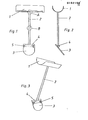
Figuren 1 bis 3 eine Abduktionsschiene in drei verschiedenen Seitenansichten,Figuren 4 bis 6 verschiedene Ansichten eines die Abduktionsschiene nach denFiguren 1 bis 3 tragenden Patienten,Figur 7 die perspektivische Ansicht einer anderen Ausführungsform für eine erfindungsgemäße Abduktionsschiene,Figuren 8 und 9 zwei Seitenansichten einer geteilten und in der Länge veränderbaren Stütze,Figur 10 ein zwischen der Stütze und der Armauflage wirkendes Doppelscharniergelenk in perspektivischer Seitenansicht,Figur 11 die Seitenansicht eines Doppelscharniergelenkes nachFigur 10, jedoch mit relativ zueinander verstellbaren Gelenkachsen,Figur 12 ein Doppelscharniergelenk mit durch Federn zusammengehaltenen Gelenkkörpern in Seitenansicht,Figur 13 ein weiteres Ausführungsbeispiel der Erfindung undFiguren 14 und 15 eine spezielle Ausführungsform für ein Gelenk.
- FIGS. 1 to 3 an abduction splint in three different side views,
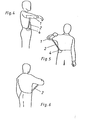
- FIGS. 4 to 6 different views of a patient carrying the abduction splint according to FIGS. 1 to 3,
- FIG. 7 shows the perspective view of another embodiment for an abduction splint according to the invention,
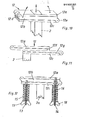
- FIGS. 8 and 9 show two side views of a divided and length-adjustable support,
- FIG. 10 is a perspective side view of a double hinge joint acting between the support and the armrest,
- FIG. 11 shows the side view of a double hinge joint according to FIG. 10, but with joint axes that can be adjusted relative to one another,
- FIG. 12 is a side view of a double hinge joint with joint bodies held together by springs,
- Figure 13 shows another embodiment of the invention and
- Figures 14 and 15 a special embodiment for a joint.
Die in den Figuren 1 bis 6 gezeigte Schiene hat einen relativ einfachen und somit kostengünstigen Aufbau. Sie besteht aus einer Armauflage 1 für den Unterarm, einer Stütze 2 in Form eines Stabes und aus am unteren Stützenende befindlichen Befestigungsmitteln, die bei diesem Beispiel als Platte 3 ausgebildet sind. An dieser Platte befindet sich ein Haken 4, über den eine mechanische Verbindung der Schiene mit einem Bekleidungsstück hergestellt wird, indem entsprechend den Figuren 4 bis 6 die Platte 3 im Bereich der Taille des Patienten so von oben zwischen Hose und Hemd bzw. Unterbekleidung geschoben wird, daß der Haken 4 über den Gürtel oder den Hosenbund greift.The rail shown in Figures 1 to 6 has a rela tiv simple and therefore inexpensive construction. It consists of an
In der Platte 3 können auch ösen oder Schlitze 5 vorgesehen werden, durch die ein mit einem Verschluß versehener Gurt oder Gürtel gesteckt wird, der um die Taille gelegt wird und die Platte 3 in der vorgesehenen Position festlegt. Im übrigen kann die Platte auch in Anpassung an die Körperform gewölbt sein, so daß sie beim Tragen nicht drückt und die einwirkende Stützkraft gleichmäßig auf den Anlagebereich am Körper verteilt.Loops or
Bei der Abduktionsschiene nach Figur 7 besteht die Armauflage aus dem Unterarmteil 1 und einem Oberarmteil 6, während die unten an der Stütze 2 vorgesehenen Befestigungsmittel in an sich bekannter Weise aus einem verschließbaren Gurt 7 bestehen, der im Bereich der Taille um den Körper des Patienten gelegt werden kann. Auch in diesem Fall wird die durch den abgestützten Arm und die Schiene bedingte Last wie beim vorher beschriebenen Beispiel im wesentlichen an einer Stelle seitlich auf den Körper übertragen.In the abduction splint according to FIG. 7, the armrest consists of the
An den mit den Kreisen A angedeuteten Stellen können Scharniergelenke zwischen der Stütze 2 und der Armauflage 1 einerseits und dem Gurt 7 als Befestigungsmittel andererseits angeordnet werden. Hierauf wird später noch näher eingegangen. Weiterhin kann die als Stützstab ausgebildete Stütze 2 an dem durch den Kreis B angegebenen Bereich unterteilt und wie in den Figuren 8 und 9 dargestellt ausgebildet sein, um eine Längenänderung der Stütze durchführen zu können. Die Bereich A und B sind übrigens auch in der Figur 1 zu finden, so daß auch das dort dargestellte Ausführungsbeispiel hinsichtlich eines Scharniergelenkes und einer Längenverstellung der Stütze in gleicher Weise ausgebildet werden kann, wie es nachfolgend im Zusammenhang mit den anderen Ausführungsformen beschrieben wird.At the points indicated by the circles A, hinge joints can be arranged between the
Eine Längenänderung der Stütze 2 kann so erreicht werden, daß den Figuren 8 und 9 entsprechend zwei Stützstabteile 2a, 2b z.B. teleskopisch ineinandergreifen und eine zwischen ihnen eingesetzte Druckfeder 8 so wirkt, daß der obere, die Armauflage 1, 6 tragende Stützstabteil 2a gegen und mit Wirkung dieser Feder axial und relativ zum unteren, hierbei feststehenden Stützstabteil 2b bewegt werden kann. Dabei greift das obere Ende der Feder 8 am unteren Ende des Stützstabteiles 2a und das untere Federende an einem Anschlag 9 an, der geführt im feststehenden Stützstabteil 2b verstellt und mit einer Schraube 10 am Stützstabteil 2b fixiert werden kann. Diese Schraube greift mit ihrem Gewindeschaft frei durch einen Längsschlitz 11 und ist in ein Gewindeloch des Anschlages 9 geschraubt, so daß beim Festdrehen der Schraube der Anschlag 9 mit der inneren Wandung des Stützstabteiles 2b verklemmt wird. Es ist offensichtlich, daß mit der jeweiligen axialen Position des Anschlages 9 die wirksame Länge der Stütze 2 eingestellt werden kann.A change in length of the
Mit einer Abduktionsschiene dieser Art kann der Patient das Anspreizen und Abspreizen des Armes üben, wobei die Feder 8 die Kraft bestimmt, die zum einen beim Anspreizen zu überwinden ist und zum anderen eine nachfolgende Abspreizbewegung unterstützen wird. Falls allerdings die beiden Stützstabteile 2a, 2b unter Ausschalten der Federwirkung starr verbunden werden sollen, wird eine weitere Schraube 10aangezogen, so daß der ebenfalls durch den Längsschlitz 11 verlaufende und im Stützstabteil 12a verschraubte Gewindeschaft diesen mit dem Stützstabteil 2b verklemmt.With an abduction splint of this type, the patient can practice spreading and spreading the arm, the
Wie bereits erwähnt wurde, kann der Patient zur Durchführung von Bewegungsübungen den Arm ohne weiteres und ungehindert um ein gewisses Maß nach vorn und hinten bewegen, wobei die Armauflage 1 im wesentlichen auf einem Kreisbogen um das untere Ende der Stütze bzw. des Stützstabes 2 verschwenkt wird. Neben der weiteren und schon beschriebenen Möglichkeit des Anspreizens und Abspreizens des Armes ergeben sich weitere Freiheitsgrade für die Armbewegungen, wenn zwischen der Armauflage 1 und dem seitlich an der Taille befindlichen Befestigungspunkt zumindest ein Scharniergelenk, insbesondere wenigstens ein Doppelscharniergelenk, vorgesehen wird, das eine Schwenkbewegung der Armauflage relativ zur Stütze 2 und/oder eine Schwenkbewegung der Stütze 2 relativ zu den Befestigungsmitteln 3, 7 zuläßt. Die Kreise A in den Figuren 1 und 7 deuten Stellen an, wo solche Scharniergelenke angeordnet werden können, während die Figur 13 hierfür ein praktisches Ausführungsbeispiel darstellt.As already mentioned, the patient can move the arm forwards and backwards to a certain extent without difficulty and without hindrance, the
In der Figur 10 ist ein Doppelscharniergelenk 12 gezeigt, das am oberen Ende der Stütze 2 und vorzugsweise unmittelbar unter der nicht weiter dargestellten Armauflage 1 befestigt ist. Das Scharniergelenk besteht aus drei plattenförmigen Gelenkkörpern, und zwar aus dem oberen, starr an der Armauflage 1 befestigten Gelenkkörper 12a, aus dem mittleren Gelenkkörper 12b und dem unteren Gelenkkörper 12c, an dem unten die Stütze 2 starr befestigt ist. Im übrigen stehen diese Gelenkkörper über die beiden Achsen 12d undFIG. 10 shows a
12e so in Verbindung, daß die durch die Pfeile (Figur 10) angegebenen Bewegungen und Verstellmöglichkeiten gegeben sind. Der Gelenkkörper 12a kann also entgegengesetzt zum Uhrzeigersinn um die Achse 12d verschwenkt werden, während die Gelenkkörper 12a, 12b gemeinsam um die Achse 12e im Uhrzeigersinn verschwenkbar sind. Weiterhin kann der Gelenkkörper 12a in Parallellager zum feststehenden Gelenkkörper 12c angehoben werden. Schließlich können sich diese Verstellbewegungen je nach Richtung einer willkürlichen Armbewegung auch überlagern und in umgekehrter Richtung erfolgen, bis die Gelenkkörper wieder die dargestellte stabile Lage einnehmen. Diese Lage ist deshalb stabil, weil die beiden parallelen Gelenkachsen 12d, 12e exzentrisch zur Wirklinie der Stütze 2 liegen.12e in such a way that the movements and adjustment possibilities indicated by the arrows (FIG. 10) are given. The
Die zum Aufklappen der Teile des Scharniergelenkes 12 erforderliche und von den Arm- sowie Schultermuskeln aufzubringende Kraft kann im übrigen auch in Abhängigkeit von der jeweils gewünschten Schwenkrichtung des Armes eingestellt werden, wenn die beiden Gelenkachsen relativ zueinander und/oder relativ zur Wirklinie bzw. gedachten Verlängerung der Stütze 2 verstellt werden können. In diesem Fall kann der mittlere Gelenkkörper geteilt werden, so daß das Gelenk 12 gemäß Figur 11 aus zwei Einzelscharnieren mit je zwei Gelenkkörpern besteht, wobei die beiden mittleren benachbarten Gelenkkörper 12f, 12g zwar miteinander verbunden sind, aber relativ zueinander verschoben werden können. Dies kann beispielsweise durch einen formschlüssigen Führungseingriff dieser beiden Gelenkkörper erreicht werden.The force required to open the parts of the hinge joint 12 and to be exerted by the arm and shoulder muscles can also be set as a function of the respectively desired pivoting direction of the arm if the two joint axes are relative to one another and / or relative to the line of action or imaginary extension the
Die Kraft zum Aufklappen des Scharniergelenkes kann auch durch Federn beeinflußt und eingestellt werden. Hierzu zeigt die Figur 12 eine Lösung. Ein Gewindebolzen 13 ist durch ein Langloch des unteren Gelenkkörpers 12c geführt und am mittleren Gelenkkörper 12b angelenkt, während ein am oberen Gelenkkörper 12a angelenkter Gewindebolzen 14 durch Langlöcher der Gelenkkörper 12c, 12d verläuft. Auf diesen Gewindebolzen sitzen konzentrisch Druckfedern 15, 16, die sich nach der Darstellung mit ihren oberen Enden am Gelenkkörper 12c und mit ihren unteren Enden an Flügelmuttern abstützen.The force to open the hinge joint can also be influenced and adjusted by springs. Figure 12 shows a solution for this. A threaded
Mit den Flügelmuttern 17, 18 kann von Hand die Druckkraft eingestellt werden, mit der die Gelenkkörper zusammengehalten werden und die beim üben von Armbewegungen von der Muskelkraft aufgebracht werden muß, um bei Schwenkbewegungen des Armes den Gelenkkörper 12a entgegengesetzt dem Uhrzeigersinn vom Gelenkkörper 12b oder diesen im Uhrzeigersinn vom Gelenkkörper 12c durch Verschwenken anheben zu können.The
Die Figur 13 zeigt eine Abduktionsschiene, bei der am oberen und unteren Ende der Stütze 2 jeweils ein Scharniergelenk 12 vorgesehen ist. Die eingezeichneten Pfeile geben die Richtungen an, in denen die Stütze 2 mit dem unteren Scharniergelenk 12 verschwenkt und der Unterarmteil 1 der Armauflage um das oben an der Stütze 2 befindliche Scharniergelenk 12 verschwenkt und relativ zur Stütze 2 angehoben werden kann.FIG. 13 shows an abduction rail, in which a hinge joint 12 is provided at the upper and lower end of the
In den Figuren 14 und 15 ist eine spezielle Ausführungsform für ein Gelenk dargestellt, mit dem die Stütze am unteren Ende mit der Platte 3 lösbar verbunden werden kann. Es handelt sich hierbei um ein Kugelgelenk, dessen Kugel 19 über einen Steg 20 mit der Stütze 2 verbunden ist. Die Kugel ruht so in einer Mulde des an der Platte 3 befestigten Halters 21, daß die Stütze mit der Armauflage relativ zur Platte und somit zum Körper des Patienten verschwenkt werden kann. Der aus elastischem bzw. federndem MaterialFIGS. 14 and 15 show a special embodiment for a joint with which the support at the lower end can be detachably connected to the
bestehende Halter 21 hat zwei Arme 21a, 21b, zwischen denen ein oben offener Einführungsschlitz 22 ausgebildet ist, in den der Steg 20 paßt. Gemäß Figur 15 hat der Halter am oberen Ende einen Abstand zur Platte 3, der geringer als der Durchmesser der Gelenkkugel 19 ist.existing
Die Gelenkverbindung wird so hergestellt, daß die Gelenkkugel 19 mit dem auf den Schlitz 22 ausgerichteten Steg 20 oben am Halter 21 angesetzt und nach unten gedrückt wird, so daß die Kugel unter Abspreizen des Halters von der Platte 3 in die erwähnte Mulde gelangt, wobei der Steg durch den Schlitz nach unten geführt wird.The articulated connection is made so that the articulated
Abschließend wird darauf hingewiesen, daß erforderlichenfalls auch der Oberarmteil 6 der Armauflage in seiner Position verstellt werden kann. Weiterhin besteht die Möglichkeit, an den Teilen 1 und 6 der Armauflage Gurte oder Bänder anzubringen, mit denen der Unter- und Oberarm auf den Armteilen 1 und 6 befestigt werden kann.Finally, it is pointed out that, if necessary, the position of the upper arm part 6 of the armrest can also be adjusted. There is also the possibility of attaching straps or straps to
Claims (15)
Priority Applications (1)
| Application Number | Priority Date | Filing Date | Title |
|---|---|---|---|
| AT86101779T ATE63053T1 (en) | 1985-02-18 | 1986-02-12 | ABDUCTION BRACKET TO RELIEVE THE SHOULDER JOINT. |
Applications Claiming Priority (2)
| Application Number | Priority Date | Filing Date | Title |
|---|---|---|---|
| DE3505528 | 1985-02-18 | ||
| DE19853505528 DE3505528A1 (en) | 1985-02-18 | 1985-02-18 | ABDUCTION RAIL TO RELEASE THE SHOULDER JOINT |
Publications (3)
| Publication Number | Publication Date |
|---|---|
| EP0192181A2 true EP0192181A2 (en) | 1986-08-27 |
| EP0192181A3 EP0192181A3 (en) | 1987-09-16 |
| EP0192181B1 EP0192181B1 (en) | 1991-05-02 |
Family
ID=6262818
Family Applications (1)
| Application Number | Title | Priority Date | Filing Date |
|---|---|---|---|
| EP86101779A Expired - Lifetime EP0192181B1 (en) | 1985-02-18 | 1986-02-12 | Abduction splint for the relief of the shoulder joint |
Country Status (3)
| Country | Link |
|---|---|
| EP (1) | EP0192181B1 (en) |
| AT (1) | ATE63053T1 (en) |
| DE (2) | DE3505528A1 (en) |
Cited By (6)
| Publication number | Priority date | Publication date | Assignee | Title |
|---|---|---|---|---|
| FR2602674A1 (en) * | 1986-08-14 | 1988-02-19 | Dumoutier Gerard | ORTHOPEDIC BRACE |
| EP0727198A1 (en) * | 1995-02-16 | 1996-08-21 | Protectair Limited | Improvement to orthoses for the upper body |
| US9204989B2 (en) | 2013-09-06 | 2015-12-08 | Universite De Montreal | Dynamic shoulder orthosis with rehabilitating adduction |
| US9918854B2 (en) | 2011-03-16 | 2018-03-20 | Smith & Nephew, Inc. | Compound angle implant |
| CN113164275A (en) * | 2018-11-05 | 2021-07-23 | 奥托博克欧洲股份两合公司 | Device for supporting at least one arm of a user |
| JP2022054479A (en) * | 2020-09-27 | 2022-04-07 | 太陽パーツ株式会社 | Support wear |
Families Citing this family (2)
| Publication number | Priority date | Publication date | Assignee | Title |
|---|---|---|---|---|
| DE19911834A1 (en) * | 1999-03-17 | 2000-10-05 | Felix Becker | Arm support, to support under arm of patient in raised position; has upper arm rest hinged top of telescopic position, that can be moved to desired angle by handle using one hand only |
| DE102017112436B4 (en) * | 2017-06-06 | 2019-05-29 | Ottobock Se & Co. Kgaa | Device for supporting at least one arm of a user |
Citations (4)
| Publication number | Priority date | Publication date | Assignee | Title |
|---|---|---|---|---|
| US1295297A (en) * | 1917-10-20 | 1919-02-25 | John Rollin French | Surgical splint. |
| DE582933C (en) * | 1932-01-03 | 1933-08-25 | Heinrich C Ulrich | Arm support rail with shoulder joint to be attached to the body |
| US3952733A (en) * | 1975-04-23 | 1976-04-27 | Williams Ester B | Arm support |
| US4241731A (en) * | 1978-05-11 | 1980-12-30 | Pauley James H | Universal arm support |
Family Cites Families (4)
| Publication number | Priority date | Publication date | Assignee | Title |
|---|---|---|---|---|
| US2661000A (en) * | 1951-06-25 | 1953-12-01 | William E Gazeley | Surgical splint |
| SE418452B (en) * | 1978-02-08 | 1981-06-09 | Holmgren Ortoped | CONTROL FOR UNDERWEAR ORTHOS AND SIMILAR |
| JPS5540211A (en) * | 1978-09-13 | 1980-03-21 | Toyota Motor Corp | Exhaust gas recirculating control valve for diesel engine |
| DE3030712A1 (en) * | 1980-08-14 | 1982-03-18 | Blanc Gmbh & Co, 7519 Oberderdingen | Support rail for shoulder abduction treatment - has lockable arm-rotation joint between upper arm rail and elbow joint |
-
1985
- 1985-02-18 DE DE19853505528 patent/DE3505528A1/en active Granted
-
1986
- 1986-02-12 AT AT86101779T patent/ATE63053T1/en not_active IP Right Cessation
- 1986-02-12 DE DE8686101779T patent/DE3678974D1/en not_active Expired - Lifetime
- 1986-02-12 EP EP86101779A patent/EP0192181B1/en not_active Expired - Lifetime
Patent Citations (4)
| Publication number | Priority date | Publication date | Assignee | Title |
|---|---|---|---|---|
| US1295297A (en) * | 1917-10-20 | 1919-02-25 | John Rollin French | Surgical splint. |
| DE582933C (en) * | 1932-01-03 | 1933-08-25 | Heinrich C Ulrich | Arm support rail with shoulder joint to be attached to the body |
| US3952733A (en) * | 1975-04-23 | 1976-04-27 | Williams Ester B | Arm support |
| US4241731A (en) * | 1978-05-11 | 1980-12-30 | Pauley James H | Universal arm support |
Cited By (7)
| Publication number | Priority date | Publication date | Assignee | Title |
|---|---|---|---|---|
| FR2602674A1 (en) * | 1986-08-14 | 1988-02-19 | Dumoutier Gerard | ORTHOPEDIC BRACE |
| EP0264303A1 (en) * | 1986-08-14 | 1988-04-20 | Dumoutier, Gérard Michel | Orthopaedic splint |
| EP0727198A1 (en) * | 1995-02-16 | 1996-08-21 | Protectair Limited | Improvement to orthoses for the upper body |
| US9918854B2 (en) | 2011-03-16 | 2018-03-20 | Smith & Nephew, Inc. | Compound angle implant |
| US9204989B2 (en) | 2013-09-06 | 2015-12-08 | Universite De Montreal | Dynamic shoulder orthosis with rehabilitating adduction |
| CN113164275A (en) * | 2018-11-05 | 2021-07-23 | 奥托博克欧洲股份两合公司 | Device for supporting at least one arm of a user |
| JP2022054479A (en) * | 2020-09-27 | 2022-04-07 | 太陽パーツ株式会社 | Support wear |
Also Published As
| Publication number | Publication date |
|---|---|
| EP0192181A3 (en) | 1987-09-16 |
| DE3505528C2 (en) | 1987-10-15 |
| DE3505528A1 (en) | 1986-08-21 |
| EP0192181B1 (en) | 1991-05-02 |
| DE3678974D1 (en) | 1991-06-06 |
| ATE63053T1 (en) | 1991-05-15 |
Similar Documents
| Publication | Publication Date | Title |
|---|---|---|
| DE3710233C2 (en) | ||
| DE102005025159A1 (en) | Artificial leg with ischial support | |
| EP0362528B1 (en) | Abduction pillow | |
| DE60205192T2 (en) | Joint splint for controlling and regulating the flexion of the knee joint | |
| WO2021094159A1 (en) | Device for supporting the back of a user | |
| DE3235134C2 (en) | Orthopedic foot splint with swiveling shoe mounting plates | |
| WO2021094220A1 (en) | Orthopaedic device for supporting the lower back of a user | |
| EP0192181B1 (en) | Abduction splint for the relief of the shoulder joint | |
| DE2152408B2 (en) | PHYSIOLOGICAL KNEE FOR A TUBULAR SKELETON PROSTHESIS | |
| DE19652416A1 (en) | Method for supporting trunk in tilted forward position | |
| DE2724586A1 (en) | Orthopaedic knee joint cage - has specially shaped upper and lower frames connected by swinging links with straps attached | |
| DE3436120C1 (en) | Training device for training the thigh and calf muscles | |
| CH650658A5 (en) | Therapy couch | |
| EP1292366A2 (en) | Device used for therapy and for exercising the joints of the human body | |
| DE1147711B (en) | Abduction splint | |
| DE60209459T2 (en) | Scapula / humerus rehabilitation unit | |
| DE10152769B4 (en) | Abductor and adductor training devices for strengthening the muscles and for selective control of the muscle motor | |
| EP3873390B1 (en) | Knee brace | |
| DE4313494A1 (en) | Device for lifting a bed-ridden individual or an individual of impaired mobility | |
| DE4108863C2 (en) | Orthosis to stabilize the lower extremities | |
| DE3915079C2 (en) | Physical training device | |
| DE4415604B4 (en) | Orthosis for immobilization of the lumbar spine | |
| DE102021131813A1 (en) | Hip abduction orthosis and orthosis system | |
| DE2532285C2 (en) | Lower leg support to be set up on a lying surface | |
| DE102021120725A1 (en) | Device for treating the human spine |
Legal Events
| Date | Code | Title | Description |
|---|---|---|---|
| PUAI | Public reference made under article 153(3) epc to a published international application that has entered the european phase |
Free format text: ORIGINAL CODE: 0009012 |
|
| AK | Designated contracting states |
Kind code of ref document: A2 Designated state(s): AT BE CH DE FR GB IT LI NL SE |
|
| PUAL | Search report despatched |
Free format text: ORIGINAL CODE: 0009013 |
|
| RHK1 | Main classification (correction) |
Ipc: A61F 5/04 |
|
| AK | Designated contracting states |
Kind code of ref document: A3 Designated state(s): AT BE CH DE FR GB IT LI NL SE |
|
| 17P | Request for examination filed |
Effective date: 19880114 |
|
| RAP1 | Party data changed (applicant data changed or rights of an application transferred) |
Owner name: JACOBSEN, UWE, DR. MED. |
|
| RIN1 | Information on inventor provided before grant (corrected) |
Inventor name: JACOBSEN, UWE, DR. MED. |
|
| 17Q | First examination report despatched |
Effective date: 19890824 |
|
| GRAA | (expected) grant |
Free format text: ORIGINAL CODE: 0009210 |
|
| AK | Designated contracting states |
Kind code of ref document: B1 Designated state(s): AT BE CH DE FR GB IT LI NL SE |
|
| PG25 | Lapsed in a contracting state [announced via postgrant information from national office to epo] |
Ref country code: IT Free format text: LAPSE BECAUSE OF FAILURE TO SUBMIT A TRANSLATION OF THE DESCRIPTION OR TO PAY THE FEE WITHIN THE PRE;WARNING: LAPSES OF ITALIAN PATENTS WITH EFFECTIVE DATE BEFORE 2007 MAY HAVE OCCURRED AT ANY TIME BEFORE 2007. THE CORRECT EFFECTIVE DATE MAY BE DIFFERENT FROM THE ONE RECORDED.SCRIBED TIME-LIMIT Effective date: 19910502 Ref country code: SE Effective date: 19910502 Ref country code: NL Effective date: 19910502 Ref country code: FR Effective date: 19910502 Ref country code: BE Effective date: 19910502 Ref country code: GB Effective date: 19910502 |
|
| REF | Corresponds to: |
Ref document number: 63053 Country of ref document: AT Date of ref document: 19910515 Kind code of ref document: T |
|
| REF | Corresponds to: |
Ref document number: 3678974 Country of ref document: DE Date of ref document: 19910606 |
|
| EN | Fr: translation not filed | ||
| NLV1 | Nl: lapsed or annulled due to failure to fulfill the requirements of art. 29p and 29m of the patents act | ||
| GBV | Gb: ep patent (uk) treated as always having been void in accordance with gb section 77(7)/1977 [no translation filed] | ||
| PG25 | Lapsed in a contracting state [announced via postgrant information from national office to epo] |
Ref country code: AT Effective date: 19920212 |
|
| PG25 | Lapsed in a contracting state [announced via postgrant information from national office to epo] |
Ref country code: CH Effective date: 19920229 Ref country code: LI Effective date: 19920229 |
|
| PLBE | No opposition filed within time limit |
Free format text: ORIGINAL CODE: 0009261 |
|
| STAA | Information on the status of an ep patent application or granted ep patent |
Free format text: STATUS: NO OPPOSITION FILED WITHIN TIME LIMIT |
|
| 26N | No opposition filed | ||
| REG | Reference to a national code |
Ref country code: CH Ref legal event code: PL |
|
| PGFP | Annual fee paid to national office [announced via postgrant information from national office to epo] |
Ref country code: DE Payment date: 19940426 Year of fee payment: 9 |
|
| PG25 | Lapsed in a contracting state [announced via postgrant information from national office to epo] |
Ref country code: DE Effective date: 19951101 |