EP0192144A2 - Dispositif d'échange d'énergie et/ou de matières entre des fines et un fluide - Google Patents
Dispositif d'échange d'énergie et/ou de matières entre des fines et un fluide Download PDFInfo
- Publication number
- EP0192144A2 EP0192144A2 EP86101621A EP86101621A EP0192144A2 EP 0192144 A2 EP0192144 A2 EP 0192144A2 EP 86101621 A EP86101621 A EP 86101621A EP 86101621 A EP86101621 A EP 86101621A EP 0192144 A2 EP0192144 A2 EP 0192144A2
- Authority
- EP
- European Patent Office
- Prior art keywords
- reactor
- channels
- discharge
- levels
- shaft
- Prior art date
- Legal status (The legal status is an assumption and is not a legal conclusion. Google has not performed a legal analysis and makes no representation as to the accuracy of the status listed.)
- Granted
Links
Images


Classifications
-
- C—CHEMISTRY; METALLURGY
- C04—CEMENTS; CONCRETE; ARTIFICIAL STONE; CERAMICS; REFRACTORIES
- C04B—LIME, MAGNESIA; SLAG; CEMENTS; COMPOSITIONS THEREOF, e.g. MORTARS, CONCRETE OR LIKE BUILDING MATERIALS; ARTIFICIAL STONE; CERAMICS; REFRACTORIES; TREATMENT OF NATURAL STONE
- C04B2/00—Lime, magnesia or dolomite
- C04B2/10—Preheating, burning calcining or cooling
- C04B2/12—Preheating, burning calcining or cooling in shaft or vertical furnaces
-
- B—PERFORMING OPERATIONS; TRANSPORTING
- B01—PHYSICAL OR CHEMICAL PROCESSES OR APPARATUS IN GENERAL
- B01J—CHEMICAL OR PHYSICAL PROCESSES, e.g. CATALYSIS OR COLLOID CHEMISTRY; THEIR RELEVANT APPARATUS
- B01J8/00—Chemical or physical processes in general, conducted in the presence of fluids and solid particles; Apparatus for such processes
- B01J8/08—Chemical or physical processes in general, conducted in the presence of fluids and solid particles; Apparatus for such processes with moving particles
- B01J8/12—Chemical or physical processes in general, conducted in the presence of fluids and solid particles; Apparatus for such processes with moving particles moved by gravity in a downward flow
- B01J8/125—Chemical or physical processes in general, conducted in the presence of fluids and solid particles; Apparatus for such processes with moving particles moved by gravity in a downward flow with multiple sections one above the other separated by distribution aids, e.g. reaction and regeneration sections
-
- F—MECHANICAL ENGINEERING; LIGHTING; HEATING; WEAPONS; BLASTING
- F27—FURNACES; KILNS; OVENS; RETORTS
- F27B—FURNACES, KILNS, OVENS, OR RETORTS IN GENERAL; OPEN SINTERING OR LIKE APPARATUS
- F27B15/00—Fluidised-bed furnaces; Other furnaces using or treating finely-divided materials in dispersion
-
- F—MECHANICAL ENGINEERING; LIGHTING; HEATING; WEAPONS; BLASTING
- F28—HEAT EXCHANGE IN GENERAL
- F28C—HEAT-EXCHANGE APPARATUS, NOT PROVIDED FOR IN ANOTHER SUBCLASS, IN WHICH THE HEAT-EXCHANGE MEDIA COME INTO DIRECT CONTACT WITHOUT CHEMICAL INTERACTION
- F28C3/00—Other direct-contact heat-exchange apparatus
- F28C3/10—Other direct-contact heat-exchange apparatus one heat-exchange medium at least being a fluent solid, e.g. a particulate material
- F28C3/12—Other direct-contact heat-exchange apparatus one heat-exchange medium at least being a fluent solid, e.g. a particulate material the heat-exchange medium being a particulate material and a gas, vapour, or liquid
-
- Y—GENERAL TAGGING OF NEW TECHNOLOGICAL DEVELOPMENTS; GENERAL TAGGING OF CROSS-SECTIONAL TECHNOLOGIES SPANNING OVER SEVERAL SECTIONS OF THE IPC; TECHNICAL SUBJECTS COVERED BY FORMER USPC CROSS-REFERENCE ART COLLECTIONS [XRACs] AND DIGESTS
- Y02—TECHNOLOGIES OR APPLICATIONS FOR MITIGATION OR ADAPTATION AGAINST CLIMATE CHANGE
- Y02P—CLIMATE CHANGE MITIGATION TECHNOLOGIES IN THE PRODUCTION OR PROCESSING OF GOODS
- Y02P40/00—Technologies relating to the processing of minerals
- Y02P40/40—Production or processing of lime, e.g. limestone regeneration of lime in pulp and sugar mills
Definitions
- the invention relates to a method and a device for carrying out an energy and / or mass exchange between or on small-grain solids or a liquid medium and a fluid medium, the fluid medium through a shaft-like reactor which is filled with the small-grain solid or the small grained solid or the liquid medium migrates, is passed.
- Methods and devices of the aforementioned type are e.g. needed for burning limestone, dolomite, magnesite, plaster and the like.
- the methods previously used for this purpose use i.a. also shaft ovens. Due to the mode of operation with a top-down material flow and a bottom-up gas stream (which also includes cooling air blown in at the base of the furnace), there is a division into the cooling, combustion and preheating zones. For a good and trouble-free operation it is important, in addition to a narrowly graded grain structure and a uniform loading and emptying of the furnace, that the air is evenly distributed over the furnace cross-section and that the right size ratio and the right mix of limestone to coke is maintained. Although desirable, small grain solids cannot be processed in this known manner because of the requirement
- the device used here is the so-called cross-flow furnace, in which the solid material is treated in a narrow bed between gas-permeable walls in a cross-flow with hot gas or air.
- the cross-flow furnace for lime or dolomite burning, large inflow areas are required in order to achieve a uniform soft fire with the appropriate throughput.
- the furnace aisle with a grain class in the range of approx. 10/20 to 40/60 mm has proven to be expedient to reverse the flow direction at least once in order to compensate for the difference in fire caused by the one-sided inflow.
- the cross-flow furnace has heights that are not inferior to those of other shaft furnaces and that use material with a grain size below the above. do not allow lower limit.
- the invention is therefore based on the object of providing a method and a device which improve energy and / or mass transfer between or on granular solids and a fluid medium, e.g. a gas, fuel gas or a liquid, in particular allow small-grained solids, which could not be treated according to the conventional shaft furnace principle, to make said exchange processes accessible.
- a fluid medium e.g. a gas, fuel gas or a liquid
- the fluid medium is preferably a gas, fuel gas, steam or mixtures thereof or a liquid, e.g. Air, CO., Nitrogen, flue gas, water, a suspension, organic liquid and the like.
- the distance between an introduction and the next adjacent discharge plane is preferably not less than about 5 to 20 times and not more than about 100 to 200 times the grain diameter of the solid.
- the distance depends e.g. according to the grain size of the feed material, a smaller distance being selected for smaller grain sizes.
- These levels are each formed by a plurality of lines for the fluid medium, which are spaced in the respective level so that the small-grained solid can, if desired, pass between them.
- the tubes or channels are preferably perforated or open at least on one long side.
- At least one discharge level is assigned to each supply level.
- An introduction level and the two associated discharge levels form an energy and / or mass transfer unit.
- One or more of these units can be combined to form a flow area, a plurality of these flow areas in turn can be connected in series and / or in parallel.
- Another fluid of the same physical state can flow through one or more flow areas that form a separate unit in the reactor.
- a shaft-like reactor is therefore constructed according to the invention with the aid of devices for distributing a fluid medium, e.g. Tubes or ducts, divided into discharge and discharge levels, so that normally each discharge level is followed by two parallel discharge levels and the fluid medium after the tubes or channels have been soaked in the discharge level essentially only the layers of granular material between this discharge level and the subsequent discharge levels Solid has to migrate.
- a fluid medium e.g. Tubes or ducts
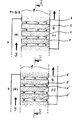
- FIG. 1 - The structure of a device for carrying out the method according to the invention is shown schematically in FIG. 1 - (longitudinal section).
- a material shaft 1 shaft furnace, packed column, reactor or the like
- an inlet shaft 3 (+) and an outlet shaft 4 (-) for the fluid medium are shown schematically in FIG. 1 - (longitudinal section).
- These shafts can in principle be designed in various forms adapted to the respective intended use, for example in the form of rectangular shafts, tubes, etc.
- the fluid medium flows from the inlet shaft 3 via the inlet levels 2 through the material being dispensed and is determined according to the desired energy and / or or mass transfer via the discharge levels 2 'and the discharge shaft 4.
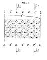
- FIG. 2 shows the principle according to the invention as an overflow system.
- the levels of the inlet 2 or outlet levels 2 ' are each arranged parallel to the longitudinal axis.
- the fluid medium is guided into the introduction levels 2 via the inlet shaft, then flows transversely to the longitudinal axis to the corresponding outlet levels 2' and is discharged via the outlet shaft.
- the flow conditions in the method according to the invention are shown in detail in FIGS. 3 and 4, with FIG. 3 showing the flow conditions in the longitudinal flow arrangement according to FIG. 1 and FIG. 4 showing the flow conditions in the cross flow arrangement according to FIG. 2.
- the inlet 2 or outlet planes 2 ' are preferably designed in the form of perforated tubes or channels which are open at least on one long side.
- the shape is, however, not restricted to this, but rather is adapted to the respective intended use. Examples are shown in FIG. 5.
- the optimal design, dimensioning and arrangement are related to the grain diameter, the dimensions of the material shaft, the flow volume, the method and the like and are easily apparent to the person skilled in the art.
- the filling material can be a continuous, resting or moving column of bulk goods.
- the energy and / or mass exchange between the fluid medium and (or on) the bulk material column can take place or the reactor is loaded in the longitudinal axis with a further liquid medium or a suspension, which is involved in the energy and / or mass exchange with the laterally introduced fluid medium are involved.
- the process can also be applied using pressure up to approx. 10 bar. In general, this is not necessary, but it is sufficient to use the additional form which is low to flow through the device and to overcome the flow resistance caused by the grain.
- the method according to the invention can be used universally and is suitable e.g. also for wet or dry removal of pollutants from flue gases, dust separation, separation of mists, as a heat exchanger, evaporative cooler as well as for sighting or classification processes.
- the inlet shaft 3 and the outlet shaft 4 have a depth of 0.2 m, a width of 1 m and a height of 2 m.
- the channel length is 40 cm, the leg height 1 cm and the gable height and gable width 3 cm.
- Drying takes place in the longitudinal flow arrangement, whereby approx. 4500 - 6000 Nm 3 / h hot gas at a temperature of approx. 500 - 700 ° C are required.
- the gas velocity is 0.2 m / sec, based on the empty shaft between an inflow level and an outflow level and under normal conditions.
- the material speed is approx. 4 - 5 mm / sec, so that there is a dwell time of approx. 7 min, based on a bulk density of 1.5.
- Limestone chippings can also be dried when the levels are arranged vertically according to FIG. 2. Dimensions, shape of the channels and spacing of the levels remain the same, only the vertical spacing of the channels is reduced to 6 cm.
- Example 1 The device described in Example 1 is used for dedusting a furnace exhaust gas of approximately 200 ° C.
- a quartz round gravel or a stone chip of a narrow grain size with a grain diameter of 2, 3 or 4 mm is used as a filter.
- the fifter material is cleaned outside the material chute.
- the material shaft has a depth of 0.8 m and a width of 1.2 m.
- the inlet and outlet shafts have a depth of 0.4 m and a width of 1.2 m.
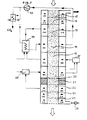
- the material shaft is divided into a preheating zone 15, 16, 17, a burning zone 18, 19, 20 and a cooling zone 22, 23, 2 4 .
- the preheating zone comprises a total of 10 exchange units - (3+ 3 + 4 ) with a total height of approx. 260 cm.
- the firing zone consists of 25 exchange units (10 + 8 + 7) with a total height of approx. 454 cm.
- the cooling zone comprises a total of 10 exchange units (4 + 3 + 3) with a total height of approx. 214 cm.
- the distance between the inlet and outlet levels is 10 cm in the preheating zone and 8 cm in the firing and cooling zone.
- the channels of the inlet and outlet levels have the gable shape with side legs (shape 8 according to FIG. 5), the length being 80 cm.
- the clear gable height and the width of the channels are 4 cm and Thigh height 2 cm.
- the clear gable height and width is 6 cm and the leg height is 2 cm.
- 12 channels per level 11 full channels, 2 half channels on the sides) are used in the firing and cooling zone, the distance between the side legs being 6 cm and from center to center 10 cm.
- the preheating zone comprises 10 channels per level (9 full channels, 2 half channels on the sides), the distance from center to center being 1 2 cm and the distance between the side legs 6 cm
- a separate combustion and mixing chamber 25 is assigned to the flow area 18, 19, 20 of the combustion zone.
- the bulk of the fluid medium in this case air, is blown into the base of the furnace, for example with the aid of the caft blower 28. This means that the lowest combustion area has the lowest CO 2 partial pressure and the largest excess of air.
- the lowest firing zone area 20 serves to control the product properties (soft, medium or hard firing).
- the uppermost firing zone region 18 enables very hot gases to be supplied, the temperature being reduced rapidly without endangering the properties of the firing material.
- the process according to the invention has the advantage that the post-deacidification zone 21 always remains fully effective. The reason for this is that there is a very low pressure drop between the cooling zone 22 and the combustion zone area 20 and therefore CO 2 still formed with the small amounts of hot purge air can be constantly removed from the equilibrium without endangering the adiabatic cooling. Another advantage is the fact that the excess heat of the process exhaust gas can be removed at the extraction points 26 and 27.
- the dolomitic half-fire can be carried out using commercially available screenings (for example 0.8-1.5 mm, 1-2 mm and 2-4 mm) in the device described in Example 3, so that it is possible in one and the same To produce shaft furnace alternately dolomitic full fire and half fire. If necessary, however, it is sufficient to provide a 1-2 stage version of the firing zone. However, it is advisable to match the spacing of the levels and the channel dimensions to the grain size. In general, in cases where several sieves are used one after the other, the coarsest sieve determines the arrangement of the levels and channel dimensions. In this way, unlike in conventional shaft furnaces, it is possible to use a very wide combined belt.
- the firing temperature must not exceed 800 - 850 ° C in the case of a half-fire. At the same time, a CO 2 partial pressure of> 2 5 - 30% is required. This is achieved via a rolling gas circuit in the combustion area, in that process exhaust gas is removed by means of hot gas blowers at the extraction points 26 and 27 (FIG. 6) and fed to the corresponding combustion and mixing chambers.
- the device shown in FIG. 7 is used, which corresponds in structure to the device according to FIG. 6.
- the top firing zone 18 is indirectly heated as follows.
- the carrier gas CO required for energy transfer develops automatically as process exhaust gas Rolling gas withdrawn from the uppermost combustion zone 18, via the hot air blower 33 to a heat exchanger 34 and from there fed back to the combustion zone 18.
- CO can be branched off from the rolling gas circuit via the separator 35 and can be obtained as pure CO.
- the indirect heating is only shown for the combustion zone 18; however, all other combustion zones can also be heated indirectly.
- Indirect heating of the shaft furnace can also be carried out using H, 0 or H 2 O / CO 2 as the carrier gas. This has the advantage that the firing temperature is lowered and you can therefore work in very mild firing conditions. At the same time, a washed CO 2 is obtained as a by-product in this way
- This method can also be applied to double reactions of ErdaJka-Jicarbonaten with quartz and the like analogously to firing gypsum, desorption processes, such as Obtaining SO, by thermal cleavage of SO, on activated coke and the like, as well as on exothermic processes such as Use roasting and the like.
- the structure of a device for removing pollutants from flue gases corresponds in principle to the arrangement shown in FIG. 1, possibly also in FIG. 2.
- An adsorbent shaft of 100 m 'capacity with a base area of 10 mx 1 m comprises 50 exchange units. These are composed of 50 discharge levels 2 and 51 discharge levels 2 ', the distance between the levels being 10 cm.
- the discharge and discharge levels consist of channels in the form of gables with side legs according to shape 8 in FIG. 5.
- the channels have a length of 100 cm, a clear gable height and a width of 4 cm and a leg height of 2 cm.
- There are 125 channels per level (124 full channels, 2 half channels on the sides), the distance between the channels between the legs being 4 cm and from center to center 8 cm
- adsorbent for example prepared activated coke with a grain diameter of, for example 4 - 6 mm, or 2.5 - 4 mm for the SO 2 - or Use HX and NO x adsorption.
- Desorption analogous to Example 5
- cooling of the activated coke can also be carried out in the same material shaft on the basis of the principle according to the invention.
- a material shaft of approx. 2 m height, 1 m depth and any width comprises 5 horizontally arranged exchange units. According to the arrangement shown in FIG. 1, these are formed from entry and exit levels at a distance of 20 cm.
- the planes are formed by channels of shape 5 in FIG. 5. The radius of these half pipes is 3 cm, the length of the channels 100 cm and the distance of the channels in one plane from center to center 10 cm.
- Approx. 10 to 12 m '/ h water per m' cross-sectional area can be achieved.
- a flow of air of 0.1 to 0.4 m / seconds, based on the empty shaft, is sufficient for a mass ratio of air / water of approximately 0.5 to 1.5.
- This material shaft can, for example, be loaded with round gravel with a grain diameter of 8-12 mm or with Raschig rings and the like.
- the same arrangement can also be used for the removal of excess carbonic acid from water.
- the device required for this comprises at least two separate flow areas, which are blown alternately hot and cold.
- a flow area is represented by a material shaft (1 m deep; 2 m wide; approx. 2 m high) with five exchange units with a plane spacing of 0.2 m (corresponding to Fig. 1).
- the shape, dimensions and side distances of the channels correspond to the information given in Example 1.
- a round quartz gravel with a grain diameter of 2, 4 or 6 mm can be used as the heat exchanger.
- the gas velocity is approx. 0.1 m / sec, based on the empty shaft under normal conditions.
Landscapes
- Chemical & Material Sciences (AREA)
- Engineering & Computer Science (AREA)
- Organic Chemistry (AREA)
- Ceramic Engineering (AREA)
- Mechanical Engineering (AREA)
- General Engineering & Computer Science (AREA)
- Thermal Sciences (AREA)
- Physics & Mathematics (AREA)
- Dispersion Chemistry (AREA)
- Chemical Kinetics & Catalysis (AREA)
- Materials Engineering (AREA)
- Structural Engineering (AREA)
- Devices And Processes Conducted In The Presence Of Fluids And Solid Particles (AREA)
- Physical Or Chemical Processes And Apparatus (AREA)
- Furnace Details (AREA)
- Treating Waste Gases (AREA)
Priority Applications (1)
| Application Number | Priority Date | Filing Date | Title |
|---|---|---|---|
| AT86101621T ATE76182T1 (de) | 1985-02-07 | 1986-02-07 | Vorrichtung zur durchfuehrung eines energieund/oder stoffaustausches zwischen oder an kleinkoernigen feststoffen und einem fluiden medium. |
Applications Claiming Priority (2)
| Application Number | Priority Date | Filing Date | Title |
|---|---|---|---|
| DE19853504214 DE3504214A1 (de) | 1985-02-07 | 1985-02-07 | Verfahren und vorrichtung zur durchfuehrung eines energie- und/oder stoffaustausches zwischen oder an kleinkoernigen feststoffen und einem fluiden medium |
| DE3504214 | 1985-02-07 |
Publications (3)
| Publication Number | Publication Date |
|---|---|
| EP0192144A2 true EP0192144A2 (fr) | 1986-08-27 |
| EP0192144A3 EP0192144A3 (en) | 1988-01-20 |
| EP0192144B1 EP0192144B1 (fr) | 1992-05-13 |
Family
ID=6261946
Family Applications (1)
| Application Number | Title | Priority Date | Filing Date |
|---|---|---|---|
| EP86101621A Expired - Lifetime EP0192144B1 (fr) | 1985-02-07 | 1986-02-07 | Dispositif d'échange d'énergie et/ou de matières entre des fines et un fluide |
Country Status (3)
| Country | Link |
|---|---|
| EP (1) | EP0192144B1 (fr) |
| AT (1) | ATE76182T1 (fr) |
| DE (2) | DE3504214A1 (fr) |
Cited By (1)
| Publication number | Priority date | Publication date | Assignee | Title |
|---|---|---|---|---|
| CN100451524C (zh) * | 2007-07-06 | 2009-01-14 | 中国黄金集团公司技术中心 | 焙烧炉烟气转换成热空气的方法 |
Families Citing this family (1)
| Publication number | Priority date | Publication date | Assignee | Title |
|---|---|---|---|---|
| DE102004039551B8 (de) * | 2004-08-13 | 2008-07-24 | Rheinkalk Gmbh | Verfahren zur Verbesserung des Wärmetausches einer Gasströmung in einem Schüttgut |
Citations (3)
| Publication number | Priority date | Publication date | Assignee | Title |
|---|---|---|---|---|
| US2499305A (en) * | 1946-05-22 | 1950-02-28 | Socony Vacuum Oil Co Inc | Apparatus for gaseous conversions in presence of a moving contact material |
| GB668180A (en) * | 1948-11-02 | 1952-03-12 | Otto Hubman | Apparatus for carrying out catalytic reactions |
| US2873177A (en) * | 1956-09-04 | 1959-02-10 | Socony Mobil Oil Co Inc | Multi-zone kiln |
Family Cites Families (6)
| Publication number | Priority date | Publication date | Assignee | Title |
|---|---|---|---|---|
| DE67711C (de) * | F. C. KRAFT und A. B. LEIN-BERGER in Wien I., Annagasse 8 | Antriebsvorrichtung für Sectorenverschlüsse | ||
| US2697654A (en) * | 1954-12-21 | evans | ||
| US2443773A (en) * | 1940-08-24 | 1948-06-22 | Phillips Petroleum Co | Catalytic apparatus |
| US2468468A (en) * | 1943-05-27 | 1949-04-26 | Socony Vacuum Oil Co Inc | Apparatus for conducting reactions in the presence of a contact mass |
| US2592479A (en) * | 1946-02-12 | 1952-04-08 | Socony Vacuum Oil Co Inc | Catalytic contacting tower |
| AT299981B (de) * | 1970-04-21 | 1972-07-10 | Chemie Linz Ag | Vorrichtung zur Erzielung einer gleichmäßigen Gasverteilung in radial durchströmten Katalysatorlagen in Reaktoren für katalytische, exotherme Hochdrucksynthesen, vorzugsweise der Ammoniaksynthese |
-
1985
- 1985-02-07 DE DE19853504214 patent/DE3504214A1/de not_active Withdrawn
-
1986
- 1986-02-07 AT AT86101621T patent/ATE76182T1/de not_active IP Right Cessation
- 1986-02-07 EP EP86101621A patent/EP0192144B1/fr not_active Expired - Lifetime
- 1986-02-07 DE DE8686101621T patent/DE3685234D1/de not_active Expired - Fee Related
Patent Citations (3)
| Publication number | Priority date | Publication date | Assignee | Title |
|---|---|---|---|---|
| US2499305A (en) * | 1946-05-22 | 1950-02-28 | Socony Vacuum Oil Co Inc | Apparatus for gaseous conversions in presence of a moving contact material |
| GB668180A (en) * | 1948-11-02 | 1952-03-12 | Otto Hubman | Apparatus for carrying out catalytic reactions |
| US2873177A (en) * | 1956-09-04 | 1959-02-10 | Socony Mobil Oil Co Inc | Multi-zone kiln |
Non-Patent Citations (1)
| Title |
|---|
| PATENT ABSTRACTS OF JAPAN, Seite 535 C 78; & JP-A-53 21 076 (UNITIKA K.K.) 27-02-1978 * |
Cited By (1)
| Publication number | Priority date | Publication date | Assignee | Title |
|---|---|---|---|---|
| CN100451524C (zh) * | 2007-07-06 | 2009-01-14 | 中国黄金集团公司技术中心 | 焙烧炉烟气转换成热空气的方法 |
Also Published As
| Publication number | Publication date |
|---|---|
| EP0192144A3 (en) | 1988-01-20 |
| DE3504214A1 (de) | 1986-08-07 |
| EP0192144B1 (fr) | 1992-05-13 |
| ATE76182T1 (de) | 1992-05-15 |
| DE3685234D1 (de) | 1992-06-17 |
Similar Documents
| Publication | Publication Date | Title |
|---|---|---|
| EP0376356B1 (fr) | Méthode et procédé pour séparer des composants indésirables d'un gaz d'échappement | |
| DE2633006B2 (de) | Verfahren zur Entfernung von Stickoxiden | |
| DE4000358A1 (de) | Verfahren zum stetigen trocknen und vorwaermen eines aufgabegutstromes eines glasschmelzofens durch dessen abgas sowie vorrichtung zur durchfuehrung des verfahrens | |
| WO2022229118A1 (fr) | Four à cuve à régénération à courant parallèle et à contre-courant et procédé de calcination de roches carbonatées | |
| DE102021202485A1 (de) | Schachtofen und Verfahren zum Brennen von karbonathaltigem Material in einem Schachtofen | |
| EP0550923B1 (fr) | Procédé et appareil pour le refroidissement de matières solides chaudes d'un réacteur à lit fluidisé | |
| EP0202411A2 (fr) | Procédé et dispositif pour la purification des fumées de foyers de combustion | |
| EP0427828B1 (fr) | Chambre de chauffage dans des fours a coke et procede de chauffage | |
| DE102021201549A1 (de) | Vorrichtung und Verfahren zum Brennen und/oder Kalzinieren von stückigem Gut | |
| DE19927447B4 (de) | Zuführvorrichtung zum Zuführen einer vorbehandelten Beschickungsmischung in einen Schmelzofen | |
| DE3732424C2 (fr) | ||
| EP0192144B1 (fr) | Dispositif d'échange d'énergie et/ou de matières entre des fines et un fluide | |
| DE3410895A1 (de) | Verfahren und anlage zur verminderung des schadstoffgehaltes von rauchgasen | |
| DE3410896A1 (de) | Verfahren zur thermischen und/oder chemischen behandlung von koernigem, granuliertem oder stueckigem gut | |
| DE3011292C2 (de) | Wirbelschichtbrenner | |
| EP0222078B1 (fr) | Procédé et installation pour la fabrication d'agrégats pour bétons à partir de déchets de lavage | |
| EP0147617A2 (fr) | Appareil et procédé pour la régénération d'adsorbants carbonacés chargés, secs et sous forme pulvérulente | |
| US4752359A (en) | Method of producing active form coke | |
| DE1124472B (de) | Verfahren und Vorrichtung zur Herstellung von Siliciumdioxyd | |
| CH665960A5 (en) | Heat treatment of counterflowing gas by descending granules - while receiving and then transferring heat in separate towers | |
| WO2013189888A1 (fr) | Procédé et dispositif de traitement d'un flux de matière humide contenant du kérogène | |
| DD141017A1 (de) | Verfahren und vorrichtung zum erwaermen glasbildender ausgangsmaterialien | |
| DE2508630C3 (de) | Vorrichtung zum thermischen Regenerieren von harzhaltige Bindemittel enthaltenden Formsandmassen | |
| BE1029198B1 (de) | Schachtofen und Verfahren zum Brennen von karbonathaltigem Material in einem Schachtofen | |
| DE3639634C2 (fr) |
Legal Events
| Date | Code | Title | Description |
|---|---|---|---|
| PUAI | Public reference made under article 153(3) epc to a published international application that has entered the european phase |
Free format text: ORIGINAL CODE: 0009012 |
|
| AK | Designated contracting states |
Kind code of ref document: A2 Designated state(s): AT BE CH DE FR GB IT LI LU NL SE |
|
| PUAL | Search report despatched |
Free format text: ORIGINAL CODE: 0009013 |
|
| AK | Designated contracting states |
Kind code of ref document: A3 Designated state(s): AT BE CH DE FR GB IT LI LU NL SE |
|
| 17P | Request for examination filed |
Effective date: 19880719 |
|
| 17Q | First examination report despatched |
Effective date: 19881012 |
|
| GRAA | (expected) grant |
Free format text: ORIGINAL CODE: 0009210 |
|
| RAP1 | Party data changed (applicant data changed or rights of an application transferred) |
Owner name: SCHMIDT, ADOLF Owner name: SCHOBER, FRANZ XAVER, DR. |
|
| AK | Designated contracting states |
Kind code of ref document: B1 Designated state(s): AT BE CH DE FR GB IT LI LU NL SE |
|
| PG25 | Lapsed in a contracting state [announced via postgrant information from national office to epo] |
Ref country code: IT Free format text: LAPSE BECAUSE OF FAILURE TO SUBMIT A TRANSLATION OF THE DESCRIPTION OR TO PAY THE FEE WITHIN THE PRE;WARNING: LAPSES OF ITALIAN PATENTS WITH EFFECTIVE DATE BEFORE 2007 MAY HAVE OCCURRED AT ANY TIME BEFORE 2007. THE CORRECT EFFECTIVE DATE MAY BE DIFFERENT FROM THE ONE RECORDED.SCRIBED TIME-LIMIT Effective date: 19920513 Ref country code: FR Effective date: 19920513 Ref country code: SE Effective date: 19920513 Ref country code: BE Effective date: 19920513 Ref country code: NL Effective date: 19920513 Ref country code: GB Effective date: 19920513 |
|
| REF | Corresponds to: |
Ref document number: 76182 Country of ref document: AT Date of ref document: 19920515 Kind code of ref document: T |
|
| REF | Corresponds to: |
Ref document number: 3685234 Country of ref document: DE Date of ref document: 19920617 |
|
| EN | Fr: translation not filed | ||
| NLV1 | Nl: lapsed or annulled due to failure to fulfill the requirements of art. 29p and 29m of the patents act | ||
| GBV | Gb: ep patent (uk) treated as always having been void in accordance with gb section 77(7)/1977 [no translation filed] | ||
| PG25 | Lapsed in a contracting state [announced via postgrant information from national office to epo] |
Ref country code: LI Effective date: 19930228 Ref country code: CH Effective date: 19930228 Ref country code: LU Free format text: LAPSE BECAUSE OF NON-PAYMENT OF DUE FEES Effective date: 19930228 |
|
| PLBE | No opposition filed within time limit |
Free format text: ORIGINAL CODE: 0009261 |
|
| STAA | Information on the status of an ep patent application or granted ep patent |
Free format text: STATUS: NO OPPOSITION FILED WITHIN TIME LIMIT |
|
| 26N | No opposition filed | ||
| REG | Reference to a national code |
Ref country code: CH Ref legal event code: PL |
|
| PGFP | Annual fee paid to national office [announced via postgrant information from national office to epo] |
Ref country code: AT Payment date: 19960229 Year of fee payment: 11 |
|
| PGFP | Annual fee paid to national office [announced via postgrant information from national office to epo] |
Ref country code: DE Payment date: 19960424 Year of fee payment: 11 |
|
| PG25 | Lapsed in a contracting state [announced via postgrant information from national office to epo] |
Ref country code: AT Effective date: 19970207 |
|
| PG25 | Lapsed in a contracting state [announced via postgrant information from national office to epo] |
Ref country code: DE Effective date: 19971101 |