EP0191992B1 - Hybrid composite mooring element for deep water offshore structures - Google Patents
Hybrid composite mooring element for deep water offshore structures Download PDFInfo
- Publication number
- EP0191992B1 EP0191992B1 EP85309360A EP85309360A EP0191992B1 EP 0191992 B1 EP0191992 B1 EP 0191992B1 EP 85309360 A EP85309360 A EP 85309360A EP 85309360 A EP85309360 A EP 85309360A EP 0191992 B1 EP0191992 B1 EP 0191992B1
- Authority
- EP
- European Patent Office
- Prior art keywords
- mooring element
- further characterised
- mooring
- composite
- tendons
- Prior art date
- Legal status (The legal status is an assumption and is not a legal conclusion. Google has not performed a legal analysis and makes no representation as to the accuracy of the status listed.)
- Expired
Links
- 239000002131 composite material Substances 0.000 title claims description 47
- XLYOFNOQVPJJNP-UHFFFAOYSA-N water Substances O XLYOFNOQVPJJNP-UHFFFAOYSA-N 0.000 title description 12
- 238000007667 floating Methods 0.000 claims description 15
- 210000002435 tendon Anatomy 0.000 claims description 15
- 230000000712 assembly Effects 0.000 claims description 6
- 238000000429 assembly Methods 0.000 claims description 6
- 230000006835 compression Effects 0.000 claims description 6
- 238000007906 compression Methods 0.000 claims description 6
- 238000004804 winding Methods 0.000 claims description 2
- OKTJSMMVPCPJKN-UHFFFAOYSA-N Carbon Chemical compound [C] OKTJSMMVPCPJKN-UHFFFAOYSA-N 0.000 claims 1
- 229920003235 aromatic polyamide Polymers 0.000 claims 1
- 229910052799 carbon Inorganic materials 0.000 claims 1
- 229910000831 Steel Inorganic materials 0.000 description 15
- 239000010959 steel Substances 0.000 description 15
- 239000003643 water by type Substances 0.000 description 6
- 229920000049 Carbon (fiber) Polymers 0.000 description 5
- 239000004917 carbon fiber Substances 0.000 description 5
- 238000004873 anchoring Methods 0.000 description 3
- 239000002657 fibrous material Substances 0.000 description 3
- 238000009434 installation Methods 0.000 description 3
- 230000033001 locomotion Effects 0.000 description 3
- 239000011159 matrix material Substances 0.000 description 3
- 229920006231 aramid fiber Polymers 0.000 description 2
- 238000005516 engineering process Methods 0.000 description 2
- 230000007613 environmental effect Effects 0.000 description 2
- 239000000835 fiber Substances 0.000 description 2
- 238000004519 manufacturing process Methods 0.000 description 2
- 239000002184 metal Substances 0.000 description 2
- VNWKTOKETHGBQD-UHFFFAOYSA-N methane Chemical compound C VNWKTOKETHGBQD-UHFFFAOYSA-N 0.000 description 2
- 239000011347 resin Substances 0.000 description 2
- 229920005989 resin Polymers 0.000 description 2
- ZOXJGFHDIHLPTG-UHFFFAOYSA-N Boron Chemical compound [B] ZOXJGFHDIHLPTG-UHFFFAOYSA-N 0.000 description 1
- 239000004215 Carbon black (E152) Substances 0.000 description 1
- 239000004593 Epoxy Substances 0.000 description 1
- 238000013459 approach Methods 0.000 description 1
- 239000004760 aramid Substances 0.000 description 1
- 229910052796 boron Inorganic materials 0.000 description 1
- 230000000694 effects Effects 0.000 description 1
- 230000005284 excitation Effects 0.000 description 1
- 239000003733 fiber-reinforced composite Substances 0.000 description 1
- 238000005188 flotation Methods 0.000 description 1
- 229930195733 hydrocarbon Natural products 0.000 description 1
- 150000002430 hydrocarbons Chemical class 0.000 description 1
- 239000000463 material Substances 0.000 description 1
- 239000003208 petroleum Substances 0.000 description 1
- 230000036316 preload Effects 0.000 description 1
- 239000002994 raw material Substances 0.000 description 1
Images
Classifications
-
- B—PERFORMING OPERATIONS; TRANSPORTING
- B63—SHIPS OR OTHER WATERBORNE VESSELS; RELATED EQUIPMENT
- B63B—SHIPS OR OTHER WATERBORNE VESSELS; EQUIPMENT FOR SHIPPING
- B63B21/00—Tying-up; Shifting, towing, or pushing equipment; Anchoring
- B63B21/50—Anchoring arrangements or methods for special vessels, e.g. for floating drilling platforms or dredgers
- B63B21/502—Anchoring arrangements or methods for special vessels, e.g. for floating drilling platforms or dredgers by means of tension legs
-
- B—PERFORMING OPERATIONS; TRANSPORTING
- B63—SHIPS OR OTHER WATERBORNE VESSELS; RELATED EQUIPMENT
- B63B—SHIPS OR OTHER WATERBORNE VESSELS; EQUIPMENT FOR SHIPPING
- B63B21/00—Tying-up; Shifting, towing, or pushing equipment; Anchoring
- B63B21/20—Adaptations of chains, ropes, hawsers, or the like, or of parts thereof
Definitions
- This invention relates to the art of floating offshore structures such as tension leg platforms and, more particularly, to a lightweight, hybrid composite structure for use as a mooring element for such offshore structures.
- a TLP comprises a semisubmersible-type floating platform anchored by piled foundations through vertically oriented members or mooring lines called tension legs.
- the tension legs are maintained in tension at all times by insuring that the buoyancy of the TLP exceeds its operating weight under all environmental conditions.
- the TLP is compliantly restrained in the lateral directions allowing sway, surge and yawwhile vertical plane movement of heave, pitch and roll are stiffly restrained by the tension legs.
- the natural sway period of the structure must be either less than or greater than the wave periods at the various sea states.
- a stiff structure such as a fixed platform is designed with a natural sway period which is less than the wave period.
- the natural sway period of fixed platforms increases with increasing water depths and ultimately approaches the wave period resulting in large platform motions.
- the natural sway period is deisgned to be greater than the wave period.
- An object of the present invention is to provide a hybrid composite structure for use as a tensioned mooring element in a tension leg platform which is lighter in weight than current heavy- walled steel tubulars but which has improved damage resistance and lower cost when compared with known fiber reinforced composites.
- a mooring element suitable for mooring in tension a floating offshore structure, said element including an assembly having an inner member fixedly mounted under tension within a surrounding metallic tubular member which is thereby held in compression prestress.
- the prior art structure is however a relatively heavy weight one, designed and suitable only for use in relatively shallow waters. Such a structure is not suitable for mooring, for example, a TLP in very deep waters.
- the present invention is characterised in that said inner member comprises a non-metallic composite formed of a plurality of generally longitudinally oriented fibrous elements, and in that said mooring element comprises a plurality of said assemblies interconnected with one another in end to end relationship.
- the above described assembly may further include threaded connectors attached to the metallic tubular member.
- the above described mooring element may be connected between a subsea anchor member and a floating platform and placed in tension to provide a tensioned mooring element for such floating platform.
- the invention may thus provide a low cost, lightweight mooring element for floating offshore structures which is protected from impact damage and which will permit the extension of tension leg platform technology to deeper waters than are currently economically possible utilizing tensioned mooring elements made solely from steel.
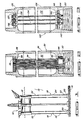
- FIG. 1 shows an offshore tension leg platform 10.
- the TLP 10 generally comprises a platform 12 floating on a body of water 14 and which is anchored to the bottom 16 of the body of water by a plurality of tensioned mooring elements 18 which extend between the floating platform 12 and anchoring means 20 which are located on the bottom 16 of the body of water 14.
- the anchoring means 20 are adapted for connection of a plurality of tensioned mooring elements 18 and are secured in position by a plurality of pilings extending into the bottom 16.
- the tensioned mooring elements 18 comprise a plurality of lightweight hybrid composite tubular assemblies 22 which are interconnected at their ends by a plurality of metallic connectors 24.
- the tensioned mooring elements 18 are maintained in constant tension between the anchoring means 20 and the floating platform 12 by the buoyancy of the floating platform 12 which is constantly maintained in excess of its operating weight under all conditions.
- the hybrid composite tubular assemblies 22 of the mooring elements 18 comprise a metallic outer tubular member 26 ( Figure 2) having connector portions welded thereto such as pin 28 and box 30 elements which are threaded for interconnection with other composite tubular assemblies 22.
- a high modulus composite tubular member 34 Disposed within the interior 32 of the metallic outer tubular member 26 is a high modulus composite tubular member 34.
- the high modulus composite tubular 34 is constructed of a high modulus, generally longitudinally oriented fibrous materials in a resin matrix.
- the composite tubular 34 comprises high modulus carbon fibers disposed in an epoxy matrix, the carbon fiber being disposed either longitudinally or in a low-pitch helical wind.
- carbon fibers are preferred, other fibrous materials may be used which either alone or in combination with carbon fibers meet the high modulus of elasticity requirements such as boron fibers, aramid fibers, and the like.
- the composite tubular 34 includes a radially- enlarged end portion 36, which has shown in Figure 2, is in compressive engagement against a radially extending land portion 38 of the pin element 28.
- the opposite end 40 of the composite tubular 34 comprises a threaded fitting 42 and a threaded nut 44 which is in compressive engagement with a radially extending land portion 46 of the box element 30.
- the threaded fitting 42 of the composite tubular 34 is preferably made of metal and the fibrous composite materials of the composite tubular 34 are bonded to the fitting 42 by means which are known in the art.
- a lightweight composite tubular assembly 122 comprises a metallic outer tubular member 126 which has a pin element 128 and box element 130 welded thereto.
- a high modulus composite tubular such as that indicated by 34 in Figure 2
- a plurality of high modulus composite tendons 134 are provided.
- the tendons 134 are constructed in a manner similar to the high modulus composite tubular 34, that is utilizing high modulus fibrous materials in a resin matrix.
- the tendons 134 may comprise parallel lay cable or composite rod of the high modulus fiber.
- a plurality of tendons 134 may be provided depending on the design requirements of the composite tubular assembly 122 in use.
- each of tendons 134 has an enlarged diameter dead end portion 136 which bears in compressive engagement against a perforated circular plate 137 which in turn bears against a radially inwardly extending land portion 138 of the pin element 128.
- the opposite end 140 of each of the tendons 134 includes a threaded end fitting 142 and a nut 144 which bears in compressive engagement against a second perforated circular plate member 145 which further bears in compressive engagement against a radially inwardly extending the land portion 146 of the box element 130.
- the tendons 134 may be comprised of a single length of high modulus composite cable.
- the plate elements 137,145 include a curved bearing block or pulley over which the single continuous cable is returned to the opposite end of the composite assembly 122.
- a sinuous winding of a single length of cable provides the same effect as the plurality of individual tendons 134 as shown in Figure 3. All of the tendons are prestressed by the tightening of a single nut on a threaded end fitting in the manner of the tightening of the nuts 144 on the end fittings 142 ( Figure 3).
- the illustrated arrangements enable use of low cost, welded-on mechanical connectors for simple.assembly of a tensioned mooring element.
- the weld is located in a position which is prestressed in compression and, therefore, is subjected to tensile loads during its service life.
- the tensile pretension, particularly for parallel lay cables, will lead to higher elastic modulus, which is desirable.
- the interior space 32,132 can be filled with a lightweightfoam to aid in internal stiffening.
- the axial stiffness of a hybrid composite tubular in accordance with the invention is proportional to the sum of the EA of the metal tubular and the EA of the composite rods wherein E is the elastic modulus of the component material and A is the cross sectional area of the component.
- the environmental load is distributed in proportion to the respective EA values.
- an all steel mooring system requires tubulars with a cross sectional area of 871 square centimetres (135 square inches) (63.5 centimetre (25") O.D.x4.45 centimetre (1-3/4") thickness).
- the weight in water of a mooring element of this design is 372 kilograms per metre (250 pounds per foot).
- the steel tubular thus contributes 17.5 percent of the required EA values.
- the remaining 82.5 percent total EA is provided by a high modulus composite tube or tendon system disposed within the tubular as shown in the drawings wherein the elastic modulus of the composite is 4.2 X 10 6 kilograms per square centimetre (60x10 6 psi) and the cross sectional area of the composite member is 355 square centimetres (55 square inches) giving an EA for the composite of 1.5x10 9 kilograms (3.3 X 10 9 pounds).
- the weight of the total hybrid composite mooring system of this example of the present invention in water is 77 kilograms per metre (52 pounds per foot).
- the total weight savings for the installation would be 4,300 tonnes. This weight saving can result in a cost saving that exceeds 32 million dollars in a TLP installation in addition to other benefits such as ease at handling, storage, joining and the like for the mooring system due to its smaller size and weight.
- the steel tubular is prestressed in compression by 1.7 kilograms per square centimetre (11 ksi), i.e.:
Landscapes
- Chemical & Material Sciences (AREA)
- Engineering & Computer Science (AREA)
- Combustion & Propulsion (AREA)
- Mechanical Engineering (AREA)
- Ocean & Marine Engineering (AREA)
- Earth Drilling (AREA)
- Lock And Its Accessories (AREA)
- Gears, Cams (AREA)
- Macromonomer-Based Addition Polymer (AREA)
Applications Claiming Priority (2)
| Application Number | Priority Date | Filing Date | Title |
|---|---|---|---|
| US684779 | 1984-12-21 | ||
| US06/684,779 US4990030A (en) | 1984-12-21 | 1984-12-21 | Hybrid composite mooring element for deep water offshore structures |
Publications (2)
| Publication Number | Publication Date |
|---|---|
| EP0191992A1 EP0191992A1 (en) | 1986-08-27 |
| EP0191992B1 true EP0191992B1 (en) | 1989-04-05 |
Family
ID=24749537
Family Applications (1)
| Application Number | Title | Priority Date | Filing Date |
|---|---|---|---|
| EP85309360A Expired EP0191992B1 (en) | 1984-12-21 | 1985-12-20 | Hybrid composite mooring element for deep water offshore structures |
Country Status (6)
| Country | Link |
|---|---|
| US (1) | US4990030A (da) |
| EP (1) | EP0191992B1 (da) |
| JP (1) | JPS61150892A (da) |
| CA (1) | CA1272640A (da) |
| DK (1) | DK588985A (da) |
| NO (1) | NO164402C (da) |
Families Citing this family (12)
| Publication number | Priority date | Publication date | Assignee | Title |
|---|---|---|---|---|
| US5197825A (en) * | 1986-11-12 | 1993-03-30 | Gotaverken Arendal Ab | Tendon for anchoring a semisubmersible platform |
| SE462906B (sv) * | 1986-11-12 | 1990-09-17 | Goetaverken Arendal Ab | Anordning vid foerankring av en semisubmersibel plattform |
| FR2613815B1 (fr) * | 1987-04-10 | 1989-06-23 | Bouygues Offshore | Tube en acier precontraint, notamment pour la realisation de lignes d'ancrage de plates-formes de production du type a lignes tendues, procede de manutention et de mise en place d'un tel tube, et plate-forme comprenant un tel tube |
| US5150987A (en) * | 1991-05-02 | 1992-09-29 | Conoco Inc. | Method for installing riser/tendon for heave-restrained platform |
| US6036404A (en) * | 1993-08-31 | 2000-03-14 | Petroleo Brasileiro S.A.-Petrobras | Foundation system for tension leg platforms |
| BR9303646A (pt) | 1993-08-31 | 1995-04-25 | Petroleo Brasileiro Sa | Sistema de fundação para plataformas de pernas atirantadas |
| WO2002095101A1 (en) * | 2001-04-27 | 2002-11-28 | Conoco Inc | Composite tether and methods for manufacturing, transporting, and installing same |
| WO2002087960A2 (en) | 2001-04-27 | 2002-11-07 | Conoco Inc | A floating platform having a spoolable tether installed thereon and method for tethering the platform using same |
| US20040105725A1 (en) * | 2002-08-05 | 2004-06-03 | Leverette Steven J. | Ultra-deepwater tendon systems |
| US20050067037A1 (en) * | 2003-09-30 | 2005-03-31 | Conocophillips Company | Collapse resistant composite riser |
| US20050100414A1 (en) * | 2003-11-07 | 2005-05-12 | Conocophillips Company | Composite riser with integrity monitoring apparatus and method |
| RU2526568C2 (ru) * | 2012-05-05 | 2014-08-27 | Общество с ограниченной ответственностью "Троицкий Крановый Завод" | Устройство для соединения якоря со швартовой балкой |
Family Cites Families (14)
| Publication number | Priority date | Publication date | Assignee | Title |
|---|---|---|---|---|
| US3517517A (en) * | 1968-09-19 | 1970-06-30 | Pan American Petroleum Corp | Encapsulated cable for marine use |
| US3709182A (en) * | 1970-02-24 | 1973-01-09 | Deep Oil Technology Inc | Anchor means and method of installing the same |
| US3882650A (en) * | 1974-05-21 | 1975-05-13 | Paul F Gugliotta | Pipe-and-ball truss array |
| US4275537A (en) * | 1977-05-26 | 1981-06-30 | Tension Structures, Inc. | Tension members |
| US4226555A (en) * | 1978-12-08 | 1980-10-07 | Conoco, Inc. | Mooring system for tension leg platform |
| US4285615A (en) * | 1978-12-13 | 1981-08-25 | Conoco, Inc. | Corrosion resistant tension leg cables |
| US4234270A (en) * | 1979-01-02 | 1980-11-18 | A/S Hoyer-Ellefsen | Marine structure |
| US4468157A (en) * | 1980-05-02 | 1984-08-28 | Global Marine, Inc. | Tension-leg off shore platform |
| FR2484355A1 (fr) * | 1980-06-12 | 1981-12-18 | Precontrainte Structures Ste F | Hauban sous-marin |
| GB2085939B (en) * | 1980-09-01 | 1985-03-06 | Mcalpine & Sons Ltd Sir Robert | Marine mooring cables |
| US4425056A (en) * | 1981-08-17 | 1984-01-10 | Conoco Inc. | Tension control system for controlling the tension in platform supporting tension legs. |
| CA1213838A (en) * | 1982-04-27 | 1986-11-12 | Frederick J. Policelli | Filament wound interlaminate tubular attachment and method of manufacture |
| US4516882A (en) * | 1982-06-11 | 1985-05-14 | Fluor Subsea Services, Inc. | Method and apparatus for conversion of semi-submersible platform to tension leg platform for conducting offshore well operations |
| FR2535281A1 (fr) * | 1982-10-29 | 1984-05-04 | Precontrainte Ste Fse | Hauban sous-marin a tirants en beton, notamment pour haubanage oblique |
-
1984
- 1984-12-21 US US06/684,779 patent/US4990030A/en not_active Expired - Fee Related
-
1985
- 1985-11-29 CA CA000496602A patent/CA1272640A/en not_active Expired - Lifetime
- 1985-12-09 JP JP60275231A patent/JPS61150892A/ja active Pending
- 1985-12-18 NO NO855130A patent/NO164402C/no unknown
- 1985-12-18 DK DK588985A patent/DK588985A/da not_active Application Discontinuation
- 1985-12-20 EP EP85309360A patent/EP0191992B1/en not_active Expired
Also Published As
| Publication number | Publication date |
|---|---|
| NO855130L (no) | 1986-06-23 |
| DK588985A (da) | 1986-06-22 |
| NO164402C (no) | 1990-10-03 |
| CA1272640A (en) | 1990-08-14 |
| US4990030A (en) | 1991-02-05 |
| NO164402B (no) | 1990-06-25 |
| EP0191992A1 (en) | 1986-08-27 |
| JPS61150892A (ja) | 1986-07-09 |
| DK588985D0 (da) | 1985-12-18 |
Similar Documents
| Publication | Publication Date | Title |
|---|---|---|
| US4768455A (en) | Dual wall steel and fiber composite mooring element for deep water offshore structures | |
| EP0191992B1 (en) | Hybrid composite mooring element for deep water offshore structures | |
| CA1147214A (en) | Interconnecting system for marine floats | |
| WO1996014473A1 (en) | Deep water offshore apparatus | |
| US8764346B1 (en) | Tension-based tension leg platform | |
| US10507894B2 (en) | Self-restoring motion compensating mooring system | |
| US4696603A (en) | Compliant offshore platform | |
| JPS63279993A (ja) | 単脚引張り脚式プラットホーム | |
| WO2010135725A1 (en) | Battered column offshore platform | |
| KR100382894B1 (ko) | 반잠수되며이동가능한조립식해상플랫폼지지물 | |
| CA1307171C (en) | Mooring apparatus and method of installation for deep water tension leg platform | |
| US3903705A (en) | Apparatus for anchoring marine structures | |
| EP0072692B1 (en) | Controlling the tension in platform supporting tension legs | |
| EP0311398A1 (en) | Mooring apparatus for deep water tension leg platform | |
| EP0830280B1 (en) | Hollow concrete-walled structure for marine use | |
| Mangiavacchi et al. | Design Criteria Of Apile Founded Guyed Tower. | |
| EP0045651A2 (en) | Apparatus and method for supporting a tubular riser | |
| US6478511B1 (en) | Floating system with tensioned lines | |
| EP0189671B1 (en) | Dual wall composite mooring element for deep water offshore structures | |
| USH1246H (en) | Buoyant cable tether | |
| US20150037103A1 (en) | Cellular tendons for tlp | |
| US5884576A (en) | Mooring arrangement | |
| US7422394B2 (en) | Tendon for tension leg platform | |
| US6851894B1 (en) | Deep water TLP tether system | |
| US20040105725A1 (en) | Ultra-deepwater tendon systems |
Legal Events
| Date | Code | Title | Description |
|---|---|---|---|
| PUAI | Public reference made under article 153(3) epc to a published international application that has entered the european phase |
Free format text: ORIGINAL CODE: 0009012 |
|
| AK | Designated contracting states |
Kind code of ref document: A1 Designated state(s): FR GB NL |
|
| 17P | Request for examination filed |
Effective date: 19870105 |
|
| 17Q | First examination report despatched |
Effective date: 19870828 |
|
| GRAA | (expected) grant |
Free format text: ORIGINAL CODE: 0009210 |
|
| AK | Designated contracting states |
Kind code of ref document: B1 Designated state(s): FR GB NL |
|
| ET | Fr: translation filed | ||
| PLBE | No opposition filed within time limit |
Free format text: ORIGINAL CODE: 0009261 |
|
| STAA | Information on the status of an ep patent application or granted ep patent |
Free format text: STATUS: NO OPPOSITION FILED WITHIN TIME LIMIT |
|
| 26N | No opposition filed | ||
| PGFP | Annual fee paid to national office [announced via postgrant information from national office to epo] |
Ref country code: FR Payment date: 19911212 Year of fee payment: 7 |
|
| PGFP | Annual fee paid to national office [announced via postgrant information from national office to epo] |
Ref country code: NL Payment date: 19911231 Year of fee payment: 7 |
|
| PG25 | Lapsed in a contracting state [announced via postgrant information from national office to epo] |
Ref country code: NL Effective date: 19930701 |
|
| NLV4 | Nl: lapsed or anulled due to non-payment of the annual fee | ||
| PG25 | Lapsed in a contracting state [announced via postgrant information from national office to epo] |
Ref country code: FR Effective date: 19930831 |
|
| REG | Reference to a national code |
Ref country code: FR Ref legal event code: ST |
|
| PGFP | Annual fee paid to national office [announced via postgrant information from national office to epo] |
Ref country code: GB Payment date: 19961108 Year of fee payment: 12 |
|
| PG25 | Lapsed in a contracting state [announced via postgrant information from national office to epo] |
Ref country code: GB Free format text: LAPSE BECAUSE OF NON-PAYMENT OF DUE FEES Effective date: 19971220 |
|
| GBPC | Gb: european patent ceased through non-payment of renewal fee |
Effective date: 19971220 |