EP0191851B1 - Unterdruckflasche für die redon-wunddrainage - Google Patents
Unterdruckflasche für die redon-wunddrainage Download PDFInfo
- Publication number
- EP0191851B1 EP0191851B1 EP85904442A EP85904442A EP0191851B1 EP 0191851 B1 EP0191851 B1 EP 0191851B1 EP 85904442 A EP85904442 A EP 85904442A EP 85904442 A EP85904442 A EP 85904442A EP 0191851 B1 EP0191851 B1 EP 0191851B1
- Authority
- EP
- European Patent Office
- Prior art keywords
- bottle
- chambers
- piece
- wound
- redon
- Prior art date
- Legal status (The legal status is an assumption and is not a legal conclusion. Google has not performed a legal analysis and makes no representation as to the accuracy of the status listed.)
- Expired
Links
- 206010052428 Wound Diseases 0.000 description 21
- 208000027418 Wounds and injury Diseases 0.000 description 21
- 238000000034 method Methods 0.000 description 3
- 206010048629 Wound secretion Diseases 0.000 description 2
- 230000036512 infertility Effects 0.000 description 2
- 238000005192 partition Methods 0.000 description 2
- 238000004026 adhesive bonding Methods 0.000 description 1
- 239000003570 air Substances 0.000 description 1
- 239000012080 ambient air Substances 0.000 description 1
- 230000001580 bacterial effect Effects 0.000 description 1
- 244000052616 bacterial pathogen Species 0.000 description 1
- 230000000721 bacterilogical effect Effects 0.000 description 1
- 238000007664 blowing Methods 0.000 description 1
- 230000006835 compression Effects 0.000 description 1
- 238000007906 compression Methods 0.000 description 1
- 238000011109 contamination Methods 0.000 description 1
- 238000002683 hand surgery Methods 0.000 description 1
- 208000015181 infectious disease Diseases 0.000 description 1
- 230000002458 infectious effect Effects 0.000 description 1
- 239000012528 membrane Substances 0.000 description 1
- 230000000474 nursing effect Effects 0.000 description 1
- 230000002980 postoperative effect Effects 0.000 description 1
- 238000007789 sealing Methods 0.000 description 1
- 230000028327 secretion Effects 0.000 description 1
- 238000003466 welding Methods 0.000 description 1
- 230000029663 wound healing Effects 0.000 description 1
Images

Classifications
-
- A—HUMAN NECESSITIES
- A61—MEDICAL OR VETERINARY SCIENCE; HYGIENE
- A61M—DEVICES FOR INTRODUCING MEDIA INTO, OR ONTO, THE BODY; DEVICES FOR TRANSDUCING BODY MEDIA OR FOR TAKING MEDIA FROM THE BODY; DEVICES FOR PRODUCING OR ENDING SLEEP OR STUPOR
- A61M1/00—Suction or pumping devices for medical purposes; Devices for carrying-off, for treatment of, or for carrying-over, body-liquids; Drainage systems
- A61M1/64—Containers with integrated suction means
- A61M1/66—Pre-evacuated rigid containers, e.g. Redon bottles
-
- A—HUMAN NECESSITIES
- A61—MEDICAL OR VETERINARY SCIENCE; HYGIENE
- A61M—DEVICES FOR INTRODUCING MEDIA INTO, OR ONTO, THE BODY; DEVICES FOR TRANSDUCING BODY MEDIA OR FOR TAKING MEDIA FROM THE BODY; DEVICES FOR PRODUCING OR ENDING SLEEP OR STUPOR
- A61M1/00—Suction or pumping devices for medical purposes; Devices for carrying-off, for treatment of, or for carrying-over, body-liquids; Drainage systems
- A61M1/71—Suction drainage systems
- A61M1/73—Suction drainage systems comprising sensors or indicators for physical values
- A61M1/732—Visual indicating means for vacuum pressure
Definitions
- the invention relates to a vacuum bottle for Redon wound drainage.
- DE-AS-2639715 describes a one-piece plastic bottle for single use with a pressure indicator and a connecting piece for a hose leading to a wound drain. These bottles are pressurized to more than 90 kPa under sterile conditions. When applying to a wound drain, there is therefore a corresponding pressure difference between the wound cavity in which the drain is located and the surroundings. As a result of this pressure difference, the wound surfaces are pressed against one another, which leads to the wound gap being immobilized. The tissue bridging of the wound gap is thus facilitated, d. H. promote wound healing.
- the object of the present invention was to provide a vacuum bottle for Redon wound drainage, with which the dangers associated with changing the bottle can be avoided.
- the vacuum bottle comprises two separate chambers which are connected to one another and to a connecting hose by means of a T-piece, it being possible for all accesses to the T-piece to be disconnected.
- the two chambers of the vacuum bottles according to the invention either have an essentially identical internal volume or are distinguished by different internal volumes.
- a preferred object are vacuum bottles, the two chambers of which are each equipped with a pressure indicator.
- both chambers of the vacuum bottle according to the invention are evacuated and all the connecting pieces of the T-piece are clamped off by means of clamps.
- the free connector of the T-piece is connected to the connecting hose leading to the wound drain.
- the clamp on the originally free connector of the T-piece and the clamp between the T-piece and the first chamber of the vacuum bottle are opened.
- the clamp between the T-piece and the first chamber is closed and the clamp between the T-piece and the second chamber is opened. Further wound secretions now flow into the second chamber. This «switching from the first to the second chamber avoids the risks associated with changing the bottle.
- the closing of the clamp between the T-piece and the first chamber can be omitted instead of the described "switching over, and a pressure equalization between the two chambers can be brought about by opening the clamp between the T-piece and the second chamber. In this case, the remaining volume of the first chamber is also available for further drainage.
- Another variant in the use of the double-chamber suction bottle according to the invention is to reduce the negative pressure in the first chamber to a desired value before establishing a conductive connection between the first chamber and wound drain, ie before opening the clamp between the T-piece and the first chamber .
- This can e.g. B. happen by piercing a bellows used as a pressure indicator or another rubber part acting as a self-sealing membrane by means of a thin puncture cannula.
- the cannula is provided with a bacterial filter at its rear end.
- the wound drainage can be started with a reduced vacuum and later by «switching to the second chamber or « switching on »the second chamber continue with increased negative pressure.
- This procedure is regarded as advantageous in certain surgical operations and can take place with the double-chamber bottle according to the invention without changing the bottle.
- the vacuum bottle according to the invention is produced by methods known per se.
- the bottle is made from two half bottles, e.g. B. joined by gluing or welding.
- the half-bottles can be manufactured in the usual way by blowing.
- the volume of the vacuum bottle can be varied within wide limits depending on the intended use. For example, to drain small wounds, such as z. B. arise in hand surgery operations, a vacuum bottle with a total volume of 100 to 200 cm 3 are provided. For larger operations, the vacuum bottles can have a total volume of, for example, 800 to 1,000 cm 3 . Vacuum bottles with a total volume of 400 to 600 c m3 are preferred .
- Vacuum bottles can be produced for special purposes, in which the two chambers have different volumes.
- the vacuum bottle consists of two separate bottles with a pressure indicator and connecting piece for a hose line, which are firmly connected to one another by a common holder and whose interiors are connected to one another and to a connecting line via a T-piece.
- Possible pressure indicators are, for example, those which are customary in the commercially available vacuum bottles for Redon wound drainage. Further possible embodiments for pressure indicators for Redon bottles are e.g. B. described in EP-A2-0 061 723 and EP-A2-0 036 546.
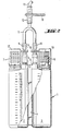
- the vacuum bottle 1 in Fig. 1 is partially broken open.
- a partition 4 separates the interior of the vacuum bottle 1 into a first chamber 2 and a second chamber 3.
- the vacuum bottle 1 has a connecting piece 5, 6 and a pressure indicator 7, 8 for each of the chambers 2, 3.
- the pressure indicators 7, 8 are in the Embodiment of FIG. 1 shown as bellows.
- Hose connectors 9, 10 are attached to the connecting pieces 5, 6 and establish the connection with the T-piece 11.
- a hose connection piece 12 is plugged onto the remaining outlet of the T-piece 11 and establishes the connection to the connection hose 13 leading to the wound drain (not shown).
- Sliding clamps 14, 15, 16 are attached to the hose connectors 9, 10, 12.
- FIG. 2 shows a further embodiment of a vacuum bottle 1 in a partially broken-open representation.
- the partition 4 is designed here as a connecting web between the two chambers 2 and 3, which are essentially cylindrical in cross section. Scales are plotted on the outside of the chambers 2 and 3, by means of which the respective degree of filling of the chambers can be read.
- the pressure indicators 7 and 8 are designed as bellows, which are surrounded by sleeves 17 and 18, on which scales for displaying the pressure in the chambers 2 and 3 can be applied.
- the remaining elements provided with reference numerals correspond to those in FIG. 1.
Landscapes
- Health & Medical Sciences (AREA)
- Heart & Thoracic Surgery (AREA)
- Vascular Medicine (AREA)
- Engineering & Computer Science (AREA)
- Anesthesiology (AREA)
- Biomedical Technology (AREA)
- Hematology (AREA)
- Life Sciences & Earth Sciences (AREA)
- Animal Behavior & Ethology (AREA)
- General Health & Medical Sciences (AREA)
- Public Health (AREA)
- Veterinary Medicine (AREA)
- External Artificial Organs (AREA)
- Media Introduction/Drainage Providing Device (AREA)
Description
- Die Erfindung bezieht sich auf eine Unterdruckflasche für die Redon-Wunddrainage.
- Die postoperative Wunddrainage mittels hohem Unterdruck (Redon-Technik) hat eine sehr weite Verbreitung gefunden. In der DE-AS-2639715 wird eine einstückige Flasche aus Kunststoff zum einmaligen Gebrauch mit einem Druckanzeiger und einem Anschlußstutzen für einen zu einem Wunddrain führenden Schlauch beschrieben. Diese Flaschen werden unter sterilen Bedingungen mit einem Unterdruck von mehr als 90 kPa versehen. Beim Anlegen an einen Wunddrain kommt es daher zwischen der Wundhöhle, in der der Drain liegt, und der Umgebung zu einer entsprechenden Druckdifferenz. Durch diese Druckdifferenz werden die Wundflächen aneinander gepreßt, was zu einer Ruhigstellung des Wundspaltes führt. Die gewebliche Oberbrückung des Wundspaltes wird somit erleichtert, d. h. die Heilung der Wunde gefördert.
- Bei der Wunddrainage nach Redon liegt ein geschlossenes System vor. Eine Kontamination über das Drainagesystem ist daher weitgehend ausgeschlossen. Kritisch ist jedoch eine Öffnung des Systems, was z. B. beim Wechseln der Saugflasche erforderlich ist. Besonders gefährlich ist ein Flaschenwechsel, bei dem versehentlich die Saugleitung vorher nicht dicht verschlossen wurde. In diesem Fall wird Sekret und keimbeladene Umgebungsluft in die Wunde gesaugt. Zudem wird die Druckdifferenz zwischen Umgebung und dem Inneren der Wunde ausgeglichen, was zu einer unerwünschten Aufhebung des Zusammenpressens der Wundränder führt. Bakteriologische Untersuchungen (A. Härle, Hygiene + Medizin 7[1982]427) ergeben, daß insbesondere der Flaschenwechsel die Sterilitätssituation des Wunddrainage-Systems negativ beeinflußt. Der Flaschenwechsel ist auch für das Pflegepersonal nicht unbedenklich, da die Gefahr der Berührung mit eventuell infektiösem Wundsekret besteht.
- In manchen Anwendungsfällen ist es zweckmäßig, zu Beginn der Wunddrainage mit einem geringeren Unterdruck zu arbeiten. Dies kann bewerkstelligt werden, indem zuerst eine teilweise belüftete Unterdruckflasche eingesetzt wird, die dann später gegen eine Unterdruckflasche mit vollem Vakuum ausgetauscht wird. Auch hier kann es beim Flaschenwechsel zu Sterilitätsproblemen kommen.
- Aufgabe der vorliegenden Erfindung war es, eine Unterdruckflasche für die Redon-Wunddrainage zur Verfügung zu stellen, mit der die mit dem Flaschenwechsel verbundenen Gefahren vermieden werden können.
- Erfindungsgemäß gelöst wird diese Aufgabe dadurch, daß die Unterdruckflasche zwei voneinander getrennte Kammern umfaßt, die über ein T-Stück miteinander und mit einem Verbindungsschlauch in Verbindung stehen, wobei alle Zugänge des T-Stücks abklemmbar sind. Die beiden Kammern der erfindungsgegenständlichen Unterdruckflaschen weisen entweder ein im wesentlichen identisches Innenvolumen auf oder zeichnen sich durch unterschiedliche Innenvolumina aus.
- Ein bevorzugter Gegenstand sind Unterdruckflaschen, deren beide Kammern jeweils mit einem Druckanzeiger ausgestattet sind.
- Im Anlieferungszustand sind beide Kammern der erfindungsgemäßen Unterdruckflasche evakuiert und alle Anschlußstücke des T-Stücks mittels Klemmen abgeklemmt. Bei der Anwendung wird das freie Anschlußstück des T-Stücks mit dem zum Wunddrain führenden Verbindungsschlauch verbunden. Sodann werden die Klemme am ursprünglich freien Anschlußstück des T-Stücks und die Klemme zwischen T-Stück und der ersten Kammer der Unterdruckflasche geöffnet. Sobald bei herkömmlichen Einkammersaugflaschen ein Flaschenwechsel vorgenommen werden würde, wird die Klemme zwischen T-Stück und der ersten Kammer geschlossen und die Klemme zwischen T-Stück und der zweiten Kammer geöffnet. Weiteres Wundsekret fließt nun in die zweite Kammer. Dieses « Umschalten von der ersten auf die zweite Kammer vermeidet die mit dem Flaschenwechsel verbundenen Risiken.
- Gewünschtenfalls kann statt des beschriebenen « Umschaltens das Schließen der Klemme zwischen T-Stück und erster Kammer unterlassen werden und durch Öffnen der Klemme zwischen T-Stück und zweiter Kammer ein Druckausgleich zwischen den beiden Kammern herbeigeführt werden. In diesem Fall steht für die weitere Drainage auch noch das restliche Volumen der ersten Kammer zur Verfügung.
- Eine weitere Variante in der Anwendung der erfindungsgemäßen Doppelkammersaugflasche besteht darin, vor dem Herstellen einer leitenden Verbindung zwischen erster Kammer und Wunddrain, d. h. vor dem Öffnen der Klemme zwischen T-Stück und erster Kammer, den Unterdruck in der ersten Kammer auf einen gewünschten Wert zu reduzieren. Dies kann z. B. durch Anstechen eines als Druckanzeiger verwendeten Faltenbalgs oder eines anderen als selbstabdichtende Membran wirkenden Gummiteils mittels einer dünnen Punktionskanüle geschehen. Zur Vermeidung des Einschleppens von Keimen aus der Umluft ist die Kanüle an ihrem rückwärtigen Ende mit einem Bakterienfilter versehen. Durch diese Reduzierung des Drucks kann die Wunddrainage mit einem verringerten Unterdruck begonnen werden und später durch « Umschalten auf die zweite Kammer oder « Zuschalten » der zweiten Kammer bei erhöhtem Unterdruck fortgesetzt werden. Diese Vorgangsweise wird bei bestimmten chirurgischen Operationen als vorteilhaft angesehen und kann mit der erfindungsgemäßen Doppelkammerflasche ohne Flaschenwechsel stattfinden.
- Die erfindungsgemäße Unterdruckflasche wird durch an sich bekannte Verfahren hergestellt. Beispielsweise wird die Flasche aus zwei Halbflaschen z. B. durch Kleben oder Verschweißen zusammengefügt. Die Halbflaschen können auf übliche Weise im Blasverfahren hergestellt werden.
- Das Volumen der Unterdruckflasche kann in weiten Grenzen je nach Verwendungszweck variiert werden. Zum Beispiel kann zur Drainage kleiner Wunden, wie sie z. B. bei handchirurgischen Operationen entstehen, eine Unterdruckflasche mit einem Gesamtvolumen von 100 bis 200 cm3 bereitgestellt werden. Für größere Operationen können die Unterdruckflaschen ein Gesamtvolumen von beispielsweise 800 bis 1 000 cm3 aufweisen. Bevorzugt sind Unterdruckflaschen mit einem Gesamtvolumen von 400 bis 600 cm3.
- Für besondere Zwecke können Unterdruckflaschen hergestellt werden, bei denen die beiden Kammern unterschiedliche Volumina besitzen.
- Eine Ausgestaltung der Erfindung besteht darin, daß die Unterdruckflasche aus zwei getrennten Flaschen mit Druckanzeiger und Anschlußstutzen für eine Schlauchleitung besteht, die durch eine gemeinsame Halterung fest miteinander verbunden sind und deren Innenräume über ein T-Stück miteinander und mit einer Verbindungsleitung in Verbindung stehen.
- Als Druckanzeiger kommen beispielsweise solche in Frage, wie sie bei den handelsüblichen Unterdruckflaschen für die Redon-Wunddrainage üblich sind. Weitere in Frage kommende Ausführungsformen für Druckanzeiger für Redon-Flaschen sind z. B. in der EP-A2-0 061 723 und der EP-A2-0 036 546 beschrieben.
- Nachstehend wird die Erfindung anhand von zwei Ausführungsbeispielen näher erläutert.
- Fig. 1 zeigt in teilsweise schematisierter Darstellung eine Unterdruckflasche.
- Fig. 2 zeigt eine weitere Ausführungsform.
- Die Unterdruckflasche 1 in Fig. 1 ist teilweise aufgebrochen gezeichnet. Eine Trennwand 4 trennt den Innenraum der Unterdruckflasche 1 in eine erste Kammer 2 und eine zweite Kammer 3. Die Unterdruckflasche 1 besitzt für jede der Kammern 2, 3 einen Anschlußstutzen 5, 6 und einen Druckanzeiger 7, 8. Die Druckanzeiger 7, 8 sind im Ausführungsbeispiel der Fig. 1 als Faltenbälge dargestellt. Auf die Anschlußstutzen 5, 6 sind Schlauchverbindungsstücke 9, 10 aufgezogen, die die Verbindung mit dem T-Stück 11 herstellen. Auf dem verbleibenden Ausgang des T-Stücks 11 ist ein Schlauchverbindungsstück 12 aufgesteckt, das die Verbindung zu dem zum Wunddrain (nicht dargestellt) führenden Verbindungsschlauch 13 herstellt. Auf den Schlauchverbindungsstücken 9, 10, 12 sind Schiebeklemmen 14, 15, 16 aufgesteckt.
- Fig. 2 zeigt eine weitere Ausführungsform einer Unterdruckflasche 1 in teilweise aufgebrochener Darstellung. Die Trennwand 4 ist hier als Verbindungssteg zwischen den beiden im Querschnitt im wesentlichen zylinderförmig ausgebildeten Kammern 2 und 3 gestaltet. Auf den Außenseiten der Kammern 2 und 3 sind Skalen aufgetragen anhand derer der jeweilige Füllungsgrad der Kammern abzulesen ist. Die Druckanzeiger 7 und 8 sind wie bei der Ausführungsform nach der Fig. 1 als Faltenbälge ausgestaltet, die von Hülsen 17 und 18 umgeben sind, auf denen Skalen für die Anzeige des Druckes in den Kammern 2 und 3 aufgebracht sein können. Die übrigen mit Bezugszeichen versehenen Elemente entsprechen denen in Fig. 1.
Claims (6)
Priority Applications (1)
| Application Number | Priority Date | Filing Date | Title |
|---|---|---|---|
| AT85904442T ATE42471T1 (de) | 1984-08-29 | 1985-08-20 | Unterdruckflasche fuer die redon-wunddrainage. |
Applications Claiming Priority (2)
| Application Number | Priority Date | Filing Date | Title |
|---|---|---|---|
| CH413884 | 1984-08-29 | ||
| CH4138/84 | 1984-08-29 |
Publications (2)
| Publication Number | Publication Date |
|---|---|
| EP0191851A1 EP0191851A1 (de) | 1986-08-27 |
| EP0191851B1 true EP0191851B1 (de) | 1989-04-26 |
Family
ID=4270523
Family Applications (1)
| Application Number | Title | Priority Date | Filing Date |
|---|---|---|---|
| EP85904442A Expired EP0191851B1 (de) | 1984-08-29 | 1985-08-20 | Unterdruckflasche für die redon-wunddrainage |
Country Status (5)
| Country | Link |
|---|---|
| US (1) | US5078704A (de) |
| EP (1) | EP0191851B1 (de) |
| JP (1) | JPS62500081A (de) |
| DE (1) | DE3569674D1 (de) |
| WO (1) | WO1986001412A1 (de) |
Cited By (1)
| Publication number | Priority date | Publication date | Assignee | Title |
|---|---|---|---|---|
| US8202262B2 (en) | 1994-08-22 | 2012-06-19 | Kci Licensing, Inc. | Wound therapy device and related methods |
Families Citing this family (13)
| Publication number | Priority date | Publication date | Assignee | Title |
|---|---|---|---|---|
| US6077233A (en) * | 1998-03-12 | 2000-06-20 | Blake, Iii; Joseph W | Blood coagulation test system |
| US6325788B1 (en) | 1998-09-16 | 2001-12-04 | Mckay Douglas William | Treatment of wound or joint for relief of pain and promotion of healing |
| ATE432724T1 (de) | 1999-03-09 | 2009-06-15 | Covidien Ag | Medizinische drainagevorrichtung mit durchflusswiderstand |
| FR2861282B1 (fr) * | 2003-10-27 | 2007-07-06 | Patrice Richard | Dispositif de prelevement de sang placentaire. |
| GB2407508B (en) * | 2003-10-31 | 2005-09-28 | Angus Buchan Gordon | Closed sterile drainage device |
| US8539992B2 (en) * | 2011-04-27 | 2013-09-24 | Dsi Underground Systems, Inc. | Apparatus and method for anchor bolt grouting |
| DE102011114266A1 (de) | 2011-09-23 | 2013-03-28 | Michael Yim | Wundabsaugsystem |
| US10441251B2 (en) * | 2013-02-26 | 2019-10-15 | Pfm Medical, Inc. | Drainage system for wounds |
| WO2015086037A1 (en) | 2013-12-13 | 2015-06-18 | Vac Stent Medtec Ag | Suction stent, stent system, and method for sealing a leakage |
| DE202016100153U1 (de) * | 2016-01-14 | 2017-04-20 | Pfm Medical Ag | Behältnis zur Drainage von Flüssigkeiten beziehungsweise Wundsekret |
| KR102039558B1 (ko) * | 2016-10-17 | 2019-11-01 | 이현우 | 휴대형 의료용 진공 흡입기구 |
| WO2018074722A1 (ko) * | 2016-10-17 | 2018-04-26 | 이현우 | 휴대형 의료용 진공 흡입기구 |
| KR102718527B1 (ko) * | 2022-02-07 | 2024-10-16 | 인제대학교 산학협력단 | 흉수환자의 흉막 삼출액 배수를 위한 카테터 연결젠더 |
Family Cites Families (14)
| Publication number | Priority date | Publication date | Assignee | Title |
|---|---|---|---|---|
| US1099713A (en) * | 1913-07-01 | 1914-06-09 | Hilary J Morris | Beer-cock. |
| US3604410A (en) * | 1968-09-11 | 1971-09-14 | Gary L Whitacre | Multitube blood sampler |
| US3730170A (en) * | 1971-04-29 | 1973-05-01 | T Michael | Apparatus for distributing a sample of blood to a plurality of cultures |
| FR2155136A5 (de) * | 1971-10-08 | 1973-05-18 | Cinqualbre Paul | |
| US3843016A (en) * | 1972-08-04 | 1974-10-22 | Thermo Electron Corp | Disposable aspirator |
| US3929133A (en) * | 1974-11-20 | 1975-12-30 | Int Pregnancy Advisory Service | Apparatus for removing, washing and displaying fragmentary products of operative procedures |
| US4018224A (en) * | 1976-04-07 | 1977-04-19 | Deknatel, Inc. | Underwater drainage device with dual collection chambers |
| US4265118A (en) * | 1978-08-24 | 1981-05-05 | Intermedicat Gmbh | Urine collecting and measuring instrument |
| US4376439A (en) * | 1979-04-28 | 1983-03-15 | Lauterjung F G | Suction bottle for medical purposes particularly for the connection of drainage tubes |
| CA1168539A (en) * | 1979-06-04 | 1984-06-05 | Edward M. Goldberg | Apparatus and method for introducing fluid into and removing fluid from a living subject |
| DE2934915C2 (de) * | 1979-08-29 | 1986-12-04 | Volker O. Prof. Dr.Med. 8012 Ottobrunn Lang | Sekret-Auffangvorrichtung für den Einmalgebrauch |
| DE3011163C2 (de) * | 1980-03-22 | 1982-07-15 | Sterimed Gesellschaft für medizinischen Bedarf mbH, 6600 Saarbrücken | Saugflasche zum Absaugen von Sekreten aus Wundhöhlen |
| US4445884A (en) * | 1981-08-14 | 1984-05-01 | Bioresearch Inc. | Air purge unit for auto transfusion apparatus |
| DE3150500A1 (de) * | 1981-12-21 | 1983-06-30 | Friedrich Gerd 5000 Köln Lauterjung | Saugflasche fuer medizinische zwecke |
-
1985
- 1985-08-20 EP EP85904442A patent/EP0191851B1/de not_active Expired
- 1985-08-20 DE DE8585904442T patent/DE3569674D1/de not_active Expired
- 1985-08-20 JP JP60503984A patent/JPS62500081A/ja active Pending
- 1985-08-20 WO PCT/EP1985/000427 patent/WO1986001412A1/de not_active Ceased
-
1987
- 1987-10-16 US US07/110,544 patent/US5078704A/en not_active Expired - Fee Related
Cited By (1)
| Publication number | Priority date | Publication date | Assignee | Title |
|---|---|---|---|---|
| US8202262B2 (en) | 1994-08-22 | 2012-06-19 | Kci Licensing, Inc. | Wound therapy device and related methods |
Also Published As
| Publication number | Publication date |
|---|---|
| EP0191851A1 (de) | 1986-08-27 |
| WO1986001412A1 (fr) | 1986-03-13 |
| US5078704A (en) | 1992-01-07 |
| JPS62500081A (ja) | 1987-01-16 |
| DE3569674D1 (en) | 1989-06-01 |
Similar Documents
| Publication | Publication Date | Title |
|---|---|---|
| WO1986001412A1 (fr) | Flacon de sous-pression pour drainage redon de plaies | |
| US4429852A (en) | Adapter | |
| DE69309757T2 (de) | Chirurgische Kassette | |
| EP2146774A1 (de) | Drainageschlaucheinheit | |
| DE69332440T2 (de) | WECHSELLADESYSTEM FüR KASSETTEN FÜR EIN CHIRURGISCHES INSTRUMENT | |
| DE3852603T2 (de) | Autotransfusionsvorrichtung mit zwei Kammern. | |
| DE60037824T2 (de) | Wundabsaugungsvorrichtung mit mehrlumigem steckverbinder | |
| DE3532560C2 (de) | Verschlußvorrichtung für das Mundstück eines Endoskopes | |
| DE2950323C2 (de) | Sauginstrument für medizinische Zwecke | |
| DE2103187C3 (de) | Medizinische Wegwerfvorrichtung zum Absaugen von Flüssigkeiten | |
| EP0454178A1 (de) | Autotransfusionsgerät | |
| DE2628719A1 (de) | Verbindungsstueck zur entnahme von fluessigkeitsproben aus einer geschlossenen anordnung zur ableitung einer fluessigkeit | |
| CH700975A1 (de) | Drainageschlauchvorrichtung und kuppelungseinheit. | |
| DE2528776A1 (de) | Chirurgische absaugvorrichtung | |
| DE3321621A1 (de) | Vorrichtung zum punktieren von gewebe | |
| EP0252258A1 (de) | Injektionsstelle für medizinische Flüssigkeiten | |
| DE102015110432A1 (de) | Instillationsadapter für ein Unterdruckwundbehandlungssystem | |
| DE102012108248B3 (de) | Medizinischer Drainageschlauch | |
| DE3687457T2 (de) | Schnell ansprechende, schlauchlose aspirations-sammelkassette. | |
| DE202016100153U1 (de) | Behältnis zur Drainage von Flüssigkeiten beziehungsweise Wundsekret | |
| WO1984002078A1 (fr) | Dispositif pour aspirer et degager des liquides medicaux | |
| DE7818869U1 (de) | Drainageschlauch zum absaugen von wundsekret bei der postoperativen nachbehandlung in der chirurgie | |
| DE102011052735A1 (de) | Medizinischer Drainageschlauch | |
| WO2005087290A1 (de) | Vorrichtung zum wechseln und/oder andocken von funktionsmodulen | |
| DE1491755C3 (de) | Handabsauggerät für medizinische Zwecke |
Legal Events
| Date | Code | Title | Description |
|---|---|---|---|
| PUAI | Public reference made under article 153(3) epc to a published international application that has entered the european phase |
Free format text: ORIGINAL CODE: 0009012 |
|
| 17P | Request for examination filed |
Effective date: 19860425 |
|
| AK | Designated contracting states |
Kind code of ref document: A1 Designated state(s): AT BE CH DE FR GB IT LI LU NL SE |
|
| 17Q | First examination report despatched |
Effective date: 19871126 |
|
| RAP1 | Party data changed (applicant data changed or rights of an application transferred) |
Owner name: STERIMED GESELLSCHAFT FUER MEDIZINISCHEN BEDARF MB |
|
| GRAA | (expected) grant |
Free format text: ORIGINAL CODE: 0009210 |
|
| AK | Designated contracting states |
Kind code of ref document: B1 Designated state(s): AT BE CH DE FR GB IT LI LU NL SE |
|
| REF | Corresponds to: |
Ref document number: 42471 Country of ref document: AT Date of ref document: 19890515 Kind code of ref document: T |
|
| REF | Corresponds to: |
Ref document number: 3569674 Country of ref document: DE Date of ref document: 19890601 |
|
| ITF | It: translation for a ep patent filed | ||
| ET | Fr: translation filed | ||
| GBT | Gb: translation of ep patent filed (gb section 77(6)(a)/1977) | ||
| PLBE | No opposition filed within time limit |
Free format text: ORIGINAL CODE: 0009261 |
|
| STAA | Information on the status of an ep patent application or granted ep patent |
Free format text: STATUS: NO OPPOSITION FILED WITHIN TIME LIMIT |
|
| 26N | No opposition filed | ||
| ITTA | It: last paid annual fee | ||
| EPTA | Lu: last paid annual fee | ||
| EAL | Se: european patent in force in sweden |
Ref document number: 85904442.2 |
|
| PGFP | Annual fee paid to national office [announced via postgrant information from national office to epo] |
Ref country code: FR Payment date: 19980709 Year of fee payment: 14 |
|
| PGFP | Annual fee paid to national office [announced via postgrant information from national office to epo] |
Ref country code: AT Payment date: 19980714 Year of fee payment: 14 |
|
| PGFP | Annual fee paid to national office [announced via postgrant information from national office to epo] |
Ref country code: SE Payment date: 19980715 Year of fee payment: 14 |
|
| PGFP | Annual fee paid to national office [announced via postgrant information from national office to epo] |
Ref country code: GB Payment date: 19980721 Year of fee payment: 14 |
|
| PGFP | Annual fee paid to national office [announced via postgrant information from national office to epo] |
Ref country code: NL Payment date: 19980728 Year of fee payment: 14 |
|
| PGFP | Annual fee paid to national office [announced via postgrant information from national office to epo] |
Ref country code: CH Payment date: 19980804 Year of fee payment: 14 |
|
| PGFP | Annual fee paid to national office [announced via postgrant information from national office to epo] |
Ref country code: BE Payment date: 19980813 Year of fee payment: 14 |
|
| PGFP | Annual fee paid to national office [announced via postgrant information from national office to epo] |
Ref country code: LU Payment date: 19980818 Year of fee payment: 14 |
|
| PG25 | Lapsed in a contracting state [announced via postgrant information from national office to epo] |
Ref country code: LU Free format text: LAPSE BECAUSE OF NON-PAYMENT OF DUE FEES Effective date: 19990820 Ref country code: GB Free format text: LAPSE BECAUSE OF NON-PAYMENT OF DUE FEES Effective date: 19990820 Ref country code: AT Free format text: LAPSE BECAUSE OF NON-PAYMENT OF DUE FEES Effective date: 19990820 |
|
| PG25 | Lapsed in a contracting state [announced via postgrant information from national office to epo] |
Ref country code: SE Free format text: THE PATENT HAS BEEN ANNULLED BY A DECISION OF A NATIONAL AUTHORITY Effective date: 19990821 |
|
| PG25 | Lapsed in a contracting state [announced via postgrant information from national office to epo] |
Ref country code: LI Free format text: LAPSE BECAUSE OF NON-PAYMENT OF DUE FEES Effective date: 19990831 Ref country code: CH Free format text: LAPSE BECAUSE OF NON-PAYMENT OF DUE FEES Effective date: 19990831 Ref country code: BE Free format text: LAPSE BECAUSE OF NON-PAYMENT OF DUE FEES Effective date: 19990831 |
|
| BERE | Be: lapsed |
Owner name: STERIMED -G. FUR MEDIZINISCHEN BEDARF M.B.H. Effective date: 19990831 |
|
| PG25 | Lapsed in a contracting state [announced via postgrant information from national office to epo] |
Ref country code: NL Free format text: LAPSE BECAUSE OF NON-PAYMENT OF DUE FEES Effective date: 20000301 |
|
| GBPC | Gb: european patent ceased through non-payment of renewal fee |
Effective date: 19990820 |
|
| REG | Reference to a national code |
Ref country code: CH Ref legal event code: PL |
|
| PG25 | Lapsed in a contracting state [announced via postgrant information from national office to epo] |
Ref country code: FR Free format text: LAPSE BECAUSE OF NON-PAYMENT OF DUE FEES Effective date: 20000428 |
|
| EUG | Se: european patent has lapsed |
Ref document number: 85904442.2 |
|
| NLV4 | Nl: lapsed or anulled due to non-payment of the annual fee |
Effective date: 20000301 |
|
| REG | Reference to a national code |
Ref country code: FR Ref legal event code: ST |
|
| PGFP | Annual fee paid to national office [announced via postgrant information from national office to epo] |
Ref country code: DE Payment date: 20001016 Year of fee payment: 16 |
|
| PG25 | Lapsed in a contracting state [announced via postgrant information from national office to epo] |
Ref country code: DE Free format text: LAPSE BECAUSE OF NON-PAYMENT OF DUE FEES Effective date: 20020501 |