EP0191430A2 - Vorrichtung und Verfahren zur Instandhaltung des Spektrumverschiebungsapparates eines Kernbrennelements - Google Patents
Vorrichtung und Verfahren zur Instandhaltung des Spektrumverschiebungsapparates eines Kernbrennelements Download PDFInfo
- Publication number
- EP0191430A2 EP0191430A2 EP86101594A EP86101594A EP0191430A2 EP 0191430 A2 EP0191430 A2 EP 0191430A2 EP 86101594 A EP86101594 A EP 86101594A EP 86101594 A EP86101594 A EP 86101594A EP 0191430 A2 EP0191430 A2 EP 0191430A2
- Authority
- EP
- European Patent Office
- Prior art keywords
- refurbishing
- displacer rod
- fluid flow
- flow communication
- tubular member
- Prior art date
- Legal status (The legal status is an assumption and is not a legal conclusion. Google has not performed a legal analysis and makes no representation as to the accuracy of the status listed.)
- Granted
Links
Images


Classifications
-
- G—PHYSICS
- G21—NUCLEAR PHYSICS; NUCLEAR ENGINEERING
- G21C—NUCLEAR REACTORS
- G21C3/00—Reactor fuel elements and their assemblies; Selection of substances for use as reactor fuel elements
- G21C3/40—Structural combination of fuel element with thermoelectric element for direct production of electric energy from fission heat or with another arrangement for direct production of electric energy, e.g. a thermionic device
-
- G—PHYSICS
- G21—NUCLEAR PHYSICS; NUCLEAR ENGINEERING
- G21C—NUCLEAR REACTORS
- G21C7/00—Control of nuclear reaction
- G21C7/26—Control of nuclear reaction by displacement of the moderator or parts thereof by changing the moderator concentration
- G21C7/27—Spectral shift control
-
- G—PHYSICS
- G21—NUCLEAR PHYSICS; NUCLEAR ENGINEERING
- G21C—NUCLEAR REACTORS
- G21C7/00—Control of nuclear reaction
- G21C7/06—Control of nuclear reaction by application of neutron-absorbing material, i.e. material with absorption cross-section very much in excess of reflection cross-section
- G21C7/08—Control of nuclear reaction by application of neutron-absorbing material, i.e. material with absorption cross-section very much in excess of reflection cross-section by displacement of solid control elements, e.g. control rods
- G21C7/10—Construction of control elements
- G21C7/117—Clusters of control rods; Spider construction
-
- Y—GENERAL TAGGING OF NEW TECHNOLOGICAL DEVELOPMENTS; GENERAL TAGGING OF CROSS-SECTIONAL TECHNOLOGIES SPANNING OVER SEVERAL SECTIONS OF THE IPC; TECHNICAL SUBJECTS COVERED BY FORMER USPC CROSS-REFERENCE ART COLLECTIONS [XRACs] AND DIGESTS
- Y02—TECHNOLOGIES OR APPLICATIONS FOR MITIGATION OR ADAPTATION AGAINST CLIMATE CHANGE
- Y02E—REDUCTION OF GREENHOUSE GAS [GHG] EMISSIONS, RELATED TO ENERGY GENERATION, TRANSMISSION OR DISTRIBUTION
- Y02E30/00—Energy generation of nuclear origin
- Y02E30/30—Nuclear fission reactors
Definitions
- the present invention relates generally to the art of nuclear reactors and, more particularly, to a method and an apparatus for refurbishing a spectral shift apparatus for reuse in a nuclear fuel assembly.
- This technique employing spectral shift usually involves the use of so-called displacer rods which are initially placed into the reactor core so as to displace some of the neutron moderating coolant therein and, hence, reduce core reactivity. Then, some time later in the core cycle, as reactivity is consumed, the moderator/coolant displacement effected initially is removed so as to shift the neutron spectrum back to its thermal part and thereby raise the level of reactivity.
- displacer rods which are hollow and sealed and are designed to become flooded with primary moderator/coolant at a given time during a core cycle. It is the principal object of the present invention to provide a method and apparatus for refurbishing, for reuse, displacer rods which were flooded with moderator/coolant during an earlier core cycle.
- the invention accordingly resides in a method of refurbishing a spectral shift apparatus having at least one hollow water displacer rod substantially filled with moderator/coolant liquid, characterized by the steps of:- (a) establishing fluid flow communication with an upper interior portion of said displacer rod to provide an air entrance path having an outlet disposed in said upper interior portion; (b) establishing fluid flow communication with a lower interior portion of said displacer rod to provide a separate liquid exit path having an inlet disposed in said lower interior portion; and (c) introducing air through said air entrance path under sufficient pressure to force all liquid above the level of said inlet from the displacer rod through said liquid exit path.
- the invention resides in an apparatus for refurbishing a spectral shift apparatus having at least one hollow water displacer rod substantially filled with moderator/coolant liquid, characterized by the combination comprising:- (a) first conduit means disposed in fluid flow communication with an upper portion of the interior of said displacer rod; (b) second conduit means disposed in fluid flow communication with a lower portion of the interior of the displacer rod; and (c) means interconnectable with said first and second conduit means in a manner such as to provide an entrance path for air under pressure to the upper interior portion through the first conduit means, and to provide an exit path for liquid from said lower interior portion through said second conduit means, said exit path and said entrance path being separate from each other.
- the interconnectable means of the apparatus preferably comprises a tubular member having an opening at one end thereof, ports, in fluid flow communication respectively with said first and second conduit means, and a central plenum communicating with said opening and with said ports; and an elongate refurbishing tool which is insertable into said central plenum of the tubular member through the opening in its end, and is provided with flow passages placed in separate fluid flow communication with the respective ports in the tubular member when the tool is inserted therein.
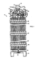
- the fuel assembly illustrated therein and generally designated with reference numeral 10 is of the type used in pressurized water reactors (PWR), such as the one diagrammatically illustrated in simplified form in Fig. 10 and designated with numeral 12.
- PWR pressurized water reactors
- the fuel assembly 10 comprises a lower end structure or bottom nozzle 14 for supporting the assembly 10 on the lower core plate (not shown) in the core 16 of the PWR 12, guide tubes or thimbles 18 extending longitudinally upward from the bottom nozzle 14, transverse grids 20 axially spaced along the guide thimbles 18, an organized array of fuel rods 22 transversely spaced and supported by the grids 20, an instrumentation tube 24 located in the center of the fuel assembly, and an upper end structure or top nozzle 26 attached to the upper ends of the guide thimbles 18.
- the fuel assembly 10 forms an integral unit capable of being conventionally handled without damage to its assembly parts.
- each of the fuel rods 22 contains nuclear fuel pellets (not shown) composed of fissile material, and has its opposite ends sealed.
- a primary liquid moderator/coolant such as water, held under a sufficiently high pressure (e.g. at 153 atm.) to keep it in liquid form, is pumped through the fuel assemblies 10 of the core 16 in order to extract heat generated therein.
- a sufficiently high pressure e.g. at 153 atm.
- the primary coolant is circulated by a primary pump 31 through a closed primary path 32 which leads through a first chamber 33 of a heat exchanger 34 where the extracted heat is given up to a secondary flow of water circulated by a secondary pump 35 through a closed secondary path 36 which leads through a second chamber 37 of the heat exchanger 34 where the water in the secondary path is turned into steam used to drive a turbine 38 for generating electricity.
- a number of control rods (not shown) reciprocally movable in some of the guide thimbles 18 can be employed to partially effectuate excess reactivity control but full control usually is achieved, as mentioned earlier herein, by additional means such as through spectral shift involving the displacement of moderator water to reduce excess reactivity at an early stage of the core operating cycle, and the subsequent removal of the moderator displacement to increase the reactivity.
- the apparatus according to the present invention and the one embodying the invention claimed in Applicant's copending application mentioned above are designed to permit spectral shift to be implemented in existing reactors and on a reusable basis.
- the top nozzle 26 comprises a transversely extending adapter plate 40 and upright sidewalls 42 connected to the plate 40 at its periphery and extending therefrom upwards so as to define an enclosure or housing 44.
- an annular flange 46 Connected to the top of the sidewalls 42 is an annular flange 46 adapted to have clamped thereto leaf springs (not shown) which cooperate with the upper core plate (not shown) of the reactor core 16 to prevent hydraulic lifting of the fuel assembly 10 while allowing for changes in fuel assembly length, as well known in the art.
- the spectral shift apparatus embodying the invention and generally designated with numeral 48 is disposed within the housing 44 of the top nozzle 26 and extends into some of the guide thimbles 18.
- the spectral shift apparatus 48 includes a plurality of water displacer rods 50 adapted to be inserted into respective ones of the guide thimbles 18 of the fuel assembly 10 for the purpose of displacing a predetermined volume of the liquid neutron moderating coolant present in the assembly 10 and thereby reducing the hydrogen/uranium ratio, hence the reactivity level of the reactor core 16.
- Each of the displacer rods 50 consists of an elongate tubular body 51 which is sealed at its lower end with an end plug 52, has a flow opening 54 defined at its upper end, and contains a quantity of water W equivalent to a predetermined minor fraction, e.g. 15%, of the total volume of the rod 50.
- the spectral shift apparatus 48 also includes a manifold, generally designed with numeral 56, which interconnects the displacer rods 50 and is in fluid flow communication therewith.
- the manifold 56 is located atop the fuel assembly 10, being disposed within the top nozzle 26 and resting on its adapter plate 40 (see Fig. 1).
- the manifold 56 comprises a central inlet in the form of a tubular and preferably cylindrical member 58 which defines a central plenum 60 axially therethrough and has at its upper end a central inlet opening 62 which is in fluid flow communication with the plenum.
- the manifold 56 includes also a plurality of hollow tubular vanes 64 which are mounted on a hub 66 attached to the cylindrical member 58 and closing it at the lower end thereof.
- the vanes 64 which extend radially outward from the member 58 are in fluid flow communication with the central plenum 60 through radial flow channels 67 formed in the hub 66, and they are provided with openings 68 which form outlets of the manifold 56.
- the displacer rods 50 are connected, at their upper ends, to the various tubular vanes 64 such that the flow opening 54 of each displacer rod is in fluid flow communication with an outlet 68 of the manifold.
- the manifold 56 and the tubular vanes 64 serve as a support structure for the displacer rods.
- the spectral shift apparatus 48 further includes sealing means, generally designated 70, connected to the cylindrical member 58 of the manifold 56 and sealing the inlet opening 62 therein.
- the sealing means 70 comprises a rupturable disk 72, a baffle screen 74, and an annular cap 76, commercially available per se as standard off-the-shelf items.
- the disk 72 is selected to rupture at a given pressure differential thereacross. For instance, in order to avoid rupturing due to pressure variations caused by application of design duty cycle transients which at a maximum are not expected to be substantially above 100 atmospheres, the disk 72 could be designed to fail or rupture only if the pressure differential exceeds 120 atmospheres. As seen from Figs.
- the disk 72 is dished and is so mounted on the tubular member 58 that its convex side faces inward and its concave side faces outwards.
- the dished portion of the dish 72 is prescored to promote rupture in a particular direction, namely, inwardly of the central plenum 60 within the member 58, as illustrated in Fig. 7.
- the baffle screen 74 is placed over its concave or high-pressure side.
- the disk 72 and the screen 74 are sealingly but removably and replaceably mounted on the upper end of the cylindrical member 58 by means of the annular cap 76 which is internally threaded and removably connected to externally threaded upper end portion of the member 58 so as to permit a ruptured disk 72 to be eventually removed and replaced with a new one.
- FIG. 9 illustrating a displacer rod 50' having its own sealing means 70' comprising a rupturable disk 72', baffle screen 74', and annular cap 76' each performing the same functions as the corresponding parts of the sealing means 70 described above.
- This arrangement has the advantage that if one of the seals in the apparatus fails prematurely, the effect of its failure will be less noticeable from a power peaking and reactivity insertion viewpoint than the effect of failure of a common seal resulting in flooding of all displacer rods.
- the common sealed plenum approach is appealing because of the lesser number of parts and greater simplicity with regard to refurbishment. Practitioners no doubt will base their ultimate choice between these two different-approaches upon considerations regarding trade-offs of seal reliability, power peaking, and other factors. Regardless of the approach chosen (i.e., single seal or multiple seals), the seal is designed to rupture on demand and to provide the flooding of the displacer rods 50 when desired.
- a separate spectral shift apparatus is employed with each of a desired number of fuel assemblies 10 in the core 16.
- the various spectral shift apparatus 48 are positioned upon the respective fuel assemblies 10 such that their displacer rods 50 extend into guide thimbles 18.
- the displacer rods 50 When thus positioned, the displacer rods 50 are disposed in the closed primary flow path 32 of the primary moderator/coolant and consequently they displace a predetermined volume of the primary moderator/coolant according to their size, thereby causing the spectrum of nuclear reactivity produced by the fuel rods 22 in the core 16 to be shifted from an excessively high, initial level down to a lower level.
- the power of the reactor core 16 is elevated to its normal operating level, ordinarily through manipulation of the control rods (not shown), and the primary pump 31 is operated to increase the pressure of the primary moderator/coolant in the flow path 32 likewise to a normal operating level.
- the pressure of the water within the displacer rods 50 is also elevated, and the pressure differential across the rupturable disk 72, based upon the pressure of the water within the sealed displacer rods 50 relative to the pressure of the primary moderator/coolant, will typically be 78 atm. or less.
- the disk 72 is designed to withstand pressure variations due to operating transients up to approximately 120 atmospheres.
- the following unique operational transient is imposed while maintaining the pressure of the primary moderator/coolant at its normal operating level of approximately 150 atmospheres.
- the reactor power is decreased to about two percent of the normal operating level, with the turbine 38 being taken off-line and the reactor core 16 being made subcritical by an amount of reactivity equivalent to the maximum reactivity that could be added by rupture of the disk 72 and flooding of the rods 50.
- the primary coolant temperature is reduced to 190-205°C by dropping steam pressure. At about 205°C, the saturation pressure inside each of the rods 50 is approximately 17 atm.
- the differential pressure across the rupturable disk 72 is approximately 135 atmospheres, i.e. above the predetermined differential of 120 atm. at which the disk is designed to rupture.
- the disk 72 will rupture and the displacer rods 50 consequently will become flooded, means in the form of a flow restrictor 78 (see Fig. 8) preferably being provided in the upper portion of the tubular body 51 of each displacer rod 50 to restrict the rate of moderator/coolant flow into the body 51.
- a flow restrictor 78 see Fig. 8 preferably being provided in the upper portion of the tubular body 51 of each displacer rod 50 to restrict the rate of moderator/coolant flow into the body 51.
- Flooding of the displacer rods 50 with moderating coolant produces a reverse spectral shift which returns the reactivity to the desired higher level. After this reverse spectral shift, the reactor core 16 is returned to normal power.
- the apparatus 48 should be equipped with the apparatus 48, such as, for example, all fuel assemblies having no control rod assemblies associated therewith.
- refurbishment of the apparatus 48 consisting in draining the rods 50 and replacing the ruptured disks 72, preferably should be done off-line.
- the removed spectral shift apparatus can be taken to a fuel storage area and readied for installation during a subsequent refueling stop.
- Temporary storage of the apparatuses can be made in the stored fuel. An apparatus lifetime of 3-5 cycles appears to be feasible.
- the refurbishing apparatus embodying the present invention and generally designated with numeral 80 is particularly well adapted for use in conjunction with the apparatus 48 described above. More specifically, the refurbishing apparatus 80 is used to remove or drain from the displacer rods 50 the moderator/coolant with which they were flooded for the purpose of effecting a reverse spectral shift.
- the refurbishing apparatus 80 comprises a plurality of first and second ports 82, 84 formed in the central cylindrical member 58, a pair of first and second conduits 86, 88 extending between the cylindrical member 58 and each respective displacer rod 50, and a generally cylindrical refurbishing tool 90 insertable in the central plenum 60 of the cylindrical member 58. While only two pairs of the first and second conduits 86, 88 are seen in Figs. 1, 2 and 8, it should be understood that for each of the displacer rods there is provided a separate pair of conduits 86, 88.
- first and second ports 82, 84 which are holes in wall portions of the cylindrical member 58 are vertically displaced with respect to one another and both communicate with the central plenum 60.
- Each pair of first and second conduits 86, 88 in the form of thin elongate capillary tubes, establishes fluid flow communication between the respective pair of first and second ports 82, 84 and upper and lower portions 92, 94 respectively of the associated displacer rods 50.
- the first and second conduits 86, 88 extend from the first and second ports 82, 84 radially outward along a respective tubular vane 64 to locations above the respective displacer rod 50 associated with the particular pair of conduits.
- the conduits are bent ninety degrees downward to extend through the vane 64 and through the upper flow opening 54 of the rod 50.
- the first conduit 86 terminates within the upper portion 92 of the rod 50 a relatively short distance below the vane 64
- the second conduit 88 extends through the flow restrictor 78 and terminates within the lower portion 94 of the rod 50 a relatively short distance above the lower end plug 52 thereof.
- the charging tool 90 has formed therein first and second flow passageways 96, 98 with corresponding first and second flow openings 100, 102.
- Means in the form of 0-rings 104, 106, 107 are provided which are effective, when the charging tool 90 is inserted in the cylindrical member 58, to form therebetween seals placing the first and second flow openings 100, 102 in separate fluid flow communication respectively with the first and second ports 92, 94 of the cylindrical member 58.
- the 0-rings 104, 106, 107 are disposed on the interior wall of cylindrical member 58, with the first 0-ring 104 disposed above the first port 82, the second 0-ring 106 disposed between the ports 82 and 84, and the third 0-ring 107 disposed below the second port 84.
- the first conduit 86 together with first flow passageway 96 will provide an entrance path for air to the upper portion 92 of the displacer rod 50, and the second conduit 88 together with the second flow passageway 98 will provide an exit path, separate from the entrance path, for moderator/coolant, such as water, from the lower portion 94 of the rod 50.
- the water within the rod 50 can be removed by introducing air under pressure through the entrance path into the upper rod portion 92, and thereby forcing water from the lower rod portion 94 out through the exit path until the water level within the hollow rod 50 has dropped to the level of the lower end 108 of the second conduit 88 whereupon further removal of water will automatically cease.
- the end 108 of the second conduit :88 is spaced from the bottom of the rod 50 a distance such as to leave in the rod a quantity of water W equivalent to a minor fraction of approximately fifteen percent of the rod volume.
- each displacer rod would then be formed by the passageway 96 of the refurbishing tool 90, the respective flow channel 67 of the hub 66, and the respective tubular vanes 64 associated therewith, whereas the exit path will be the same as described hereinbefore, namely, the path through conduit 88, port 84, and flow passageway 98.
Landscapes
- Physics & Mathematics (AREA)
- Engineering & Computer Science (AREA)
- Plasma & Fusion (AREA)
- High Energy & Nuclear Physics (AREA)
- General Engineering & Computer Science (AREA)
- Chemical Kinetics & Catalysis (AREA)
- Chemical & Material Sciences (AREA)
- Spectroscopy & Molecular Physics (AREA)
- Monitoring And Testing Of Nuclear Reactors (AREA)
- Extraction Or Liquid Replacement (AREA)
- Liquid Carbonaceous Fuels (AREA)
- Spectrometry And Color Measurement (AREA)
- Optical Communication System (AREA)
- Cash Registers Or Receiving Machines (AREA)
Applications Claiming Priority (2)
| Application Number | Priority Date | Filing Date | Title |
|---|---|---|---|
| US701052 | 1985-02-12 | ||
| US06/701,052 US4728480A (en) | 1985-02-12 | 1985-02-12 | Apparatus and method for refurbishing a spectral shift mechanism for a nuclear reactor fuel assembly |
Publications (3)
| Publication Number | Publication Date |
|---|---|
| EP0191430A2 true EP0191430A2 (de) | 1986-08-20 |
| EP0191430A3 EP0191430A3 (en) | 1987-08-19 |
| EP0191430B1 EP0191430B1 (de) | 1990-05-09 |
Family
ID=24815873
Family Applications (1)
| Application Number | Title | Priority Date | Filing Date |
|---|---|---|---|
| EP86101594A Expired - Lifetime EP0191430B1 (de) | 1985-02-12 | 1986-02-07 | Vorrichtung und Verfahren zur Instandhaltung des Spektrumverschiebungsapparates eines Kernbrennelements |
Country Status (7)
| Country | Link |
|---|---|
| US (1) | US4728480A (de) |
| EP (1) | EP0191430B1 (de) |
| JP (1) | JPS61186893A (de) |
| KR (1) | KR940003707B1 (de) |
| CN (1) | CN86101049A (de) |
| DE (1) | DE3671126D1 (de) |
| ES (1) | ES8801467A1 (de) |
Cited By (1)
| Publication number | Priority date | Publication date | Assignee | Title |
|---|---|---|---|---|
| EP0300745A2 (de) * | 1987-07-23 | 1989-01-25 | Mitsubishi Atomic Power Industries, Inc | Reaktivitätsregelmethode für Leichtwassergekühlte und leichtwassermoderierte Kernreaktorspaltzone und Apparat hierfür |
Families Citing this family (7)
| Publication number | Priority date | Publication date | Assignee | Title |
|---|---|---|---|---|
| DE4006264A1 (de) * | 1990-02-28 | 1991-08-29 | Siemens Ag | Siedewasserkernreaktor und kernreaktorbrennelement fuer diesen siedewasserkernreaktor |
| US5200138A (en) * | 1991-08-05 | 1993-04-06 | Westinghouse Electric Corp. | Spectral shift-producing subassembly for use in a nuclear fuel assembly |
| US5416813A (en) * | 1992-10-30 | 1995-05-16 | Kabushiki Kaisha Toshiba | Moderator rod containing burnable poison and fuel assembly utilizing same |
| JP2009085378A (ja) * | 2007-10-01 | 2009-04-23 | Nippon Petroleum Refining Co Ltd | 配管補修具 |
| CN102117668B (zh) * | 2009-12-31 | 2014-08-27 | 中国核动力研究设计院 | 堆芯卸料工具 |
| EP3506318B1 (de) * | 2010-04-23 | 2020-10-14 | Atomic Energy of Canada Limited/ Énergie Atomique du Canada Limitée | Druckrohrreaktor und verfahren zum betrieb desselben |
| CN107866814B (zh) * | 2017-12-13 | 2020-02-28 | 清华大学 | 用于球床反应堆堆芯腔内构件视觉检测的机器人装置 |
Citations (5)
| Publication number | Priority date | Publication date | Assignee | Title |
|---|---|---|---|---|
| NL278799A (de) * | 1961-05-24 | |||
| FR2498800A1 (fr) * | 1981-01-23 | 1982-07-30 | Westinghouse Electric Corp | Reacteur nucleaire comportant un dispositif perfectionne de commande de moderation |
| FR2523358A1 (fr) * | 1982-03-11 | 1983-09-16 | Westinghouse Electric Corp | Reacteur nucleaire avec moderation de l'energie des neutrons |
| GB2160698A (en) * | 1984-06-22 | 1985-12-24 | Westinghouse Electric Corp | Moderator control apparatus for a nuclear reactor fuel assembly |
| EP0167069A1 (de) * | 1984-07-02 | 1986-01-08 | Westinghouse Electric Corporation | Spektrumverschiebungsreaktor mit Gasverdrängung |
Family Cites Families (16)
| Publication number | Priority date | Publication date | Assignee | Title |
|---|---|---|---|---|
| US341555A (en) * | 1886-05-11 | Combined venting and draft tube | ||
| US558207A (en) * | 1896-04-14 | Oil-can | ||
| NL112156C (de) * | 1956-08-07 | |||
| GB827321A (en) * | 1957-04-25 | 1960-02-03 | Atomic Energy Authority Uk | Improvements in or relating to sealing devices |
| GB916324A (en) * | 1958-04-25 | 1963-01-23 | Rolls Royce | Improvements in or relating to nuclear reactors |
| US3031393A (en) * | 1960-09-14 | 1962-04-24 | Albert J Saur | Coupled diaphragm nuclear reactor safety device |
| NL122958C (de) * | 1963-05-28 | |||
| GB1029712A (en) * | 1964-02-11 | 1966-05-18 | Atomic Energy Authority Uk | Improvements in or relating to nuclear reactors |
| DE1204347B (de) * | 1964-09-17 | 1965-11-04 | Rolf Schlottau | Verfahren zur Kompensation des Abbrandes in einem Kernreaktor mit Feststoffmoderator |
| BE673748A (de) * | 1964-12-14 | |||
| LU56354A1 (de) * | 1968-04-05 | 1968-10-04 | ||
| US4032401A (en) * | 1972-06-30 | 1977-06-28 | Westinghouse Electric Corporation | Combined solid and liquid system for controlling nuclear reactors |
| US4432934A (en) * | 1980-12-16 | 1984-02-21 | Westinghouse Electric Corp. | Displacer rod for use in a mechanical spectral shift reactor |
| ZA818395B (en) * | 1980-12-16 | 1983-07-27 | Westinghouse Electric Corp | Spectral shift reactor |
| US4497334A (en) * | 1982-07-12 | 1985-02-05 | Wolf Leo H | Cleaning apparatus for liquid delivery systems |
| US4661306A (en) * | 1984-07-02 | 1987-04-28 | Westinghouse Electric Corp. | Fluid moderator control system reactor internals distribution system |
-
1985
- 1985-02-12 US US06/701,052 patent/US4728480A/en not_active Expired - Fee Related
-
1986
- 1986-02-06 CN CN198686101049A patent/CN86101049A/zh active Pending
- 1986-02-07 DE DE8686101594T patent/DE3671126D1/de not_active Expired - Fee Related
- 1986-02-07 EP EP86101594A patent/EP0191430B1/de not_active Expired - Lifetime
- 1986-02-11 ES ES551827A patent/ES8801467A1/es not_active Expired
- 1986-02-12 JP JP61027018A patent/JPS61186893A/ja active Pending
- 1986-02-12 KR KR1019860000955A patent/KR940003707B1/ko active IP Right Grant
Patent Citations (5)
| Publication number | Priority date | Publication date | Assignee | Title |
|---|---|---|---|---|
| NL278799A (de) * | 1961-05-24 | |||
| FR2498800A1 (fr) * | 1981-01-23 | 1982-07-30 | Westinghouse Electric Corp | Reacteur nucleaire comportant un dispositif perfectionne de commande de moderation |
| FR2523358A1 (fr) * | 1982-03-11 | 1983-09-16 | Westinghouse Electric Corp | Reacteur nucleaire avec moderation de l'energie des neutrons |
| GB2160698A (en) * | 1984-06-22 | 1985-12-24 | Westinghouse Electric Corp | Moderator control apparatus for a nuclear reactor fuel assembly |
| EP0167069A1 (de) * | 1984-07-02 | 1986-01-08 | Westinghouse Electric Corporation | Spektrumverschiebungsreaktor mit Gasverdrängung |
Cited By (2)
| Publication number | Priority date | Publication date | Assignee | Title |
|---|---|---|---|---|
| EP0300745A2 (de) * | 1987-07-23 | 1989-01-25 | Mitsubishi Atomic Power Industries, Inc | Reaktivitätsregelmethode für Leichtwassergekühlte und leichtwassermoderierte Kernreaktorspaltzone und Apparat hierfür |
| EP0300745A3 (de) * | 1987-07-23 | 1990-02-07 | Mitsubishi Atomic Power Industries, Inc | Reaktivitätsregelmethode für Leichtwassergekühlte und leichtwassermoderierte Kernreaktorspaltzone und Apparat hierfür |
Also Published As
| Publication number | Publication date |
|---|---|
| KR860006795A (ko) | 1986-09-15 |
| ES8801467A1 (es) | 1987-12-16 |
| DE3671126D1 (de) | 1990-06-13 |
| CN86101049A (zh) | 1987-02-18 |
| EP0191430A3 (en) | 1987-08-19 |
| EP0191430B1 (de) | 1990-05-09 |
| US4728480A (en) | 1988-03-01 |
| KR940003707B1 (ko) | 1994-04-27 |
| ES551827A0 (es) | 1987-12-16 |
| JPS61186893A (ja) | 1986-08-20 |
Similar Documents
| Publication | Publication Date | Title |
|---|---|---|
| US3462345A (en) | Nuclear reactor rod controller | |
| US3775246A (en) | Reactor refueling method | |
| US5265136A (en) | Sodium cooled fast reactor | |
| CA1175162A (en) | Displacer rod for use in a mechanical spectral shift reactor | |
| EP2924690B1 (de) | Kernreaktor mit flüssigmetallkältemittel | |
| EP0191430B1 (de) | Vorrichtung und Verfahren zur Instandhaltung des Spektrumverschiebungsapparates eines Kernbrennelements | |
| US4696792A (en) | Nuclear reactor coolant recirculation | |
| EP0191429A2 (de) | Anordnung und Verfahren zur Spektrumverschiebung für Brennstoffbündel eines Kernreaktors | |
| EP0167069B1 (de) | Spektrumverschiebungsreaktor mit Gasverdrängung | |
| EP3482398B1 (de) | Kernreaktor mit einem erhöten wärmetauscher | |
| EP0175455B1 (de) | Kernreaktorregelstab mit verminderter Wirksamkeit an seiner Spitze | |
| EP0526753B1 (de) | Teilbündel zur Erzeugung einer Spektralverschiebung in einem Kernbrennstabbündel | |
| US4657726A (en) | Moderator control apparatus for a nuclear reactor fuel assembly | |
| US5139735A (en) | Reactivity control system | |
| EP0170943A2 (de) | Kernbrennelement mit Spektralverschiebungsstäben | |
| US5471513A (en) | Split control rod drive | |
| EP1202289B1 (de) | Kerntragstruktur für einen F-Gitter-Kern eines Siedewasser-Kernreaktors | |
| US4728487A (en) | Standardized reduced length burnable absorber rods for a nuclear reactor | |
| EP0152206A2 (de) | Radialer Neutronenreflektor | |
| US5227128A (en) | Reactivity controlled fuel assembly | |
| US4732729A (en) | Fast breeder reactor | |
| US3912582A (en) | Hydraulic balancing of a control component within a nuclear reactor | |
| JP3154840B2 (ja) | 反射体制御方式の原子炉 | |
| JPH0618688A (ja) | 活性流損失のないウォーターロッド | |
| EP0168671B1 (de) | Verbindungsanordnung für Brennstoffbündel eines Flüssigmoderatorregelsystems |
Legal Events
| Date | Code | Title | Description |
|---|---|---|---|
| PUAI | Public reference made under article 153(3) epc to a published international application that has entered the european phase |
Free format text: ORIGINAL CODE: 0009012 |
|
| AK | Designated contracting states |
Kind code of ref document: A2 Designated state(s): BE DE FR GB IT SE |
|
| PUAL | Search report despatched |
Free format text: ORIGINAL CODE: 0009013 |
|
| AK | Designated contracting states |
Kind code of ref document: A3 Designated state(s): BE DE FR GB IT SE |
|
| 17P | Request for examination filed |
Effective date: 19880119 |
|
| 17Q | First examination report despatched |
Effective date: 19890828 |
|
| GRAA | (expected) grant |
Free format text: ORIGINAL CODE: 0009210 |
|
| PGFP | Annual fee paid to national office [announced via postgrant information from national office to epo] |
Ref country code: FR Payment date: 19900427 Year of fee payment: 6 |
|
| AK | Designated contracting states |
Kind code of ref document: B1 Designated state(s): BE DE FR GB IT SE |
|
| PG25 | Lapsed in a contracting state [announced via postgrant information from national office to epo] |
Ref country code: IT Free format text: LAPSE BECAUSE OF FAILURE TO SUBMIT A TRANSLATION OF THE DESCRIPTION OR TO PAY THE FEE WITHIN THE PRE;WARNING: LAPSES OF ITALIAN PATENTS WITH EFFECTIVE DATE BEFORE 2007 MAY HAVE OCCURRED AT ANY TIME BEFORE 2007. THE CORRECT EFFECTIVE DATE MAY BE DIFFERENT FROM THE ONE RECORDED.SCRIBED TIME-LIMIT Effective date: 19900509 |
|
| ET | Fr: translation filed | ||
| REF | Corresponds to: |
Ref document number: 3671126 Country of ref document: DE Date of ref document: 19900613 |
|
| PGFP | Annual fee paid to national office [announced via postgrant information from national office to epo] |
Ref country code: DE Payment date: 19901217 Year of fee payment: 6 |
|
| PGFP | Annual fee paid to national office [announced via postgrant information from national office to epo] |
Ref country code: BE Payment date: 19910123 Year of fee payment: 6 |
|
| PGFP | Annual fee paid to national office [announced via postgrant information from national office to epo] |
Ref country code: SE Payment date: 19910228 Year of fee payment: 6 |
|
| PLBE | No opposition filed within time limit |
Free format text: ORIGINAL CODE: 0009261 |
|
| STAA | Information on the status of an ep patent application or granted ep patent |
Free format text: STATUS: NO OPPOSITION FILED WITHIN TIME LIMIT |
|
| 26N | No opposition filed | ||
| PG25 | Lapsed in a contracting state [announced via postgrant information from national office to epo] |
Ref country code: SE Effective date: 19920208 |
|
| PG25 | Lapsed in a contracting state [announced via postgrant information from national office to epo] |
Ref country code: BE Effective date: 19920228 |
|
| BERE | Be: lapsed |
Owner name: WESTINGHOUSE ELECTRIC CORP. Effective date: 19920228 |
|
| PG25 | Lapsed in a contracting state [announced via postgrant information from national office to epo] |
Ref country code: FR Effective date: 19921030 |
|
| PG25 | Lapsed in a contracting state [announced via postgrant information from national office to epo] |
Ref country code: DE Effective date: 19921103 |
|
| REG | Reference to a national code |
Ref country code: FR Ref legal event code: ST |
|
| EUG | Se: european patent has lapsed |
Ref document number: 86101594.9 Effective date: 19920904 |
|
| REG | Reference to a national code |
Ref country code: GB Ref legal event code: IF02 |
|
| PGFP | Annual fee paid to national office [announced via postgrant information from national office to epo] |
Ref country code: GB Payment date: 20050110 Year of fee payment: 20 |
|
| PG25 | Lapsed in a contracting state [announced via postgrant information from national office to epo] |
Ref country code: GB Free format text: LAPSE BECAUSE OF EXPIRATION OF PROTECTION Effective date: 20060206 |
|
| REG | Reference to a national code |
Ref country code: GB Ref legal event code: PE20 |