EP0168671B1 - Verbindungsanordnung für Brennstoffbündel eines Flüssigmoderatorregelsystems - Google Patents
Verbindungsanordnung für Brennstoffbündel eines Flüssigmoderatorregelsystems Download PDFInfo
- Publication number
- EP0168671B1 EP0168671B1 EP85107669A EP85107669A EP0168671B1 EP 0168671 B1 EP0168671 B1 EP 0168671B1 EP 85107669 A EP85107669 A EP 85107669A EP 85107669 A EP85107669 A EP 85107669A EP 0168671 B1 EP0168671 B1 EP 0168671B1
- Authority
- EP
- European Patent Office
- Prior art keywords
- fuel assembly
- support plate
- core support
- reactor according
- bellows
- Prior art date
- Legal status (The legal status is an assumption and is not a legal conclusion. Google has not performed a legal analysis and makes no representation as to the accuracy of the status listed.)
- Expired
Links
Images


Classifications
-
- G—PHYSICS
- G21—NUCLEAR PHYSICS; NUCLEAR ENGINEERING
- G21C—NUCLEAR REACTORS
- G21C3/00—Reactor fuel elements and their assemblies; Selection of substances for use as reactor fuel elements
- G21C3/30—Assemblies of a number of fuel elements in the form of a rigid unit
- G21C3/32—Bundles of parallel pin-, rod-, or tube-shaped fuel elements
- G21C3/34—Spacer grids
-
- G—PHYSICS
- G21—NUCLEAR PHYSICS; NUCLEAR ENGINEERING
- G21C—NUCLEAR REACTORS
- G21C7/00—Control of nuclear reaction
- G21C7/26—Control of nuclear reaction by displacement of the moderator or parts thereof by changing the moderator concentration
- G21C7/27—Spectral shift control
-
- Y—GENERAL TAGGING OF NEW TECHNOLOGICAL DEVELOPMENTS; GENERAL TAGGING OF CROSS-SECTIONAL TECHNOLOGIES SPANNING OVER SEVERAL SECTIONS OF THE IPC; TECHNICAL SUBJECTS COVERED BY FORMER USPC CROSS-REFERENCE ART COLLECTIONS [XRACs] AND DIGESTS
- Y02—TECHNOLOGIES OR APPLICATIONS FOR MITIGATION OR ADAPTATION AGAINST CLIMATE CHANGE
- Y02E—REDUCTION OF GREENHOUSE GAS [GHG] EMISSIONS, RELATED TO ENERGY GENERATION, TRANSMISSION OR DISTRIBUTION
- Y02E30/00—Energy generation of nuclear origin
- Y02E30/30—Nuclear fission reactors
Definitions
- This invention relates in general to the field of spectral shift pressurized water nuclear reactors and in particular to apparatus for seal connecting between fuel assemblies and the means used to provide the spectral shift control.
- the reactor core is designed to contain excess reactivity. As the reactor operates, the excess reactivity is gradually consumed until such point as the reactor core will no longer sustain the nuclear reaction and then the reactor must be refueled. Usually this occurs over a period of years. It is very advantageous to maximize the time between reactor refuelings (extend the life of the core) since refueling requires complete shutdown of the reactor and is quite time consuming. Extending the life of the core is usually accomplished by providing the core with a significant amount of excess reactivity.
- control over the fission process, or reactivity control including control necessitated by the excess reactivity is accomplished by varying the amounts of neutron-absorbing materials within the core of the reactor.
- Control rods which contain neutron-absorbing materials and are movable into and out of the core provide one method of controlling the reactivity.
- Burnable and nonburn- able poisons dissolved in the reactor coolant provide another method of reactivity control. As the reactivity decreases, due to reactor operation, the poisons are gradually removed by being burned by reactor operation or are physically removed by a separate system designed for such purpose. Most often, a combination of dissolved poisons and control rods are used to control the reactor and the excess reactivity.
- control with control rods and poisons absorb neutrons which could otherwise be used in a productive manner.
- the neutrons produced by the excess reactivity could be used to convert fertile materials within the fuel assemblies to plutonium or fissile uranium which can then be fissioned and contribute to an even further extension of core life.
- control rods and dissolved poisons provide very effective reactor control, their use comprises a relatively inefficient depletion of high cost uranium. It would be therefore, advantageous to control the excess reactivity, but not suppress the neutrons associated with the excess reactivity, in order to further extend core life or time between refuelings, and to lower fuel costs.
- One example of such method of control comprises a mechanical spectral shift reactor whereby hollow displacer rods are provided within fuel assemblies within the core (which, of course, displace) an equal volume of water within the fuel assemblies) and which are mechanically withdrawn or punctured to accomplish water flooding of the available volume (EP-A-0 054 238).
- the neutron spectrum is hardened by the displacement of a portion of the water within the core by the displacer rods.
- the spectrum is later softened by the addition of water within the core by the aforesaid rod withdrawal or puncturing.
- heavy water or deuterium oxide may be utilized to replace an equivalent volume of core water during the early stages of core life then to gradually reduce the volume of heavy water and replace it with regular reactor coolant (lightwater) during the later stages of core life.
- the less effective moderator, heavy water allows for less fuel enrichment and a higher ratio of converting fertile material to fissile material which in combination provides for a reduction of fuel costs and an extension of core life.
- There is however a seal connector between the fuel element assembly and the lower core support plate which allows for the introduction of the heavy water replacing the light water moderator and the subsequent reintroduction of the moderator while effectuating a sealed connection between the fuel assemblies and the core support plate.
- Such seal connectors must provide for sealing to guard against sudden increases in reactivity and for a nonfixed or nonpermanent sealed connection because of the inaccessibility of the bottom of the fuel assembly during core fueling.
- a spectral shift reactor with a seal connector which minimizes the possibility of leakage into the connector so as to prevent an inadvertent increase in reactivity and especially a seal connector which is integral with the fuel assembly and allows for automatic connection upon positioning of the fuel assembly within the reactor core.
- the present invention resides in a spectral shift pressurized water nuclear reactor having one or more flow channels in a fuel assembly and one or more flow channels in a lower core support plate characterized in that a seal connector consisting of elongated members axially aligned having a flow channel therethrough is disposed between said fuel assembly and said core support plate, said elongated members having first and second tubular end portions which are spaced and sealingly interconnected by a bellows and having opposite ends for sealing engagement with said fuel assembly and said core support plate.
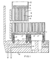
- a fuel assembly generally designated by the numeral 10 includes a plurality of fuel rods 11, an upper outlet flow nozzle 12, and a lower inlet flow nozzle 13.
- Fuel rods 11 are parallel arranged and may be held in spaced relationship to each other by Inconel grids (not shown) as is well known in the art.
- a plurality of moderator control tubes 14 are interspersed among fuel rods 11.
- the Inconel grids (not shown) also support and are attached to the moderator control tubes 14.
- Upper outlet flow nozzle 12 is fixedly attached to the upper end 15 of the moderator control tubes 14 as by welding.
- the lower inlet flow nozzle 13 is seal welded to the lower end 17 of the moderator flow tubes 14.
- Fuel assembly 10 is of a type used with a light water, pressurized nuclear reactor which utilizes the spectral shift concept by varying the amount of deuterium oxide or heavy water within the fuel assembly, thereby varying the amount of light water moderator within the core.
- the deuterium oxide enters the fuel assembly via the channels 19 in the lower core support plate 20, through inlet seal connector 21, to lower nozzle manifold 18.
- the deuterium oxide is then distributed to the moderator control tubes 14 which, upon rising to the upper nozzle manifold 16, displaces the light water therein.
- the deuterium oxide then flows down the return flow moderator tube 22 to outlet seal connector 23 to the outlet channel 24 in the lower core support plate 20.
- each seal connector 21 and 23 experiences the substantially same internal pressure. Moreover, since each seal connector 21 and 23 are located at the same axial core station, they each experience the same external pressure.
- the inlet seal connector 21 is exposed to virtually the same environment as the outlet seal connector 23, and, by adjusting the internal pressure of the deuterium oxide to that of the coolant moderator at the inlet to the fuel assembly 10, there is substantially no pressure differential between the internal portion and the external portion of the seal connectors 21 and 23. Because of the substantially similar operating environment of the seal connectors 21 and 23, each seal connector may be made precisely the same and can be interchangeable.
- seal connector 21 or 23 Details of seal connector 21 or 23 are shown in Figure 2. Notwithstanding the near zero pressure differential internal and external of the seal connector, they are made to be leak free in the unlikely event of the existence of a negative or a positive pressure differential. A positive pressure differential coupled with a leaking seal connector could result in an inadvertent increase in moderation by an unplanned reintroduction of moderator within the fuel assembly 10. Obviously, such a condition is undesirable. On the other hand, a negative pressure differential coupled with a leaking seal connector could result in an unplanned decrease in moderator which is also undesirable.
- Seal connector 21 or 23 in general and represented with reference sign 34 in Figure 2 comprises a static upper portion 30 which is connected to the inlet end of fuel assembly 10, a movable lower portion 31 which is inserted within an insert 32, in the lower core support plate 20, a bellows 33 connecting the upper 30 and lower 31 portions and a skirt connected to upper portion 30 and which encircles bellows 33.
- Flow channels 35 and 36 are provided within upper portion 30 and lower portion 31, respectively, for purposes of introducing deuterium oxide or any other fluid (liquid or gas) which is less effective in slowing down neutons than light water into the fuel assembly 10 or reintroducing the light water reactor coolant into said fuel assembly 10.
- seal connector 21 or 23 may be integral with or permanently affixed only at one end to either the lower nozzle 13 or the core support plate 20.
- the static upper portion 30 of seal connector 21 or 23 is integral with flow nozzle 13 while the movable lower portion 31 comprises a slip fit which is spring loaded within and against core support plate 20 by a combination of fuel assembly hold down spring forces, the weight of the fuel assembly and a bellows spring force to be described hereinafter.
- upper static portion 30 may be connected by a rolled bulge joint 37 within a boss or cylindrical extension 38 which is an integral part of lower nozzle 13.
- a plurality of rolled bulge joints 37 are provided so that a substantially leak free joint obtained between upper portion 30 and boss 38.
- the thin cylindrical portion 39 of static portion 30 is rolled into grooves 40 in the internal surface of boss 38.
- Another equally satisfactory and adequate mechanical connection may comprise a "Swage-lok" or other similar type of tube to housing connection.
- Still another type of seal joint may comprise threading upper portion 30 into boss 38 and seal welding around the periphery thereof provided the materials used are capable of being welded.
- One method to effectuate the seal between the movable portion 31 of seal connector 21 or 23 and the lower core support plate 20 comprises a ball and cone seal 50 in combination with a plurality of "piston ring" seals 51.
- insert 32 is inserted within an opening 53 in core support plate 20 and is welded at 54 thereto.
- Weld 54 serves as a mechanical and a sealing joint, with the latter being necessitated because of the need for opening 53 to be flow connected to either flow channel 19 or 24 in core support plate 20, which in turn provides flow communication between the flow channels 35 and 36 in seal connector 21 or 23.
- Ball and cone seal 50 employs principles which are well known in the art.
- a truncated conical surface 56 is provided at the upper end of insert 32.
- Surface 56 may be directly machined in insert 32 or may comprise a conical insert 57 made of a material substantially harder than the material from which lower portion 31 of seal connector 21 or 23 is made which is welded to lower portion 31 and then machined to final dimensions. While being slightly more complicated, the conical insert 57 is preferable in that it negates the probability of damage to the insert 32 integral with the lower core support plate 20.
- Movable portion 31 of the seal connector 21 or 23 includes a machined truncated spherical surface 58 which sealingly mates with conical surface 56.
- a plunger 59 extends from movable portion 31 and has a plurality of piston ring seals 51 fitted to grooves 60 machined in the periphery thereof. Ring seals 51 are of any design which is well known in the art and serve as a backup seal to limit any leakage into or out from the moderator control tubes 14 in the event that the main ball and cone seal 50 is damaged or otherwise fails to operate properly.
- a bellows 33 sealingly connects lower portion 31 to upper portion 30 of seal connector 21 or 23.
- Bellows 33 is made of metal and is welded at 52 and 55 to a cylindrical extension 61 from upper portion 30 and a cylindrical extension 62 from lower portion 31.
- Clearance space 63 is provided between upper 30 and lower 31 portions of the seal connector. Clearance space 63 allows for relative axial motion between the upper 30 and lower portions 31 which motion allows for a compressive load to be applied to fuel assembly 10 when installed in the reactor core and assures positive sealing of spherical surface 58 within conical surface 56.
- bellows 33 comprises a spring which transmits its compressive force, the compressive spring force applied to fuel assembly 10 and the weight of the fuel assembly to the lower portion 31 of seal connector 21 or 23.
- Metallic bellows 33 and clearance space 63 also allows for proper sealing notwithstanding any slight misalignment perpendicular to the axial centerline of the seal connector 21 or 23.
- Skirt provides protection for bellows 33 and serves as an additional stop to limit the compressive travel of the movable lower portion 31 relative to the upper portion 30.
- Skirt comprises a cylindrical tube 64 welded at 65 to an enlarged cylindrical portion 66 of the static upper portion 30. Skirt extends down from said weld 65 covering the bellows 33 and terminates at end 67 which is spaced from insert 52 by a predetermined amount 68.
- seal connector 21 or 23 comprises a mechanically connected extension of a fuel assembly 10. Insert 32 is fixedly connected to core support plate 20. In the event seal connector 21 or 23 is damaged, it may be removed from fuel assembly 10 and replaced with a new seal connector. During such replacement, fuel assembly 10 is of course not assembled within a reactor core.
- Plunger 59 is further provided with a tapered entrance end 71 in the unlikely event of any misalignment of the fuel assembly 10 relative to core support plate 20. Taper 71 even further provides for minor misalignment, if any, of plunger 59 relative to opening 72 within insert 32. The transverse motion permitted by bellows 33, as previously described, then assures full sealing along the length of plunger 59. Contact between spherical surface 58 and conical surface 56 is effectuated after plunger 59 is substantially fully fitted within opening 72.
- FIG. 3 Another embodiment of a seal connector 80 is shown in Figure 3. In general, this embodiment differs from that of Figure 2 by the provision of one or more ring seals 81 between the static portion 82 and the movable portion 83 of the seal connector 80. Ring seals 81 provide a backup seal in the unlikely event of failure of bellows 84. Ring seals 81 are fitted to grooves within end 85 of static portion 82; end 85 fits within an extension 86 of movable portion 83 which has an opening 87 therein and overlaps end 85.
- FIG. 3 Further illustrated in Figure 3 is an alternate method of attaching the static portion 82 to the lower nozzle 13.
- a flow connector 88 is inserted within an opening 89 in the lower nozzle 13. Opening 89 is in flow communication with either the lower nozzle manifold 18 and moderator control tube 22 ( Figure 1) depending upon whether seal connector 80 comprises an inlet connector or an outlet connector, respectively.
- Flow connector 88 is welded at 90 to lower nozzle 13.
- An extension 91 of the flow connector 88 fits within the upper end 92 of the static portion 82 of seal connector 80.
- static portion 82 is integrally seal connected to flow connector 88 by a plurality of rolled joints 93. As previously discussed, such connection may also comprise a "Swage-lok" type of connection.
Landscapes
- Physics & Mathematics (AREA)
- Engineering & Computer Science (AREA)
- Plasma & Fusion (AREA)
- General Engineering & Computer Science (AREA)
- High Energy & Nuclear Physics (AREA)
- Spectroscopy & Molecular Physics (AREA)
- Chemical & Material Sciences (AREA)
- Chemical Kinetics & Catalysis (AREA)
- Monitoring And Testing Of Nuclear Reactors (AREA)
- Examining Or Testing Airtightness (AREA)
Claims (8)
Applications Claiming Priority (2)
| Application Number | Priority Date | Filing Date | Title |
|---|---|---|---|
| US62694284A | 1984-07-02 | 1984-07-02 | |
| US626942 | 1984-07-02 |
Publications (2)
| Publication Number | Publication Date |
|---|---|
| EP0168671A1 EP0168671A1 (de) | 1986-01-22 |
| EP0168671B1 true EP0168671B1 (de) | 1989-05-24 |
Family
ID=24512507
Family Applications (1)
| Application Number | Title | Priority Date | Filing Date |
|---|---|---|---|
| EP85107669A Expired EP0168671B1 (de) | 1984-07-02 | 1985-06-21 | Verbindungsanordnung für Brennstoffbündel eines Flüssigmoderatorregelsystems |
Country Status (4)
| Country | Link |
|---|---|
| EP (1) | EP0168671B1 (de) |
| JP (1) | JPS6120884A (de) |
| KR (1) | KR860001436A (de) |
| ES (1) | ES8702045A1 (de) |
Family Cites Families (5)
| Publication number | Priority date | Publication date | Assignee | Title |
|---|---|---|---|---|
| US3103475A (en) * | 1963-09-10 | Szilard | ||
| US2977297A (en) * | 1958-09-02 | 1961-03-28 | Ersel A Evans | Reactor fuel assembly |
| US3578563A (en) * | 1967-07-14 | 1971-05-11 | Electrodyne Res Corp | Fluid coolant apparatus for a nuclear reactor |
| US3725199A (en) * | 1969-04-09 | 1973-04-03 | Combustion Eng | Nuclear reactor organization and fuel assembly arrangement |
| CA1175164A (en) * | 1980-12-16 | 1984-09-25 | John F. Wilson | Mechanical spectral shift reactor |
-
1985
- 1985-06-21 EP EP85107669A patent/EP0168671B1/de not_active Expired
- 1985-06-27 JP JP60139250A patent/JPS6120884A/ja active Granted
- 1985-06-28 ES ES544695A patent/ES8702045A1/es not_active Expired
- 1985-07-02 KR KR1019850004751A patent/KR860001436A/ko not_active Withdrawn
Also Published As
| Publication number | Publication date |
|---|---|
| ES544695A0 (es) | 1986-12-01 |
| JPS6120884A (ja) | 1986-01-29 |
| JPH0243159B2 (de) | 1990-09-27 |
| KR860001436A (ko) | 1986-02-26 |
| EP0168671A1 (de) | 1986-01-22 |
| ES8702045A1 (es) | 1986-12-01 |
Similar Documents
| Publication | Publication Date | Title |
|---|---|---|
| US4285769A (en) | Control cell nuclear reactor core | |
| CN101223607B (zh) | 改进的灰棒控制组件 | |
| US4155807A (en) | Core and transition fuel assembly for a nuclear reactor | |
| US4420458A (en) | Nuclear fuel assembly with coolant conducting tube | |
| US3853702A (en) | Pressure vessel penetration technique | |
| EP0178604B1 (de) | Schneller Brutreaktor | |
| EP0167069B1 (de) | Spektrumverschiebungsreaktor mit Gasverdrängung | |
| Kambe et al. | RAPID-L operator-free fast reactor concept without any control rods | |
| US5200138A (en) | Spectral shift-producing subassembly for use in a nuclear fuel assembly | |
| US4708842A (en) | Fluid moderator control system fuel assembly seal connector | |
| US3573166A (en) | Hydraulic control rod drive system | |
| EP0158100B1 (de) | Giftstab zur Benutzung in einem Kernreaktor | |
| US3844883A (en) | Pressure vessel penetration techniques | |
| US4717527A (en) | Fuel assembly | |
| EP0168671B1 (de) | Verbindungsanordnung für Brennstoffbündel eines Flüssigmoderatorregelsystems | |
| US3816248A (en) | Nuclear fuel pin | |
| US4728487A (en) | Standardized reduced length burnable absorber rods for a nuclear reactor | |
| US4728480A (en) | Apparatus and method for refurbishing a spectral shift mechanism for a nuclear reactor fuel assembly | |
| US4684504A (en) | Bow resistant structural member for fuel assemblies in non-control rod locations of a nuclear reactor core | |
| US3844882A (en) | Lift piston assembly | |
| US3843471A (en) | Top actuated reactor control system | |
| US5610959A (en) | Hafnium doped replacement rod for nuclear fuel reconstitution | |
| EP0152206A2 (de) | Radialer Neutronenreflektor | |
| US4687627A (en) | Water displacer rod with hollow annular support pellets having sealed internal voids | |
| US4470947A (en) | Double-clad nuclear fuel safety rod |
Legal Events
| Date | Code | Title | Description |
|---|---|---|---|
| PUAI | Public reference made under article 153(3) epc to a published international application that has entered the european phase |
Free format text: ORIGINAL CODE: 0009012 |
|
| AK | Designated contracting states |
Designated state(s): BE CH FR GB IT LI |
|
| 17P | Request for examination filed |
Effective date: 19860611 |
|
| 17Q | First examination report despatched |
Effective date: 19871026 |
|
| ITF | It: translation for a ep patent filed | ||
| GRAA | (expected) grant |
Free format text: ORIGINAL CODE: 0009210 |
|
| AK | Designated contracting states |
Kind code of ref document: B1 Designated state(s): BE CH FR GB IT LI |
|
| PGFP | Annual fee paid to national office [announced via postgrant information from national office to epo] |
Ref country code: BE Payment date: 19890621 Year of fee payment: 5 |
|
| PGFP | Annual fee paid to national office [announced via postgrant information from national office to epo] |
Ref country code: CH Payment date: 19890627 Year of fee payment: 5 |
|
| ET | Fr: translation filed | ||
| PGFP | Annual fee paid to national office [announced via postgrant information from national office to epo] |
Ref country code: GB Payment date: 19890731 Year of fee payment: 5 |
|
| PLBE | No opposition filed within time limit |
Free format text: ORIGINAL CODE: 0009261 |
|
| STAA | Information on the status of an ep patent application or granted ep patent |
Free format text: STATUS: NO OPPOSITION FILED WITHIN TIME LIMIT |
|
| 26N | No opposition filed | ||
| PG25 | Lapsed in a contracting state [announced via postgrant information from national office to epo] |
Ref country code: GB Effective date: 19900621 |
|
| PG25 | Lapsed in a contracting state [announced via postgrant information from national office to epo] |
Ref country code: BE Effective date: 19900630 Ref country code: CH Effective date: 19900630 Ref country code: LI Effective date: 19900630 |
|
| BERE | Be: lapsed |
Owner name: WESTINGHOUSE ELECTRIC CORP. Effective date: 19900630 |
|
| GBPC | Gb: european patent ceased through non-payment of renewal fee | ||
| REG | Reference to a national code |
Ref country code: CH Ref legal event code: PL |
|
| PGFP | Annual fee paid to national office [announced via postgrant information from national office to epo] |
Ref country code: FR Payment date: 19920416 Year of fee payment: 8 |
|
| PG25 | Lapsed in a contracting state [announced via postgrant information from national office to epo] |
Ref country code: FR Effective date: 19940228 |
|
| REG | Reference to a national code |
Ref country code: FR Ref legal event code: ST |