EP0190965B1 - Vorrichtung für die Montage eines Wasserbelüfters im Auslauf eines Wasserhahns - Google Patents
Vorrichtung für die Montage eines Wasserbelüfters im Auslauf eines Wasserhahns Download PDFInfo
- Publication number
- EP0190965B1 EP0190965B1 EP19860400143 EP86400143A EP0190965B1 EP 0190965 B1 EP0190965 B1 EP 0190965B1 EP 19860400143 EP19860400143 EP 19860400143 EP 86400143 A EP86400143 A EP 86400143A EP 0190965 B1 EP0190965 B1 EP 0190965B1
- Authority
- EP
- European Patent Office
- Prior art keywords
- ring
- spray
- spout
- nebulizer
- tap
- Prior art date
- Legal status (The legal status is an assumption and is not a legal conclusion. Google has not performed a legal analysis and makes no representation as to the accuracy of the status listed.)
- Expired
Links
Images
Classifications
-
- B—PERFORMING OPERATIONS; TRANSPORTING
- B05—SPRAYING OR ATOMISING IN GENERAL; APPLYING FLUENT MATERIALS TO SURFACES, IN GENERAL
- B05B—SPRAYING APPARATUS; ATOMISING APPARATUS; NOZZLES
- B05B1/00—Nozzles, spray heads or other outlets, with or without auxiliary devices such as valves, heating means
- B05B1/22—Spouts
-
- E—FIXED CONSTRUCTIONS
- E03—WATER SUPPLY; SEWERAGE
- E03C—DOMESTIC PLUMBING INSTALLATIONS FOR FRESH WATER OR WASTE WATER; SINKS
- E03C1/00—Domestic plumbing installations for fresh water or waste water; Sinks
- E03C1/02—Plumbing installations for fresh water
- E03C1/08—Jet regulators or jet guides, e.g. anti-splash devices
- E03C1/084—Jet regulators with aerating means
Definitions
- the present invention relates to a device for fixing an aerator jet breaker in the spout of a tap.
- nebulizers which are in the form of a cylindrical housing, provided with slots, comprising a shoulder and a peripheral edge at one end and containing several grids arranged substantially in straight sections of said housing. .
- nebulizers are fixed using a shouldered nut screwed onto the end of the spout.
- the standards require that the water jet be directed in a predetermined direction.
- Document GB-A-1 160 996 describes a device for directing the jet.
- This device consists of a nebulizer forcibly engaged in the body of the valve and comprising, in particular a ring made of an elastically deformable material. This device does not allow the use of a commercial nebulizer of the kind described above.
- the device of the invention which comprises a ring forcibly engaged in the spout of the tap is characterized in that a conventional nebulizer is used, held by a ring made of an elastically deformable material, the locking of the ring being ensured by the introduction of said nebulizer into said ring, the latter comprising means such as notches to oppose the axial displacement of said nebulizer when the peripheral edge of the latter is applied against the corresponding end of said ring, the latter comprising means for oppose the axial displacement of said nebulizer.
- the spout of the tap has a spherical cavity with a constricted opening in which one engages, by elastic deformation, the aforementioned ring whose dimension of the internal diameter is intended to receive the nebulizer, the peripheral edge of the latter coming to bear against the end of the ring on which it is held by elastic deformation of locking members.
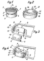
- the nebulizer designated by the reference 1 is constituted by a cylindrical housing having towards one end a portion of larger diameter 2 ending in a peripheral border 3.
- the housing In the housing are arranged grids such as those 4 which appear in the drawing.
- the housing also has, on its part 5 of smaller diameter than that of part 2, air inlet openings 6. In the use position, the water flows through the nebulizer in the direction of the arrow F1 ( Figure 1).
- a ring is used, made of an elastically deformable material, to fix the nebulizer 1 in the spout 7 of a tap.
- This ring an embodiment of which appears in FIG. 2 of the drawing, is designated by the general reference 8.
- the spout 7 to receive the nebulizer 1 has a spherical cavity 9 whose orifice 10 is constricted.
- the ring 8 has two distinct parts 11 and 12 separated by an annular groove 13.
- Part 11 forms a bead whose diameter is slightly greater than that of the cavity 9.
- Part 12 forms a skirt formed externally by a spherical surface whose radius is slightly less than that of the cavity 9.
- the diameter of the ring 8, measured at its end opposite to the bead 11, is less than the diameter of the orifice 10 of the beak.
- the inner diameter of the ring is substantially equal to that of part 2 of the nebulizer. In this way, by engaging the nebulizer in the ring 8, as shown in FIG. 3, said ring is locked in the spout 7.
- the latter has axial lugs 14, elastically deformable, forming towards the center of the ring and in combination with the end of the latter notches 15 coming to bear on the periphery of the border 3 of the nebulizer.
- the faces of the tabs 14 located towards the center of the ring 8 widen from the notches towards the end of said tabs.
Landscapes
- Health & Medical Sciences (AREA)
- Life Sciences & Earth Sciences (AREA)
- Engineering & Computer Science (AREA)
- Hydrology & Water Resources (AREA)
- Public Health (AREA)
- Water Supply & Treatment (AREA)
- Nozzles (AREA)
- Domestic Plumbing Installations (AREA)
- Containers And Packaging Bodies Having A Special Means To Remove Contents (AREA)
Claims (3)
Applications Claiming Priority (2)
| Application Number | Priority Date | Filing Date | Title |
|---|---|---|---|
| FR8501413 | 1985-02-01 | ||
| FR8501413A FR2576939B1 (fr) | 1985-02-01 | 1985-02-01 | Dispositif de fixation d'un brise-jet aerateur dans le bec d'un robinet |
Publications (2)
| Publication Number | Publication Date |
|---|---|
| EP0190965A1 EP0190965A1 (de) | 1986-08-13 |
| EP0190965B1 true EP0190965B1 (de) | 1988-04-20 |
Family
ID=9315852
Family Applications (1)
| Application Number | Title | Priority Date | Filing Date |
|---|---|---|---|
| EP19860400143 Expired EP0190965B1 (de) | 1985-02-01 | 1986-01-24 | Vorrichtung für die Montage eines Wasserbelüfters im Auslauf eines Wasserhahns |
Country Status (3)
| Country | Link |
|---|---|
| EP (1) | EP0190965B1 (de) |
| DE (1) | DE3660137D1 (de) |
| FR (1) | FR2576939B1 (de) |
Families Citing this family (13)
| Publication number | Priority date | Publication date | Assignee | Title |
|---|---|---|---|---|
| DE20216304U1 (de) * | 2002-10-22 | 2004-03-04 | Dieter Wildfang Gmbh | Sanitäre Auslaufarmatur |
| US8919680B2 (en) | 2002-10-22 | 2014-12-30 | Neoperl Gmbh | Functional plumbing unit |
| DK1554438T3 (da) | 2002-10-22 | 2010-04-12 | Neoperl Gmbh | Sanitært udløbsarmatur |
| DE10251362B4 (de) * | 2002-11-05 | 2011-01-27 | Neoperl Gmbh | Strahlregler |
| DE102004039915A1 (de) * | 2004-03-25 | 2005-10-27 | Kludi Gmbh & Co. Kg | Luftbeimischer einer Wasserarmatur |
| BRPI0507939A (pt) * | 2004-03-25 | 2007-07-31 | Neoperl Gmbh | aerador para uma torneira de água |
| DE102004018749B4 (de) * | 2004-04-17 | 2006-04-27 | Neoperl Gmbh | Auslaufelement für eine Sanitärarmatur |
| DE102005010550B4 (de) | 2005-03-04 | 2007-03-22 | Neoperl Gmbh | Sanitärer Wasserauslauf |
| DE202005016046U1 (de) * | 2005-10-13 | 2007-02-22 | Neoperl Gmbh | Sanitäres Einbauteil |
| BR112015022611B1 (pt) * | 2013-03-12 | 2021-10-13 | Neoperl Gmbh | Peça inserta em artefatos sanitários e processo de limpeza de uma malha rotativa em uma peça inserta em artefatos sanitários |
| EP2913447A1 (de) * | 2014-02-28 | 2015-09-02 | Mohanarajah Sithamparanathan | Am Wasserhahn montierbares Gerät |
| IT202000019291A1 (it) * | 2020-08-05 | 2022-02-05 | Nikles Inter AG | Dispositivo di erogazione di un fluido con valvola di sicurezza |
| CN118482220B (zh) * | 2024-05-13 | 2025-12-30 | 九牧厨卫股份有限公司 | 一种水龙头单元、水龙头及水龙头结构 |
Family Cites Families (6)
| Publication number | Priority date | Publication date | Assignee | Title |
|---|---|---|---|---|
| US2884418A (en) * | 1954-12-17 | 1959-04-28 | Syntex Sa | 19 nor spirostatriene and spirostatetraene intermediates |
| US2986341A (en) * | 1958-05-27 | 1961-05-30 | Wrightway Engineering Co | Pilfer proof aerating device |
| DE1658154A1 (de) * | 1967-02-23 | 1970-08-20 | Sanitaere Armaturen Rennert & | Auslaufvorrichtung fuer Wasserauslaeufe von sanitaeren Armaturen |
| GB1160996A (en) * | 1967-04-07 | 1969-08-13 | Barking Brassware | Improvements in or relating to Spray Nozzle Assemblies |
| CA1057647A (en) * | 1974-07-17 | 1979-07-03 | Alfred M. Moen | Flow control aerator |
| US3884418A (en) * | 1974-08-30 | 1975-05-20 | Cranda Corp | Aerating and spraying attachment for faucets |
-
1985
- 1985-02-01 FR FR8501413A patent/FR2576939B1/fr not_active Expired
-
1986
- 1986-01-24 DE DE8686400143T patent/DE3660137D1/de not_active Expired
- 1986-01-24 EP EP19860400143 patent/EP0190965B1/de not_active Expired
Also Published As
| Publication number | Publication date |
|---|---|
| FR2576939A1 (fr) | 1986-08-08 |
| EP0190965A1 (de) | 1986-08-13 |
| DE3660137D1 (en) | 1988-05-26 |
| FR2576939B1 (fr) | 1987-02-13 |
Similar Documents
| Publication | Publication Date | Title |
|---|---|---|
| EP0190965B1 (de) | Vorrichtung für die Montage eines Wasserbelüfters im Auslauf eines Wasserhahns | |
| EP0207114B1 (de) | Vorrichtung zum auftragen eines pastenartigen erzeugnisses, insbesondere eines kosmetischen erzeugnisses wie lippenstift, und rohrförmiges element für eine solche vorrichtung | |
| FR2831940A1 (fr) | Raccord rapide pour la jonction amovible de deux canalisations | |
| CH686470B5 (fr) | Boite de montre à lunette tournante. | |
| EP0884433B1 (de) | Verbindungseinrichtung für einen Treppenhandlauf | |
| CH631790A5 (fr) | Robinet a cartouche avec plaque rotative. | |
| FR2734152A1 (fr) | Dispositif de securite et de controle de verrouillage d'un moyeu de roue, notamment pour fauteuils roulants | |
| EP0230800A1 (de) | Mischventile | |
| FR2647863A1 (fr) | Ensemble d'ecrou a verrouillage | |
| FR2609968A2 (fr) | Dispositif a bec verseur escamotable et extensible | |
| EP0042523A2 (de) | Mischventil für sanitäre Anlagen | |
| EP0936128B1 (de) | Lenksystem, Lenkrad und Lenkradsäule für ein solches System | |
| FR2744081A1 (fr) | Dispositif d'essuie-glace, notamment pour un vehicule automobile, muni de moyens d'indexation de l'essuie-glace par rapport a un arbre d'entrainement | |
| EP0193437A1 (de) | Vorrichtung zum Befestigen eines Wasserhahnes an einer Wand | |
| FR2675858A1 (fr) | Dispositif de fixation de bobines d'electrovannes. | |
| BE1014865A3 (fr) | Dispositif de fixation amovible d'un aviron sur une | |
| FR2772819A1 (fr) | Semelle de reglage d'une gache de serrure de vehicule automobile | |
| EP3953050A1 (de) | Spender für druckbehälter | |
| EP0524105B1 (de) | Nichtabmontierbares Zwischenstück, insbesondere zum Einstellen der Orientierung von Fahrzeugscheinwerfern | |
| FR2607201A1 (fr) | Dispositif de fixation sur fut filete ou annele | |
| FR2479112A1 (fr) | Dispositif de reglage de l'ecartement d'une zone d'un ensemble tel qu'un projecteur par rapport a une zone d'un autre ensemble tel que la carrosserie d'un vehicule | |
| FR2656073A1 (fr) | Canal de guidage d'air avec un clapet. | |
| FR2738306A1 (fr) | Dispositif de fixation rapide d'une piece sur une embase, en particulier d'une electrovanne de machine a laver | |
| FR2528090A1 (fr) | Dispositif de vidage pour un appareil sanitaire | |
| WO2025238060A1 (fr) | Dispositif d'actionnement de chasse d'eau |
Legal Events
| Date | Code | Title | Description |
|---|---|---|---|
| PUAI | Public reference made under article 153(3) epc to a published international application that has entered the european phase |
Free format text: ORIGINAL CODE: 0009012 |
|
| AK | Designated contracting states |
Kind code of ref document: A1 Designated state(s): BE CH DE GB IT LI NL SE |
|
| 17P | Request for examination filed |
Effective date: 19860918 |
|
| 17Q | First examination report despatched |
Effective date: 19870406 |
|
| ITF | It: translation for a ep patent filed | ||
| GRAA | (expected) grant |
Free format text: ORIGINAL CODE: 0009210 |
|
| AK | Designated contracting states |
Kind code of ref document: B1 Designated state(s): BE CH DE GB IT LI NL SE |
|
| GBT | Gb: translation of ep patent filed (gb section 77(6)(a)/1977) | ||
| REF | Corresponds to: |
Ref document number: 3660137 Country of ref document: DE Date of ref document: 19880526 |
|
| PGFP | Annual fee paid to national office [announced via postgrant information from national office to epo] |
Ref country code: SE Payment date: 19890117 Year of fee payment: 4 |
|
| PGFP | Annual fee paid to national office [announced via postgrant information from national office to epo] |
Ref country code: NL Payment date: 19890131 Year of fee payment: 5 Ref country code: BE Payment date: 19890131 Year of fee payment: 4 |
|
| PGFP | Annual fee paid to national office [announced via postgrant information from national office to epo] |
Ref country code: CH Payment date: 19890203 Year of fee payment: 4 |
|
| PGFP | Annual fee paid to national office [announced via postgrant information from national office to epo] |
Ref country code: DE Payment date: 19890216 Year of fee payment: 4 |
|
| PLBE | No opposition filed within time limit |
Free format text: ORIGINAL CODE: 0009261 |
|
| STAA | Information on the status of an ep patent application or granted ep patent |
Free format text: STATUS: NO OPPOSITION FILED WITHIN TIME LIMIT |
|
| 26N | No opposition filed | ||
| PG25 | Lapsed in a contracting state [announced via postgrant information from national office to epo] |
Ref country code: GB Effective date: 19900124 |
|
| PG25 | Lapsed in a contracting state [announced via postgrant information from national office to epo] |
Ref country code: SE Effective date: 19900125 |
|
| PG25 | Lapsed in a contracting state [announced via postgrant information from national office to epo] |
Ref country code: LI Effective date: 19900131 Ref country code: CH Effective date: 19900131 Ref country code: BE Effective date: 19900131 |
|
| BERE | Be: lapsed |
Owner name: LES ROBINETS PRESTO Effective date: 19900131 |
|
| PG25 | Lapsed in a contracting state [announced via postgrant information from national office to epo] |
Ref country code: NL Effective date: 19900801 |
|
| NLV4 | Nl: lapsed or anulled due to non-payment of the annual fee | ||
| GBPC | Gb: european patent ceased through non-payment of renewal fee | ||
| REG | Reference to a national code |
Ref country code: CH Ref legal event code: PL |
|
| PG25 | Lapsed in a contracting state [announced via postgrant information from national office to epo] |
Ref country code: DE Effective date: 19901002 |
|
| EUG | Se: european patent has lapsed |
Ref document number: 86400143.3 Effective date: 19901107 |
|
| PG25 | Lapsed in a contracting state [announced via postgrant information from national office to epo] |
Ref country code: IT Free format text: LAPSE BECAUSE OF NON-PAYMENT OF DUE FEES;WARNING: LAPSES OF ITALIAN PATENTS WITH EFFECTIVE DATE BEFORE 2007 MAY HAVE OCCURRED AT ANY TIME BEFORE 2007. THE CORRECT EFFECTIVE DATE MAY BE DIFFERENT FROM THE ONE RECORDED. Effective date: 20050124 |