EP0190608B1 - Heel holding device - Google Patents
Heel holding device Download PDFInfo
- Publication number
- EP0190608B1 EP0190608B1 EP86100820A EP86100820A EP0190608B1 EP 0190608 B1 EP0190608 B1 EP 0190608B1 EP 86100820 A EP86100820 A EP 86100820A EP 86100820 A EP86100820 A EP 86100820A EP 0190608 B1 EP0190608 B1 EP 0190608B1
- Authority
- EP
- European Patent Office
- Prior art keywords
- heel clamp
- protective sheet
- detent member
- guide rail
- ski
- Prior art date
- Legal status (The legal status is an assumption and is not a legal conclusion. Google has not performed a legal analysis and makes no representation as to the accuracy of the status listed.)
- Expired - Lifetime
Links
Images

Classifications
-
- A—HUMAN NECESSITIES
- A63—SPORTS; GAMES; AMUSEMENTS
- A63C—SKATES; SKIS; ROLLER SKATES; DESIGN OR LAYOUT OF COURTS, RINKS OR THE LIKE
- A63C9/00—Ski bindings
- A63C9/005—Ski bindings with means for adjusting the position of a shoe holder or of the complete binding relative to the ski
Definitions
- the invention relates to a heel holder according to the first part of patent claim 1.
- AT-B-374 692 describes a device for the longitudinal adjustment of ski binding parts with a guide rail to be fastened to the ski, which is provided with two lateral guide strips and with two toothed strips arranged between them and extending in the longitudinal direction of the device, to which a locking element is assigned, which is under the influence of at least one with its other end on a guided on the guide rail, the heel holder carrying guide plate supported helical compression spring and which - seen from the side - has an approximately open U-shaped cross-section, the the web connecting the two legs carries the locking teeth.
- one leg of the locking member bears under the influence of the helical compression spring on a downwardly projecting shoulder of the guide plate, and the other leg can be locked in the raised position of the locking member, that is to say when the locking teeth are out of engagement with the toothed strips.
- the guide rail is provided with two rows of holes, in each of which two projections of a locking member, which is pressed under the influence of a helical spring against the guide rail, engage in the locked position of the device.
- the latching element is supported on a wall of the housing of the heel holder that projects downward. It is constantly coupled with an approximately U-shaped wire bracket, the web of which runs in the transverse direction to the guide rail is accommodated in a recess in the remote holder.
- a special tool in the form of a screwdriver with two grooves in the narrow side surfaces of the blade, directed towards the axis of the screwdriver, of the wire bracket and thus the locking element are raised by pivoting the screwdriver by 90 ° becomes.
- the heel holder can then be moved along the guide rail.
- the invention has for its object to provide a heel holder of the type mentioned, in which no damage to the toothed strips of the guide rail can take place even after prolonged use and repeated adjustment, wherein only a commercially available screwdriver is required for the adjustment process itself.
- the measure of claim 2 ensures a full support of the mudguard on the guide rail and prevents the same from bending by the screwdriver even when the latching element is pivoted up.
- the angular range specified in claim 3 has proven to be particularly advantageous.
- the subject of claim 4 has the advantage that a certain saving in the weight of the heel holder is achieved.
- the feature of claim 5 prevents the screwdriver from sliding off the mudguard in the direction of the teeth.
- the measure of claim 6 facilitates the approach of the screwdriver to the mudguard and at the same time prevents it from sliding backwards.
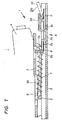
- Fig. 1 is a vertical longitudinal central section through an adjustment device provided on a heel holder, which is in the locked state
- Fig. 2 is a part of an analog section through the adjustment device in the unlocked state
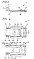
- the mudguard is shown in side view and in plan view
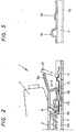
- Fig. 5 shows a detail of the fender on a larger scale in section along the line VV in Fig. 4.
- Figs. 4a, 6 and 7 a second embodiment of a heel holder according to the invention is shown.
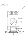
- Fig. 6 is a view of the same in the direction of arrow VI in Fig. 7, and Fig. 7 shows on a larger scale a partial section through the heel holder in the driving position, which partial section is taken through the vertical longitudinal median plane.
- 4a is a section similar to FIG. 4.
- the device shown in FIGS. 1 and 2 for the longitudinal adjustment of heel holders or the like is designated by 1 in its entirety. It consists of a guide rail 2 to be fastened to the ski, which is provided with two lateral guide strips and a recess extending centrally to its vertical longitudinal center plane. The latter is delimited on both sides by toothed bars 2a.
- a guide plate 3 is guided on the guide rail 2, on which a heel holder 4 is fastened.
- a web 5 is formed from the guide plate 3 and serves to support the transverse part of a guide element 6, which is U-shaped in plan view, for two helical compression springs 7.
- the guide plate 3 carries on its underside two lugs 8, which are intended to rest one leg 9a of the approximately U-shaped locking member 9.
- the leg 9a of the locking member 9 is plate-shaped and is penetrated by the ends of the legs 6a of the guide element 6 with play, so that it is pressed against the lugs 8 under the influence of the two helical compression springs 7, but against the guide element 6 within one certain area can pivot.
- a displacement of the legs 6a of the guide element 6 relative to the legs 9a is quite possible due to the game mentioned.
- the web 9b of the locking member 9 carries teeth which are intended for engagement in the toothed strips 2a of the guide rail 2.
- the leg 9c of the latching member 9 opposite the leg 9a is provided with an outwardly directed extension 9d which is used to raise the end of the latching member 9 by means of a screwdriver 10.
- a mudguard 11 which is intended to protect the two toothed strips 2a of the guide rail 2 against damage from the screwdriver 10 and therefore covers the toothed strips 2a in this area.
- the mudguard 11 has a rectangular recess 11c in its central region, which serves for the passage of the web 9b of the locking member 9 in the locked position thereof.
- the mudguard 11 has two bends 11a in one end region of its two long sides, in which elongated holes 11b b are left out (see FIG. 3). In these elongated holes 11b, horizontally arranged, transverse axles 9e engage, which project laterally from the locking member 9.
- the mudguard 11 carries two transverse ribs 11e and 11f, between which the end of the blade of the screwdriver 10 can be attached, as can be seen from FIGS. 1 and 2.
- the mudguard 11 which is approximately U-shaped in cross section, has two flanges 11g, which adjoin the ends of the two legs 11d and project with them, with which it rests on the regions of the guide rail 2 which adjoin the two toothed strips 2a in the transverse direction.
- the fender 11 is guided and stiffened by these flanges 11g, so that even with a very rough treatment of the adjusting device during the adjustment process, the mudguard 11 cannot bulge.
- the locking member 9 In the driving position of the heel holder 4, the locking member 9 is in the position shown in FIG. 1, in which it is pressed into the toothed strips 2a of the guide rail 2 by the two helical compression springs 7 with its web 9b supporting the teeth.
- the screwdriver 10 is inserted between the two ribs 11e and 11f and pivoted counterclockwise in the direction of the arrow 10a (see FIGS. 1 and 2).
- the locking member 9 is lifted out of the two toothed strips 2a, and the heel holder 4 can be adjusted along the guide rail 2.
- the two semiaxes 9e slide upwards along the two elongated holes 11b of the mudguard 11 until the locking member 9 has reached its upper position (see FIG. 2).
- the locking member 9 is pivoted back into the position shown in FIG. 1 under the influence of the two helical compression springs 7.
- the heel holder according to FIGS. 6 and 7 is designated in its entirety by 4 '. It is mounted on a guide rail 2 'which, in contrast to the guide rail 2 of the first exemplary embodiment, is provided with a row of holes 2'a.
- the heel holder 4 ' has a bearing block 20, in which a detent spring 22 is accommodated, which can be adjusted in its pretension by means of a screw 23, which acts on a spring plate 24.
- a locking member 19 is pivotally mounted at its left end in FIG. 7 in a manner not shown.
- the locking member 19 is acted upon by a spring 17, which strives to press the locking member into the locked position.
- the locking member 19 carries on its underside three locking teeth 19a, which are intended to engage in the holes in the row of holes 2'a.
- the end 19d of the locking member 19 protrudes beyond the rear boundary wall of the bearing block 20 and is used to engage a screwdriver with which the locking member 19 can be pivoted from the locked position into the unlocked position.
- a mudguard 21 which, in contrast to the mudguard 11 according to the first embodiment, as can be seen in connection with FIG Both legs 21c have bearing eyes 21a at their ends, in the elongated holes 21b of which semi-axes 19e engage, which are fastened to the locking member 19.
- the mudguard 21 also has two transverse ribs 21e and 21f on its section protruding beyond the rear boundary wall of the bearing bracket 20, which prevent the screwdriver from sliding off the mudguard.
- only the area of the perforated guide rail 2 ′ opposite the free end 19d of the locking member 19 is covered by the mudguard 21.
- the handling of the locking member 19 corresponds to that of the locking member 9, so that a more detailed explanation of the handling is unnecessary.
- the invention is by no means bound to the exemplary embodiments shown in the drawing and described above. Rather, various modifications of the same are conceivable without leaving the scope of the invention.
- the mudguard according to the invention can be used in versions in which the locking member can be locked in the pivoted-up position on the heel holder.
Description
Die Erfindung bezieht sich auf einen Fersenhalter gemäß dem ersten Teil des Patentanspruches 1.The invention relates to a heel holder according to the first part of
In der AT-B-374 692 ist eine Vorrichtung zur Längsverstellung von Skibindungsteilen mit einer am Ski zu befestigenden Führungsschiene beschrieben, die mit zwei seitlichen Führungsleisten und mit zwei zwischen diesen angeordneten, sich in der Längsrichtung der Vorrichtung erstreckenden Zahnleisten versehen ist, denen ein Rastglied zugeordnet, ist, das unter dem Einfluß von mindestens einer mit ihrem anderen Ende an einer auf der Führungsschiene geführten, den Fersenhalter tragenden Führungsplatte abgestützten Schraubendruckfeder steht und das - von der Seite gesehen - angenähert einen nach oben offenen U-förmigen Querschnitt besitzt, wobei der die beiden Schenkel verbindende Steg die Rastzähne trägt. Bei dieser Vorrichtung liegt der eine Schenkel des Rastgliedes unter dem Einfluß der Schraubendruckfeder an einem nach unten ragenden Ansatz der Führungsplatte an, und der andere Schenkel ist in der angehobenen Lage des Rastgliedes, wenn also die Rastzähne außer Eingriff mit den Zahnleisten sind, verrastbar.AT-B-374 692 describes a device for the longitudinal adjustment of ski binding parts with a guide rail to be fastened to the ski, which is provided with two lateral guide strips and with two toothed strips arranged between them and extending in the longitudinal direction of the device, to which a locking element is assigned, which is under the influence of at least one with its other end on a guided on the guide rail, the heel holder carrying guide plate supported helical compression spring and which - seen from the side - has an approximately open U-shaped cross-section, the the web connecting the two legs carries the locking teeth. In this device, one leg of the locking member bears under the influence of the helical compression spring on a downwardly projecting shoulder of the guide plate, and the other leg can be locked in the raised position of the locking member, that is to say when the locking teeth are out of engagement with the toothed strips.
Bei dieser Vorrichtung hat sich in der Praxis herausgestellt, daß das Verstellen des Fernsenhalters, das bei Leihski sehr häufig vorgenommen werden muß, nicht immer mit der erforderlichen Behutsamkeit erfolgt. Vielfach wird nämlich der zum Verstellen verwendete Schraubendreher so gewaltsam angesetzt und danach in einer Vertikalebene nach oben verschwenkt, daß es zu einer Beschädigung der empfindlichen Zähne der Zahnleisten kommt. Diese Beschädigungen können aber mitunter so groß werden, daß das Rastglied nur norch sehr schwer mit seinen Zähnen in die Zahnleisten einzusetzen ist bzw. daß die Zähne der Zahnleisten so deformiert werden, daß sie das Rastglied nicht mehr zuverlässig festhalten können, welches dann während der Abfahrt aus den Zahnleisten herausspringt.With this device it has been found in practice that the adjustment of the remote holder, which must be carried out very often with rental skis, is not always carried out with the necessary care. In many cases, the screwdriver used for adjustment is so forcefully attached and then pivoted upwards in a vertical plane that the sensitive teeth of the toothed strips are damaged. However, this damage can sometimes become so great that the locking member is only very difficult to insert with its teeth into the toothed racks or that the teeth of the toothed racks are deformed in such a way that they can no longer reliably hold the locking member, which then occurs during the descent pops out of the rack.
Es ist weiters vorgeschlagen worden, den Fersenhalter selbst mit einer Vorrichtung zu seiner Längsverstellung auszustatten (s. FR-A-2 451 756). Bei dieser Vorrichtung ist die Führungsschiene mit zwei Lochreihen versehen, in welche je zwei Vorsprünge eines Rastgliedes, das unter dem Einfluß einer Schraubenfeder gegen die Führungsschiene gedrückt wird, in der verrasteten Stellung der Vorrichtung einrasten. Das Rastglied ist bei nicht eingesetztem Skischuh an einer nach unten vorspringenden Wand des Gehäuses des Fersenhalters abgestützt. Es ist ständig mit einem etwa U-förmigen Drahtbügel gekuppelt, dessen in Querrichtung zur Führungsschiene verlaufender Steg in einer Ausnehmung des Fernsenhalters untergebracht ist.It has also been proposed to equip the heel holder itself with a device for its longitudinal adjustment (see FR-A-2 451 756). In this device, the guide rail is provided with two rows of holes, in each of which two projections of a locking member, which is pressed under the influence of a helical spring against the guide rail, engage in the locked position of the device. When the ski boot is not inserted, the latching element is supported on a wall of the housing of the heel holder that projects downward. It is constantly coupled with an approximately U-shaped wire bracket, the web of which runs in the transverse direction to the guide rail is accommodated in a recess in the remote holder.
Soll der Fersenhalter längs der Führungsschiene verstellt werden, so werden mittels eines Spezialwerkzeuges in Form eines Schraubendrehers mit zwei in den Schmalseitenflächen der Klinge angeordneten, gegen die Achse des Schraubendrehers hin gerichteten Nuten der Drahtbügel und damit das Rastglied angehoben, indem der Schraubendreher um 90° verschwenkt wird. Danach kann der Fersenhalter längs der Führungsschiene verschoben werden.If the heel holder is to be adjusted along the guide rail, a special tool in the form of a screwdriver with two grooves in the narrow side surfaces of the blade, directed towards the axis of the screwdriver, of the wire bracket and thus the locking element are raised by pivoting the screwdriver by 90 ° becomes. The heel holder can then be moved along the guide rail.
Ist die gewünschte Lage des Fersenhalters erreicht, so wird der Schraubendreher um 90° zurückgeschwenkt und danach aus dem Drahtbügel herausgezogen. Dadurch rasten infolge der Schraubenfeder die Vorsprünge des Rastgliedes in den Löchern der Führungsschiene ein. Diese Ausführungsform hat den Nachteil, daß zur Verstellung des Rastgliedes ein besonders ausgebildetes Werkzeug verwendet werden muß. Des weiteren muß während des Verstellvorganges das Werkzeug mit dem Bindungsteil in Eingriff bleiben, wodurch die eine Hand des Monteurs zu diesem Zweck in Anspruch genommen wird und für andere Einstellarbeiten nur die andere Hand des Monteurs zur Verfügung steht.When the desired position of the heel holder is reached, the screwdriver is swiveled back by 90 ° and then pulled out of the wire bracket. As a result, the projections of the locking member snap into the holes in the guide rail as a result of the helical spring. This embodiment has the disadvantage that a specially designed tool must be used to adjust the locking member. Furthermore, the tool must remain in engagement with the binding part during the adjustment process, whereby one hand of the fitter is used for this purpose and only the other hand of the fitter is available for other adjustment work.
Die Erfindung stellt sich die Aufgabe, einen Fersenhalter der eingangs genannten Art zu schaffen, bei dem auch nach längerem Gebrauch und bei wiederholter Verstellung keine Beschädigung der Zahnleisten der Führungsschiene stattfinden kann, wobei für den Verstellvorgang selbst nur ein handelsüblicher Schraubendreher erforderlich ist.The invention has for its object to provide a heel holder of the type mentioned, in which no damage to the toothed strips of the guide rail can take place even after prolonged use and repeated adjustment, wherein only a commercially available screwdriver is required for the adjustment process itself.
Dieses Aufgabe wird erfindungsgemäß durch die Merkmale des zweiten Teiles des Anspruches 1 gelöst. Dadurch kann der genannte Abschnitt auch bei rauher Behandlung durch den angesetzten Schraubendreher nicht beschädigt werden.This object is achieved by the features of the second part of
Durch die Maßnahme des Anspruches 2 wird eine satte Auflage des Schutzbleches auf der Führungs - schiene gewährleistet und eine Verbiegung desselben auch bei hochgeschwenktem Rastglied durch den Schraubendreher verhindert. Dabei hat sich der im Anspruch 3 angegebene Winkelbereich als besonders vorteilhaft erwiesen.The measure of
Der Gegenstand des Anspruches 4 bringt den Vorteil mit sich, daß eine gewisse Einsparung am Gewicht des Fersenhalters erzielt wird.The subject of
Das Merkmal des Anspruches 5-verhindert ein Abgleiten des Schraubendrehers vom Schutzblech in Richtung zu den Zähnen hin.The feature of
Schließlich erleichtert die Maßnahme des Anspruches 6 den Ansatz des Schraubendrehers am Schutzblech und verhindert gleichzeitig sein Abgleiten nach rückwärts.Finally, the measure of
In der Zeichnung sind zwei beispielsweise Ausführungsformen des Erfindungsgegenstandes rein schematisch dargestellt. Fig. 1 ist ein vertikaler Längsmittelschnitt durch eine an einem Fersenhalter vorgesehene Verstellvorrichtung, die sich im verrasteten Zustand befindet, und Fig. 2 ein Teil eines analogen Schnittes durch die Verstellvorrichtung im entrasteten Zustand. In den Fig. 3 und 4 ist das Schutzblech in Seitenansicht und in Draufsicht wiedergegeben. Fig. 5 zeigt ein Detail des Schutzbleches in größerem Maßstab im Schnitt nach der Linie V-V in Fig. 4. In den Fig. 4a, 6 und 7 ist eine zweite Ausführungsform eines erfindungsgemäßen Fersenhalters dargestellt. Fig. 6 ist eine Ansicht desselben in Richtung des Pfeiles VI in Fig. 7, und Fig. 7 zeigt in größerem Maßstab einen Teilschnitt durch den in Fahrtstellung befindlichen Fersenhalter, welcher Teilschnitt durch die vertikale Längsmittelebene gelegt ist. Fig. 4a ist ein Schnitt ähnlich der Fig. 4.In the drawing, two exemplary embodiments of the subject matter of the invention are shown purely schematically. Fig. 1 is a vertical longitudinal central section through an adjustment device provided on a heel holder, which is in the locked state, and Fig. 2 is a part of an analog section through the adjustment device in the unlocked state. 3 and 4, the mudguard is shown in side view and in plan view. Fig. 5 shows a detail of the fender on a larger scale in section along the line VV in Fig. 4. In Figs. 4a, 6 and 7, a second embodiment of a heel holder according to the invention is shown. Fig. 6 is a view of the same in the direction of arrow VI in Fig. 7, and Fig. 7 shows on a larger scale a partial section through the heel holder in the driving position, which partial section is taken through the vertical longitudinal median plane. 4a is a section similar to FIG. 4.
Die in den Fig. 1 und 2 dargestellte Vorrichtung zur Längsverstellung von Fersenhaltern od. dgl. ist in ihrer Gesamtheit mit 1 bezeichnet. Sie besteht aus einer am Ski zu befestigenden Führungsschiene 2, die mit zwei seitlichen Führungsleisten und einer mittig zu ihrer vertikalen Längsmittelebene sich erstreckenden Ausnehmung versehen ist. Letztere ist auf beiden Seiten von Zahnleisten 2a begrenzt.The device shown in FIGS. 1 and 2 for the longitudinal adjustment of heel holders or the like is designated by 1 in its entirety. It consists of a
Auf der Führungsschiene 2 ist eine Führungsplatte 3 geführt, auf der ein Fersenhalter 4 befestigt ist. Aus der Führungsplatte 3 ist ein Steg 5 ausgeprägt, welcher zur Auflage des Querteiles eines in Draufsicht U-förmigen Führungselementes 6 für zwei Schraubendruckfedern 7 dient. Weiters trägt die Führungsplatte 3 an ihrer Unterseite zwei Ansätze 8, die zur Anlage des einen Schenkels 9a des etwa U-förmigen Rastgliedes 9 bestimmt sind. Der Schenkel 9a des Rastgliedes 9 ist plattenförmig ausgebildet und wird von den Enden der Schenkel 6a des Führungselementes 6 mit Spiel durchsetzt, so daß er unter dem Einfluß der beiden Schraubendruckfedern 7 zwar an die Ansätze 8 angedrückt wird, sich jedoch gegenüber dem Führungselement 6 innerhalb eines gewissen Bereiches verschwenken kann. Weiters ist infolge des genannten Spieles eine Verschiebung der Schenkel 6a des Führungselementes 6 gegenüber dem Schenkel 9a durchaus möglich.A
Der Steg 9b des Rastgliedes 9 trägt Zähne, die zum Eingriff in die Zahnleisten 2a der Führungsschiene 2 bestimmt sind. Der dem Schenkel 9a gegenüberliegende Schenkel 9c des Rastgliedes 9 hingegen ist mit einem nach außen gerichteten Fortsatz 9d versehen, der zum Anheben des Endes des Rastgliedes 9 durch einen Schraubendreher 10 dient.The
Unterhalb des Rastgliedes 9 befindet sich ein Schutzblech 11, welches die beiden Zahnleisten 2a der Führungsschiene 2 gegen Beschädigungen durch den Schraubendreher 10 schützen soll und die Zahnleisten 2a daher in diesem Bereich abdeckt. Das Schutzblech 11 besitzt in seinem mittleren Bereich eine rechteckige Ausnehmung 11c, welche zum Durchtritt des Steges 9b des Rastgliedes 9 in der verrasteten Stellung desselben dient. Das Schutzblech 11 besitzt im einen Endbereich seiner beiden Längsseiten zwei Aufbiegungen 11a, in denen Langlöcher 11b b ausgespart sind (s. Fig. 3). In diese Langlöcher 11b greifen horizontal angeordnete, in Querrichtung verlaufende Halbachsen 9e ein, welche von dem Rastglied 9 seitlich vorragen.Below the
An dem der Anlenkstelle gegenüberliegenden Ende trägt das Schutzblech 11 zwei quer verlaufende, als Ausbuchtungen ausgebildete Rippen 11e und 11f, zwischen denen das Ende der Klinge des Schraubendrehers 10 angesetzt werden kann, wie aus den Fig. 1 und 2 hervorgeht. Schließlich besitzt das im Querschnitt etwa U-förmige Schutzblech 11 zwei an die Enden der beiden Schenkel 11d anschließende, nach außen ragende Flansche 11g, mit denen es auf den an die beiden Zahnleisten 2a in Querrichtung anschliessenden Bereichen der Führungsschiene 2 aufliegt. Durch diese Flansche 11g wird das Schutzblech 11 geführt und versteift, so daß auch bei einer sehr rauhen Behandlung der Verstellvorrichtung während des Verstellvorganges kein Verbeulen des Schutzbleches 11 eintreten kann.At the end opposite the articulation point, the
In der Fahrtstellung des Fersenhalters 4 befindet sich das Rastglied 9 in der in Fig. 1 dargestellten Lage, in der es durch die beiden Schraubendruckfedern 7 mit seinem die Zähne tragenden Steg 9b in die Zahnleisten 2a der Führungsschiene 2 gedrückt wird.In the driving position of the
Soll nun der Fersenhalter 4 in Skilängsrichtung verstellt werden, so wird der Schraubendreher 10 zwischen die beiden Rippen 11e und 11f eingeführt und in Richtung des Pfeiles 10a entegegen dem Uhrzeigersinn verschwenkt (vgl. die Fig. 1 und 2). Dadurch wird das Rastglied 9 aus den beiden Zahnleisten 2a herausgehoben, und der Fersenhalter 4 kann längs der Führungsschiene 2 verstellt werden. Dabei gleiten die beiden Halbachsen 9e entlang der beiden Langlöcher 11b des Schutzbleches 11 nach oben, bis das Rastglied 9 seine obere Lage erreicht hat (s. Fig. 2). Sobald jedoch der Schraubendreher 10 vom Fersenhalter 4 entfernt wird, wird das Rastglied 9 unter dem Einfluß der beiden Schraubendruckfedern 7 wieder in die in Fig. 1 dargestellte Lage geschwenkt.If the
Der Fersenhalter gemäß den Fig. 6 und 7 ist in seiner Gesamtheit mit 4' bezeichnet. Er ist auf einer Führungsschiene 2' gelagert, die im Gegensatz zur Führungsschiene 2 des ersten Ausführungsbeispieles mit einer Lochreihe 2'a versehen ist. Der Fersenhalter 4' besitzt einen Lagerbock 20, in dem eine Rastfeder 22 untergebracht ist, welche mittels einer Schraube 23, die auf einen Federteller 24 wirkt, in ihrer Vorspannung eingestellt werden kann.The heel holder according to FIGS. 6 and 7 is designated in its entirety by 4 '. It is mounted on a guide rail 2 'which, in contrast to the
Im unteren Bereich des Fersenhalters 4' ist ein Rastglied 19 an seinem in Fig. 7 linken Ende in nicht dargestellter Weise schwenkbar gelagert. Das Rastglied 19 wird von einer Feder 17 beaufschlagt, welche bestrebt ist, das Rastglied in die verrastete Lage zu drücken. Das Rastglied 19 trägt an seiner Unterseite drei Rastzähne 19a, die zum Eingriff in die Löcher der Lochreihe 2'a bestimmt sind. Das Ende 19d des Rastgliedes 19 ragt über die hintere Begrenzungswand des lagerbockes 20 hinaus und dient zum Angriff eines Schraubendrehers, mit dem das Rastglied 19 aus der verrasteten Lage in die nichtverrastete Lage verschwenkt werden kann.In the lower area of the heel holder 4 ', a
Unterhalb des Rastgliedes 19 befindet sich ein Schutzblech 21, das im Gegensatz zum Schutzblech 11 gemäß der ersten Ausführung, wie in Verbindung mit Fig. 4a erkennbar ist, in Darufsicht U-förmig ist, wobei der Steg den Abdeckbereich des Schutzbleches bildet und wobei die bieden Schenkel 21c an ihren Enden Lageraugen 21a tragen, in deren Langlöcher 21 b Halbachsen 19e eingreifen, welche am Rastglied 19 befestigt sind. Selbstverständlich trägt auch das Schutzblech 21 an seinem über die hintere Begrenzungswand des Lagerbrockes 20 hinausragenden Abschnitt zwei in Querrichtung verlaufende Rippen 21e und 21f, welche ein Abgleiten des Schraubendrehers vom Schutzblech verhindern. Bei dieser Ausführung des Schutzbleches 21 ist also nur der dem freien Ende 19d des Rastgliedes 19 gegenüberliegende Bereich der gelochten Führungsschiene 2' vom Schutzblech 21 abgedeckt.Below the
Die Handhabung des Rastgliedes 19 entspricht der des Rastgliedes 9, so daß sich eine nähere Erläuterung der Handhabung erübrigt.The handling of the
Selbstverständlich ist die Erfindung keineswegs an die in der Zeichnung dargestellten und im vorstehenden beschriebenen Ausführungsbeispiele gebunden. Vielmehr sind verschiedene Abänderungen derselben denkbar, ohne den Rahmen der Erfindung zu verlassen. Beispielsweise soll es möglich sein, das Schutzblech nach dem zweiten Ausführungsbeispiel auch beim ersten Ausführungsbeispiel zu verwenden und umgekehrt. Ferner kann das erfindungsgemäße Schutzblech bei Ausführungen verwendet werden, bei denen das Rastglied in der hochgeschwenkten Lage am Fersenhalter verrastbar ist.Of course, the invention is by no means bound to the exemplary embodiments shown in the drawing and described above. Rather, various modifications of the same are conceivable without leaving the scope of the invention. For example, it should be possible to use the mudguard according to the second embodiment in the first embodiment and vice versa. Furthermore, the mudguard according to the invention can be used in versions in which the locking member can be locked in the pivoted-up position on the heel holder.
Claims (6)
Applications Claiming Priority (2)
| Application Number | Priority Date | Filing Date | Title |
|---|---|---|---|
| AT0027985A AT381456B (en) | 1985-02-01 | 1985-02-01 | HEEL REST, ESPECIALLY FOR RENTAL SKI |
| AT279/85 | 1985-02-01 |
Publications (3)
| Publication Number | Publication Date |
|---|---|
| EP0190608A2 EP0190608A2 (en) | 1986-08-13 |
| EP0190608A3 EP0190608A3 (en) | 1987-08-05 |
| EP0190608B1 true EP0190608B1 (en) | 1990-05-02 |
Family
ID=3486318
Family Applications (1)
| Application Number | Title | Priority Date | Filing Date |
|---|---|---|---|
| EP86100820A Expired - Lifetime EP0190608B1 (en) | 1985-02-01 | 1986-01-22 | Heel holding device |
Country Status (6)
| Country | Link |
|---|---|
| US (1) | US4690424A (en) |
| EP (1) | EP0190608B1 (en) |
| JP (2) | JPS61181478A (en) |
| CN (1) | CN86100094B (en) |
| AT (1) | AT381456B (en) |
| DE (1) | DE3670771D1 (en) |
Families Citing this family (11)
| Publication number | Priority date | Publication date | Assignee | Title |
|---|---|---|---|---|
| FR2614545B1 (en) * | 1987-04-30 | 1989-06-16 | Salomon Sa | SECURITY FIXING FOR SKI |
| FR2614540B1 (en) * | 1987-04-30 | 1989-06-09 | Salomon Sa | SKI BINDING ADJUSTMENT TOOL |
| FR2638654B1 (en) * | 1988-11-08 | 1991-02-08 | Salomon Sa | SECURITY FIXING FOR SKI |
| DE58904223D1 (en) * | 1989-04-25 | 1993-06-03 | Look Sa | SAFETY SKI BINDING. |
| FR2656226B1 (en) * | 1989-12-27 | 1992-04-24 | Salomon Sa | SECURITY FIXING FOR SKI. |
| AT395538B (en) * | 1990-10-12 | 1993-01-25 | Tyrolia Freizeitgeraete | DEVICE FOR ADJUSTING THE LENGTH OF HEEL HOLDERS |
| FR2684889B1 (en) * | 1991-12-13 | 1994-02-04 | Salomon Sa | INTERFACE PIECE FOR THE SLIDE OF A FIXING ELEMENT, ESPECIALLY ALPINE FIXING. |
| FR2899121B1 (en) * | 2006-03-29 | 2008-07-04 | Salomon Sa | BACKGROUND SKI SET AND DOWNHOLE SKI FIXING DEVICE |
| FR2912317B1 (en) * | 2007-02-13 | 2009-05-08 | Salomon Sa | ASSEMBLY COMPRISING A DEVICE FOR THE SOLIDARIZATION OF A PLATINUM. |
| NO20170891A1 (en) * | 2017-05-30 | 2018-09-03 | Rottefella As | Mounting mechanism for a locking member to be attached to a mounting plate on a cross-country ski |
| RU178628U1 (en) * | 2017-07-12 | 2018-04-13 | Станислав Викторович Мозговой | FASTENING FOR RUNNING SKIS WITH SIMPLIFIED INSTALLATION FOR SKI USING SCREWS |
Family Cites Families (6)
| Publication number | Priority date | Publication date | Assignee | Title |
|---|---|---|---|---|
| AT276180B (en) * | 1965-12-20 | 1969-11-10 | Smolka & Co Wiener Metall | Ski binding element |
| FR2451756A1 (en) * | 1979-03-19 | 1980-10-17 | Salomon & Fils F | Safety binding for ski - is adjusted by lever moving stirrup joined to bolt which engages in slide on ski |
| AT371348B (en) * | 1981-06-12 | 1983-06-27 | Tyrolia Freizeitgeraete | DEVICE FOR ADJUSTING THE LENGTH OF SKI BINDING PARTS |
| DE3214585C3 (en) * | 1982-04-20 | 1996-06-13 | Rohrmoser Alois Skifabrik | Ski binding |
| AT374692B (en) * | 1982-07-05 | 1984-05-25 | Tyrolia Freizeitgeraete | DEVICE FOR ADJUSTING THE LENGTH OF SKI BINDING PARTS |
| AT377701B (en) * | 1983-03-04 | 1985-04-25 | Tyrolia Freizeitgeraete | DEVICE FOR LENGTH ADJUSTMENT |
-
1985
- 1985-02-01 AT AT0027985A patent/AT381456B/en not_active IP Right Cessation
-
1986
- 1986-01-14 CN CN86100094A patent/CN86100094B/en not_active Expired
- 1986-01-22 DE DE8686100820T patent/DE3670771D1/en not_active Expired - Fee Related
- 1986-01-22 EP EP86100820A patent/EP0190608B1/en not_active Expired - Lifetime
- 1986-01-29 US US06/823,552 patent/US4690424A/en not_active Expired - Fee Related
- 1986-01-31 JP JP61018256A patent/JPS61181478A/en active Pending
-
1991
- 1991-08-19 JP JP1991065251U patent/JPH0630220Y2/en not_active Expired - Lifetime
Also Published As
| Publication number | Publication date |
|---|---|
| DE3670771D1 (en) | 1990-06-07 |
| JPH0630220Y2 (en) | 1994-08-17 |
| JPH0488979U (en) | 1992-08-03 |
| EP0190608A2 (en) | 1986-08-13 |
| CN86100094B (en) | 1988-05-18 |
| EP0190608A3 (en) | 1987-08-05 |
| CN86100094A (en) | 1986-10-22 |
| US4690424A (en) | 1987-09-01 |
| JPS61181478A (en) | 1986-08-14 |
| ATA27985A (en) | 1986-03-15 |
| AT381456B (en) | 1986-10-27 |
Similar Documents
| Publication | Publication Date | Title |
|---|---|---|
| EP0499809B1 (en) | Supporting chain for energy carriers | |
| DE2624429B2 (en) | Clamping means | |
| EP0190608B1 (en) | Heel holding device | |
| DE3020346C2 (en) | ||
| DE3448346C2 (en) | ||
| DE2830676C2 (en) | Ski holding device | |
| DE19603657B4 (en) | Safety accessories for vehicles | |
| DE2945330A1 (en) | CONNECTOR BETWEEN A WIPER BLADE HOLDER AND A WIPER ARM | |
| DE2514772C3 (en) | Safety ski bindings | |
| DE3151964A1 (en) | DEVICE FOR DETACHABLE FASTENING | |
| AT391274B (en) | SKI BINDING | |
| DE3717108C2 (en) | Safety ski binding as well as the whole consisting of skis and safety bindings | |
| DE2947121C2 (en) | Holding device for ski pairs | |
| EP0051051B1 (en) | A luggage carrier for vehicles | |
| DE19502681A1 (en) | Strain relief and fastener | |
| AT264178B (en) | Harrow beam | |
| EP0105055B1 (en) | Lorry for receiving a harvesting device | |
| DE19860213B4 (en) | trolley | |
| DE3021098A1 (en) | Work trolley with trays - has horizontal and two vertical frames with wheels, to support trays | |
| DE19623691C2 (en) | Holding device for vehicle accessories or vehicle accessories | |
| DE3014061C2 (en) | ||
| DE2729726C2 (en) | Handle attachment to a harness | |
| DE2611743A1 (en) | TOE FOR SAFETY SKI BINDINGS | |
| DE2816952C2 (en) | Articulated connection for the detachable storage of turning panels in support rails | |
| DE2630451C3 (en) |
Legal Events
| Date | Code | Title | Description |
|---|---|---|---|
| PUAI | Public reference made under article 153(3) epc to a published international application that has entered the european phase |
Free format text: ORIGINAL CODE: 0009012 |
|
| AK | Designated contracting states |
Kind code of ref document: A2 Designated state(s): CH DE FR LI |
|
| PUAL | Search report despatched |
Free format text: ORIGINAL CODE: 0009013 |
|
| AK | Designated contracting states |
Kind code of ref document: A3 Designated state(s): CH DE FR LI |
|
| 17P | Request for examination filed |
Effective date: 19870808 |
|
| 17Q | First examination report despatched |
Effective date: 19881207 |
|
| GRAA | (expected) grant |
Free format text: ORIGINAL CODE: 0009210 |
|
| AK | Designated contracting states |
Kind code of ref document: B1 Designated state(s): CH DE FR LI |
|
| REF | Corresponds to: |
Ref document number: 3670771 Country of ref document: DE Date of ref document: 19900607 |
|
| ET | Fr: translation filed | ||
| PLBE | No opposition filed within time limit |
Free format text: ORIGINAL CODE: 0009261 |
|
| STAA | Information on the status of an ep patent application or granted ep patent |
Free format text: STATUS: NO OPPOSITION FILED WITHIN TIME LIMIT |
|
| 26N | No opposition filed | ||
| REG | Reference to a national code |
Ref country code: CH Ref legal event code: PUE Owner name: AMF CORPORATION TRANSFER- HTM SPORTS CORP. Ref country code: CH Ref legal event code: PFA Free format text: TMC CORPORATION |
|
| REG | Reference to a national code |
Ref country code: FR Ref legal event code: TP Ref country code: FR Ref legal event code: CD |
|
| REG | Reference to a national code |
Ref country code: CH Ref legal event code: PFA Free format text: HTM SPORT- UND FREIZEITGERAETE AKTIENGESELLSCHAFT |
|
| REG | Reference to a national code |
Ref country code: FR Ref legal event code: TP |
|
| PGFP | Annual fee paid to national office [announced via postgrant information from national office to epo] |
Ref country code: FR Payment date: 19950104 Year of fee payment: 10 Ref country code: DE Payment date: 19950104 Year of fee payment: 10 |
|
| PGFP | Annual fee paid to national office [announced via postgrant information from national office to epo] |
Ref country code: CH Payment date: 19950127 Year of fee payment: 10 |
|
| PG25 | Lapsed in a contracting state [announced via postgrant information from national office to epo] |
Ref country code: LI Effective date: 19960131 Ref country code: CH Effective date: 19960131 |
|
| REG | Reference to a national code |
Ref country code: CH Ref legal event code: PL |
|
| PG25 | Lapsed in a contracting state [announced via postgrant information from national office to epo] |
Ref country code: FR Effective date: 19960930 |
|
| PG25 | Lapsed in a contracting state [announced via postgrant information from national office to epo] |
Ref country code: DE Effective date: 19961001 |
|
| REG | Reference to a national code |
Ref country code: FR Ref legal event code: ST |