EP0190573A2 - Device for separating documents - Google Patents
Device for separating documents Download PDFInfo
- Publication number
- EP0190573A2 EP0190573A2 EP86100460A EP86100460A EP0190573A2 EP 0190573 A2 EP0190573 A2 EP 0190573A2 EP 86100460 A EP86100460 A EP 86100460A EP 86100460 A EP86100460 A EP 86100460A EP 0190573 A2 EP0190573 A2 EP 0190573A2
- Authority
- EP
- European Patent Office
- Prior art keywords
- document
- transport
- roller
- boundary wall
- recording medium
- Prior art date
- Legal status (The legal status is an assumption and is not a legal conclusion. Google has not performed a legal analysis and makes no representation as to the accuracy of the status listed.)
- Granted
Links
- 239000000969 carrier Substances 0.000 claims abstract description 8
- 238000000926 separation method Methods 0.000 claims abstract description 6
- 230000032258 transport Effects 0.000 description 46
- 230000004888 barrier function Effects 0.000 description 2
- 239000000463 material Substances 0.000 description 2
- 230000005540 biological transmission Effects 0.000 description 1
- 230000007423 decrease Effects 0.000 description 1
- 230000002349 favourable effect Effects 0.000 description 1
- 238000000034 method Methods 0.000 description 1
Images
Classifications
-
- B—PERFORMING OPERATIONS; TRANSPORTING
- B65—CONVEYING; PACKING; STORING; HANDLING THIN OR FILAMENTARY MATERIAL
- B65H—HANDLING THIN OR FILAMENTARY MATERIAL, e.g. SHEETS, WEBS, CABLES
- B65H3/00—Separating articles from piles
- B65H3/46—Supplementary devices or measures to assist separation or prevent double feed
-
- B—PERFORMING OPERATIONS; TRANSPORTING
- B65—CONVEYING; PACKING; STORING; HANDLING THIN OR FILAMENTARY MATERIAL
- B65H—HANDLING THIN OR FILAMENTARY MATERIAL, e.g. SHEETS, WEBS, CABLES
- B65H2701/00—Handled material; Storage means
- B65H2701/10—Handled articles or webs
- B65H2701/19—Specific article or web
- B65H2701/1912—Banknotes, bills and cheques or the like
Definitions
- the invention relates to a device for separating record carriers which are removed from a storage container and fed to a transport route. Separation problems occur with the most varied types of record carriers, for example with banknotes, but in particular also with documents for document processing in the banking business.
- a separating device in which the recording media, in this case banknotes, are passed between two counter-rotating transport rollers, one conveyor roller driving in the direction of transport, while the second counter-rotating transport roller one holds back the second, possibly erroneously supplied, document due to its opposite drive movement.
- the known device is based on the principle that the friction between the first transport roller, which is provided with a corresponding friction lining, and the surface of the recording medium is greater than the friction between the recording medium, which is smooth per se.
- the invention is based on a device for separating record carriers, which are removed from a storage container and fed to a transport path, the record carriers passing between two counter-rotating transport rollers, the first of which moves the record carrier in the desired transport direction, while the second moves a second Retains record carrier due to the different friction conditions, and is characterized in that the second transport roller is pivotally mounted by a small amount such that the width of the passage slot between the two transport rollers automatically different adapts to strong types of record carriers.
- the second transport roller is mounted on a swivel lever which can be swiveled between adjustable stops.
- an easily rotatable sensor roller is provided, which cooperates with the back of the recording medium and the passage slot keeps open during the passage of the recording medium.
- the sensing roller is preferably held tangentially and adjustable in the circumferential direction on the axis of the second transport roller.
- the document storage container in addition to the normal, movable rear wall, also has a movable lower boundary wall and that a very long tension spring acts on the movable parts, which exerts an almost constant pressure regardless of the height of the document stack.
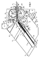
- a document storage container 2 is arranged on a holding plate 1.
- the document storage container 2 consists of a front boundary wall 3 and a displaceable, rear boundary wall 4.
- the boundary wall 4 is connected to a displaceable part, which represents the lower boundary wall 5, which is displaceably mounted on a sliding guide 6 with guide means.
- the part 4/5 is under the influence of a long tension spring 7, ' which is deflected around a roller 8 and is attached to a pin 9.
- the lower boundary wall 5 is displaced on the sliding guide 6 between two fixed boundary surfaces 10 and 11 which, in addition to the displaceable part 6, form the bottom of the document storage compartment 2.
- the part 5 transfers somewhat the level of the parts 10 and 11, so that the documents 20 of the document stack 13 only stand on the part 5.
- the rear boundary wall 4 is guided so obliquely between the parts 10 and 11 that it rests against the document stack 13 only with its right front end 12.
- a tongue of the rear boundary wall 4 is also provided with a friction lining 14 which rests on the rearmost document.
- a take-off roller 15 provided with a friction lining is mounted on an axis 16 and ensures that the foremost document 20 is always pushed out and inserted between the two boundary walls 3 and 17.
- a lateral guide part .18 is angled to the inlet opening between the guide parts 3 and 17 so that a funnel-shaped inlet opening 19 is formed.
- a limit switch 22 with a sensing arm 21 serves to completely interrupt the document transport when the document stack 13 has been processed.
- the one just described and in the F IG. 1 shown form of training the document storage container 2 has the advantage that already when introducing the documents in the document transport line precaution is taken to ensure that the documents are kept clean as the stack of documents decreases because they stand up on a movable lower boundary wall and that on the other hand the pressure on the stack of documents regardless of its size is relatively constant, so that the pre-separation by the take-off roller 15 already ensures that not too many documents are transported at the same time.
- the separating station 24 now comprises the two transport rollers 25 and 26, which are mounted on the axes 27 and 28.
- the transport roller 25 is the first transport role shown in FIG. 1 runs clockwise and which transports the document in the transport direction.
- the transport roller 26, on the other hand, is the second transport roller that is driven against the transport direction and thus has the task of pushing back the second document, which may be fed behind the foremost document 20.
- Both transport rollers 25 and 26 are provided with a corresponding friction lining.
- the second transport roller 26 and the take-off roller 15 are coated with the material Linatex. This material has proven to be particularly favorable in terms of its coefficient of friction and low wear.
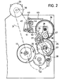
- the separating device 24 and in particular its drive elements can be seen in detail from FIG. 2.
- the motor 29 drives a belt wheel 32 via a belt wheel 30 and a belt 31.
- a gear 34 is connected to the belt wheel 32 via an axis 33.
- the gear 34 engages on the one hand with the gear 35 which is mounted on the shaft 16 and drives the pull-off roller 15, on the other hand with a gear 36 which is mounted on the shaft 27 and connected to the transport roller 25.
- the gear 36 in turn drives an intermediate gear 37 which is mounted and held on a lever 38.
- the intermediate gear 37 in turn is in engagement with the gear 39, which is arranged on the shaft 28 and connected to the transport gear 26.
- the shaft 28 is attached to a pivot lever 40.
- the pivot lever 40 is rotatable about the pin 41 and has an arm 42 on which a tension spring 43 acts.
- the lever 40 can pivot about its pivot point 41 between two adjustable stops 44 and 45.
- the pivoting is so much that at most the strongest documents can pass between the two transport rollers 25 and 26.
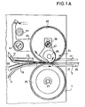
- the stop 44 is eccentric so that the basic position of the transport roller 26 can be adjusted so that the thinnest document between the two rolls 25 and 26 can happen. From FIG. 1A it can be seen that a document 20 runs between the two transport rollers 25 and 26, while the other, rear document 20 is pushed back by the transport roller 26, which runs counterclockwise, or at least is prevented from passing until the document lying in front of it is not 20 has cleared the way.
- an additional sensing roller 46 is provided, which is rotatably mounted on a holding part 47.
- the holding part 47 is fastened on the axis 28 by means of a longitudinal slot and a corresponding screw, so that it is possible to adjust the circumferential position of the sensing roller 46 and the tangential position of this roller.
- the setting is such that the sensing roller with its outermost point is offset by approximately 1 ° to 2 ° compared to the point at which the two transport rollers 25 and 26 are closest to one another, ie at which the document is gripped and transported.
- the roller 46 protrudes a very small amount beyond the circumference of the transport roller 26. So is the transport roller 26 by a stronger document 20 in FIG. 1 and 1A is pivoted counterclockwise by a small amount, then the document comes after a short further transport to the sensing roller 46 and thereby causes a slight further pivoting of the conveying roller 26.
- the F yerrolle 46 rolls while on the back side of the transported document, while the transport roller 26 is relieved. The transport of the document is facilitated in this way, the sensing roller 46 cooperating with a bulge 50 of the boundary wall 3.
Landscapes
- Engineering & Computer Science (AREA)
- Mechanical Engineering (AREA)
- Sheets, Magazines, And Separation Thereof (AREA)
- Conveying Record Carriers (AREA)
- Detergent Compositions (AREA)
- Dental Preparations (AREA)
- Photoreceptors In Electrophotography (AREA)
Abstract
Die Erfindung bezieht sich auf eine Einrichtung zur Belegvereinzelung. Die Aufzeichnungsträger (20) werden zwischen zwei Transportrollen (25, 26) bewegt, von denen die eine den Beleg in Vorwärtsrichtung antreibt, während die andere gegenläufig angetrieben wird und einen etwa zugeführten zweiten Beleg (20) zurückhält. Unterschiedliche Belegstärken können dadurch verarbeitet werden, daß die gegenläufig angetriebene Transportrolle (26) um einen kleinen Betrag verschwenkbar angeordnet ist, so daß sich der Durchtrittsschlitz für die Belege (20) automatisch der gerade zugerführten Belegstärke anpaßt. Eine Fühlrolle (46) hält den Durchtrittschlitz offen. Der Belegvorratsbehälter (2) hat eine verschiebliche, rückwärtige und untere Begrenzungswand (4, 5), die unter dem Zug einer langen Zugfeder (7) steht, um einen relativ gleichbleibenden Druck an der Abzugsrolle (15) zu erreichen.The invention relates to a device for document separation. The record carriers (20) are moved between two transport rollers (25, 26), one of which drives the document in the forward direction, while the other is driven in opposite directions and retains an approximately supplied second document (20). Different document thicknesses can be processed in that the oppositely driven transport roller (26) is pivotable by a small amount, so that the passage slot for the documents (20) automatically adapts to the document thickness just fed. A feeler roller (46) keeps the passage slot open. The document storage container (2) has a displaceable, rear and lower boundary wall (4, 5) which is under the tension of a long tension spring (7) in order to achieve a relatively constant pressure on the take-off roller (15).
Description
Die Erfindung bezieht sich auf eine Einrichtung zur Vereinzelung von Aufzeichnungsträgern, die aus einem Vorratsbehälter entnommen und einer Transportstrecke zugeführt werden. Vereinzelungsprobleme treten bei den verschiedensten Arten von Aufzeichnungsträgern auf, beispielsweise bei Banknoten, insbesondere aber auch bei Belegen für die Belegverarbeitung im Bankgeschäft.The invention relates to a device for separating record carriers which are removed from a storage container and fed to a transport route. Separation problems occur with the most varied types of record carriers, for example with banknotes, but in particular also with documents for document processing in the banking business.
Aus der DE-AS 26 50 564 ist beispielsweise eine Vereinzelungsvorrichtung bekannt, bei der die Aufzeichnungsträger, in diesem Falle Banknoten, zwischen zwei gegenläufig angetriebenen Transportrollen hindurchgeführt werden, wobei eine Transportrolle den Antrieb in Transportrichtung bewirkt, während die zweite, gegenläufig angetriebene Transportrolle, einen zweiten, etwa irrtümlich zugeführten Beleg durch ihre gegenläufige Antriebsbewegung zurückhält. Die bekannte Einrichtung beruht auf dem Prinzip, daß die Reibung zwischen der ersten Transportrolle, die mit einem entsprechenden Reibbelag versehen ist, und der Oberfläche des Aufzeichnungsträgers größer ist als die Reibung der an sich glatten Aufzeichnungsträger untereinander.From DE-AS 26 50 564, for example, a separating device is known in which the recording media, in this case banknotes, are passed between two counter-rotating transport rollers, one conveyor roller driving in the direction of transport, while the second counter-rotating transport roller one holds back the second, possibly erroneously supplied, document due to its opposite drive movement. The known device is based on the principle that the friction between the first transport roller, which is provided with a corresponding friction lining, and the surface of the recording medium is greater than the friction between the recording medium, which is smooth per se.
Bei der bekannten Anordnung muß zwischen den beiden gegenläufig angetriebenen Transportrollen ein genau definierter Abstand vorhanden sein, der praktisch der Dicke eines Aufzeichnungsträgers entspricht. Damit ist der Durchtrittsschlitz für die Aufzeichnungsträger zwischen den beiden Transportrollen definiert.In the known arrangement there must be a precisely defined distance between the two counter-rotating transport rollers, which practically corresponds to the thickness of a record carrier. This defines the passage slot for the record carriers between the two transport rollers.
Bei der Verarbeitung von Belegen stellt sich jedoch das Problem, daß unterschiedliche Belegarten, insbesondere unterschiedlich starke Belege, verarbeitet werden sollen. Beispielsweise bestehen einige Belege, wie z. B. Schecks, nur aus einem einzigen Blatt Papier, während andere Belegarten, wie beispielsweise Überweisungsformulare, Dreifachbelegsätze sind, die über einen perforierten Randstreifen, aber zu einem Beleg miteinander verbunden sind. Es versteht sich von selbst, daß derartige Dreifachbelegsätze viel stärker sind als ein einfacher Scheck. Noch schwieriger ist es, wenn beispielsweise ein Beleg als nicht lesbar erkannt wird und deswegen mit einer Hülle versehen wird, durch die der Beleg dann der weiteren Belegverarbeitung zugeführt wird. Diese Hülle umgibt den Beleg und ist selbstverständlich noch stärker als die bereits erwähnten Dreifachbelege.When processing documents, however, the problem arises that different types of documents, especially un documents of varying strength to be processed. For example, there is some evidence, such as B. Checks, only from a single sheet of paper, while other types of receipts, such as transfer forms, are triple receipts, which are connected to each other via a perforated edge strip, but to form a receipt. It goes without saying that such triple document sets are much stronger than a simple S check. It is even more difficult if, for example, a document is recognized as illegible and is therefore provided with a cover through which the document is then passed on for further document processing. This envelope surrounds the document and is of course even stronger than the triple documents already mentioned.
Bisher war es üblich, die unterschiedlich starken Belegsorten vorzusortieren und immer nur eine Belegart zu verarbeiten, wobei zwischen je zwei Belegarten eine Einstellung des Durchtrittsschlitzes für die Belegarten erfolgte. Demgegenüber ist es jetzt das Ziel der Erfindung zu erreichen, daß die unterschiedlich starken Belegarten untereinander vermischt verarbeitet werden können, ohne daß es zwischenzeitlich irgendwelcher Einstellarbeiten an der Verarbeitungseinheit bedarf.Previously, it was customary to pre-sort the document types of different strengths and to process only one document type at a time, whereby the passage slot for the document types was set between two document types. In contrast, it is now the aim of the invention to achieve that the differently strong document types can be processed mixed with each other without the need for any adjustment work on the processing unit in the meantime.
Die Erfindung geht aus von einer Einrichtung zur Vereinzelung von Aufzeichnungsträgern, die aus einem Vorratsbehälter entnommen und einer Transportstrecke zugeführt werden, wobei die Aufzeichnungsträger zwischen zwei gegenläufig angetriebenen Transportrollen passieren, von denen die erste den Aufzeichnungsträger in der gewünschten Transportrichtung bewegt, während die zweite einen zweiten Aufzeichnungsträger aufgrund der unterschiedlichen Reibungsverhältnisse zurückhält, und ist dadurch gekennzeichnet, daß die zweite Transportrolle um ein geringes Maß derart schwenkbar gelagert ist, daß sich die Weite des Durchtrittsschlitzes zwischen den beiden Transportrollen automatisch den unterschiedlich starken Aufzeichnungsträgerarten anpaßt.The invention is based on a device for separating record carriers, which are removed from a storage container and fed to a transport path, the record carriers passing between two counter-rotating transport rollers, the first of which moves the record carrier in the desired transport direction, while the second moves a second Retains record carrier due to the different friction conditions, and is characterized in that the second transport roller is pivotally mounted by a small amount such that the width of the passage slot between the two transport rollers automatically different adapts to strong types of record carriers.
Gemäß der weiteren Erfindung ist die zweite Transportrolle auf einem Schwenkhebel gelagert, der zwischen einstellbaren Anschlägen schwenkbar ist.According to the further invention, the second transport roller is mounted on a swivel lever which can be swiveled between adjustable stops.
Um den Transport des vereinzelten Beleges entgegen der Reibungskraft der zweiten Transportrolle zu erleichtern, ist in Transportrichtung gesehen unmittelbar hinter der Berührungsstelle zwischen der ersten und der zweiten Transportrolle mit dem Beleg eine leicht drehbar gelagerte Fühlrolle vorgesehen, die mit der Rückseite des Aufzeichnungsträgers zusammenwirkt und den Durchtrittsschlitz während des Vorbeilaufes des Aufzeichnungsträgers offenhält. Vorzugsweise ist die Fühlrolle tangential und in Umfangsrichtung einstellbar auf der Achse der zweiten Transportrolle gehalten.In order to facilitate the transport of the separated document against the frictional force of the second transport roller, seen in the transport direction immediately behind the point of contact between the first and the second transport roller with the document, an easily rotatable sensor roller is provided, which cooperates with the back of the recording medium and the passage slot keeps open during the passage of the recording medium. The sensing roller is preferably held tangentially and adjustable in the circumferential direction on the axis of the second transport roller.
Gemäß der weiteren Erfindung hat es sich als notwendig erwiesen, bereits bei der Entnahme der Belege aus dem Vorratsbehälter dafür zu sorgen, daß eine gewisse Vereinzelung stattfindet. Diese ist insbesondere dann gegeben, wenn dafür Sorge getragen wird, daß die Belege immer mit nahezu gleichbleibendem Druck an die Abzugsrolle angedrückt werden und daß Reibungsverluste beim Nachführen des Belegstapels zu der Abzugsrolle weitestgehend vermieden werden.According to the further invention, it has been found necessary to ensure that a certain separation takes place as soon as the receipts are removed from the storage container. This is particularly the case if care is taken to ensure that the receipts are always pressed onto the take-off roller with almost constant pressure and that friction losses when the stack of receipts is brought up to the take-off roll are largely avoided.
Erreicht wird dies dadurch, daß der Belegvorratsbehälter außer der normalen, verschieblichen Rückwand auch eine verschiebliche untere Begrenzungswand hat und daß eine sehr lange Zugfeder auf die verschieblichen Teile einwirkt, die einen nahezu gleichbleibenden Andruck unabhängig von der Höhe des Belegstapels ausübt.This is achieved in that the document storage container, in addition to the normal, movable rear wall, also has a movable lower boundary wall and that a very long tension spring acts on the movable parts, which exerts an almost constant pressure regardless of the height of the document stack.
Weitere Einzelheiten der Erfindung ergeben sich anhand einer Beschreibung eines in den Zeichnungen gezeigten Ausführungsbeispieles der Erfindung. In den Zeichnungen ist
- FIG. 1 eine übersichtsdarstellung des Vorratsbehälters und der Vereinzelungsvorrichtung,
- FIG. 1A eine Vergrößerung eines Details der FIG. 1,
- FIG. 2 zeigt das Getriebe, welches dem Antrieb der Aufzeichnungsträger dient.
- FIG. 1 shows an overview of the storage container and the separating device,
- FIG. 1A is an enlargement of a detail of FIG. 1,
- FIG. 2 shows the transmission which serves to drive the recording media.
Auf einer Halteplatte 1 ist ein Belegvorratsbehälter 2 angeordnet. Der Belegvorratsbehälter 2 besteht aus einer vorderen Begrenzungswand 3 und einer verschiebbaren, hinteren Begrenzungswand 4. Die Begrenzungswand 4 ist mit einem verschiebbaren Teil verbunden, welches die untere Begrenzungswand 5 darstellt, die mit Führungsmitteln auf einer Gleitführung 6 verschiebbar gelagert ist. Hierfür steht das Teil 4/5 unter dem Einfluß einer langen Zugfeder 7,'die um eine Rolle 8 umgelenkt wird und an einem Zapfen 9 befestigt ist. Die untere Begrenzungswand 5 wird auf der Gleitführung 6 zwischen zwei feststehenden Begrenzungsflächen 10 und 11 verschoben, die im übrigen zusätzlich zu dem verschiebbaren Teil 6 den Boden des Belegvorratsfaches 2 bilden. Dabei überträgt das Teil 5 aber etwas die Ebene der Teile 10 und 11, so daß die Belege 20 des Belegstapels 13 nur auf dem Teil 5 aufstehen. Die hintere Begrenzungswand 4 ist derart schräg geführt zwischen den Teilen 10 und 11, daß sie nur mit ihrem rechten vorderen Ende 12 an dem Belegstapel 13 anliegt. Um eine gute Reibung zwischen den vorderen Belegen 20 einerseits und dem letzten Beleg sicherzustellen, ist eine Zunge der hinteren Begrenzungswand 4 noch mit einem Reibbelag 14 versehen, der auf dem hintersten Beleg aufliegt.A document storage container 2 is arranged on a
Eine mit einem Reibungsbelag versehene Abzugsrolle 15 ist auf einer Achse 16 gelagert und sorgt dafür, daß immer der vorderste Beleg 20 herausgeschoben wird und zwischen die beiden Begrenzungswände 3 und 17 eingeführt wird. Ein seitliches Führungsteil .18 ist zu der Einlauföffnung zwischen den Führungsteilen 3 und 17 so abgewinkelt, daß eine trichterförmige Einlauföffnung 19 entsteht. Ein Endabschalter 22 mit einem Fühlarm 21 dient dazu,den.Belegtransport vollkommen zu unterbrechen, wenn der Belegstapel 13 abgearbeitet ist.A take-
Die soeben geschilderte und in der FIG. 1 dargestellte Ausbildungsform des Belegvorratsbehälters 2 hat den Vorteil, daß bereits bei der Einführung der Belege in die Belegtransportstrecke Vorsorge dafür getroffen ist, daß die Belege bei abnehmendem Belegstapel sauber nachgeführt werden, weil sie .auf einer beweglichen unteren Begrenzungswand aufstehen und daß zum anderen der Druck auf den Belegstapel unabhängig von dessen Größe relativ gleichbleibend ist, so daß bei der Vorvereinzelung durch die Abzugsrolle 15 bereits sichergestellt wird, daß nicht zuviele Belege gleichzeitig transportiert werden.The one just described and in the F IG. 1 shown form of training the document storage container 2 has the advantage that already when introducing the documents in the document transport line precaution is taken to ensure that the documents are kept clean as the stack of documents decreases because they stand up on a movable lower boundary wall and that on the other hand the pressure on the stack of documents regardless of its size is relatively constant, so that the pre-separation by the take-
Zwischen den beiden Begrenzungswänden 3 und 17 passieren die Belege nun einen Reibbelag 23, der an der Begrenzungswand 17 befestigt ist und als Vorvereinzelung dient. Da-bei ist die Absicht die, zu erreichen, daß, wenn zwei Belege an der eigentlichen Vereinzelungsstation 24 ankommen, wenigstens Sorge dafür getragen werden soll, daß der eine Beleg, und zwar der vordere Beleg, ein wenig vor dem dahinter liegenden Beleg voreilt.Between the two
Die Vereinzelungsstation 24 umfaßt nun die beiden Transportrollen 25 und 26, die auf den Achsen 27 und 28 gelagert sind. Die Transportrolle 25 ist die erste Transportrolle, die in FIG. 1 im Uhrzeigersinne läuft und die den Beleg in Transportrichtung transportiert. Die Transportrolle 26 dagegen ist die zweite Transportrolle, die gegen die Transportrichtung angetrieben wird und damit die Aufgabe hat, den zweiten Beleg, der hinter dem vordersten Beleg 20 evtl. zugeführt wird, zurückzudrücken. Beide Transportrollen 25 und 26 sind mit einem entsprechenden Reibbelag versehen. Insbesondere die zweite Transportrolle 26 und die Abzugsrolle 15 sind mit dem Material Linatex belegt. Dieses Material hat sich hinsichtlich seines Reibwertes und des geringen Verschleißes als besonders günstig herausgestellt.The separating
Im einzelnen erkennt man die Vereinzelungsvorrichtung 24 und insbesondere ihre Antriebsorgane aus der FIG. 2. Der Motor 29 treibt über ein Riemenrad 30 und einen Riemen 31 ein Riemenrad 32 an. Mit dem Riemenrad 32 ist über eine Achse 33 ein Zahnrad 34 verbunden. Das Zahnrad 34 steht einerseits mit dem Zahnrad 35 in Eingriff, welches auf der Welle 16 gelagert ist, und die Abzugsrolle 15 antreibt, andererseits mit einem Zahnrad 36, welches auf der Welle 27 gelagert und mit der Transportrolle 25 verbunden ist. Das Zahnrad 36 seinerseits treibt ein Zwischenrad 37 an, welches auf einem Hebel 38 gelagert und gehalten ist. Das Zwischenrad 37 wiederum steht im Eingriff mit dem Zahnrad 39, welches auf der Welle 28 angeordnet ist und mit dem Transportrad 26 verbunden. Die Welle 28 ist auf einem Schwenkhebel 40 befestigt. Der Schwenkhebel 40 ist drehbar um den Zapfen 41 und besitzt einen Arm 42, auf den eine Zugfeder 43 einwirkt. Zwischen zwei einstellbaren Anschlägen 44 und 45 kann der Hebel 40 um seinen Schwenkpunkt 41 verschwenken. Die Verschwenkung beträgt soviel, daß maximal die stärksten Belege zwischen den beiden Transportrollen 25 und 26 passieren können. Man erkennt, daß der Anschlag 44 exzentrisch ist, so daß man die Grundstellung der Transportrolle 26 so einstellen kann, daß der dünnste Beleg zwischen den beiden Rollen 25 und 26 passieren kann. Aus der FIG. 1A erkennt man, daß ein Beleg 20 zwischen den beiden Transportrollen 25 und 26 hindurchläuft, während der andere, hintere Beleg 20 durch die Tranportrolle 26, die im Gegenuhrzeigersinne läuft, zurückgeschoben wird oder zumindesten solange am Passieren gehindert wird, bis nicht der davor liegende Beleg 20 den Weg freigegeben hat.The
Wegen des Antriebes der Transportrolle 26 im Gegenuhrzeigersinne läuft der Transport durch die Transportrolle 25 sehr schwer. Um dies etwas zu erleichtern, ist eine zusätzliche Fühlrolle 46 vorgesehen, die auf einem Halteteil 47 drehbar gelagert ist. Das Halteteil 47 ist mittels eines Längsschlitzes .und einer entsprechenden Schraube auf der Achse 28 befestigt, so daß es möglich ist, die Umfangsstellung der Fühlrolle 46 und die tangentiale Lage dieser Rolle einzustellen. Die Einstellung ist dabei eine derartige, daß die Fühlrolle mit ihrem äußersten Punkt um etwa 1° bis 2° versetzt ist gegenüber dem Punkt, an dem sich die beiden Transportrollen 25 und 26 am dichtesten gegenüberstehen, an dem also der Beleg ergriffen und transportiert wird. Außerdem ragt die Rolle 46 um ein ganz geringes Maß über den Umfang der Transportrolle 26 hinaus. Wird also die Transportrolle 26 durch ei nen stärkeren Beleg 20 in FIG. 1 und 1A im Gegenuhrzeigersinn um ein geringes Maß verschwenkt, dann stößt der Beleg schon nach einem kurzen weiteren Transportweg gegen die Fühlrolle 46 und bewirkt dadurch eine geringfügige weitere Verschwenkung der Transportrolle 26. Die Fühlrolle 46 rollt dabei auf der Rückseite des transportierten Beleges, während die Transportrolle 26 entlastet ist. Der Transport des Beleges wird auf diese Art und Weise erleichtert, wobei die Fühlrolle 46 mit einer Ausbuchtung 50 der Begrenzungswand 3 zusammenwirkt.Because of the drive of the
Hinter den beiden Transportrollen 25 und 26 ist noch eine Lichtschrankeneinrichtung 48, 49 vorgesehen, die einen Abschaltimpuls abgibt, sobald der Beleg diese Lichtschrankeneinrichtung 48, 49 passiert hat. Dadurch wird der Motor 29 stillgesetzt, weitere Belege werden nicht zugeführt.Behind the two
Claims (7)
dadurch gekennzeichnet,
daß die zweite Transportrolle (26) um ein geringes Maß derart schwenkbar gelagert ist, daß sich die Weite des Durchtrittsschlitzes zwischen den beiden Transportrollen (25, 26) automatisch den unterschiedlich starken Aufzeichnungsträgerarten (20) anpaßt.1. Device for separating record carriers, which taken from a storage container and a transport path are fed, the recording medium between two counter-rotating transport rollers pass, the first of which the A ufzeichnungs- carrier in the desired conveying direction moves, while the second a second recording medium restrains due to the different friction conditions,
characterized,
that the second transport roller (26) is pivotally supported by a small amount such that the width of the passage slot between the two transport rollers (25, 26) automatically adapts to the different types of recording media (20).
daß in Transportrichtung gesehen unmittelbar hinter
der Berührungsstelle der ersten und der zweiten Transportrolle (25, 26) mit dem Beleg (20) eine leicht drehbar gelagerte Fühlrolle (46) vorgesehen ist, die mit der Rückseite des Aufzeichnungsträgers (20) zusammenwirkt und den Durchtrittsschlitz während des Vorbeilaufes eines Aufzeichnungsträgers (20) offenhält.2. Device according to claim 1, characterized in
that seen in the direction of transport immediately behind
the contact point of the first and the second transport roller (25, 26) with the document (20) is provided with an easily rotatable sensing roller (46) which interacts with the rear of the recording medium (20) and the passage slot while a recording medium (20 ) keeps open.
daß die Fühlrolle (46) tangential und umfangsmäßig einstellbar auf der Achse (28) der zweiten Transportrolle (26) gehalten ist.3. Device according to claim 2, characterized in
that the sensing roller (46) is held tangentially and circumferentially adjustable on the axis (28) of the second transport roller (26).
daß die zweite Transportrolle (26) auf einem Schwenkhebel (40) zwischen einstellbaren Anschlägen (44, 45) verschwenkbar gelagert ist.4. Device according to claim 1, characterized in
that the second transport roller (26) is pivotably mounted on a swivel lever (40) between adjustable stops (44, 45).
daß vor den Transportrollen (25, 26) im Transportschacht für die Aufzeichnungsträger ein Führungsteil mit einem Reibbelag (23) vorgesehen ist, welcher eine Vorvereinzelung bewirkt.5. Device according to claim 1, characterized in
that a guide part with a friction lining (23) is provided in front of the transport rollers (25, 26) in the transport shaft for the recording medium, which causes a pre-separation.
daß der Belegvorratsbehälter aus einer feststehenden vorderen Begrenzungswand und einer verschieblichen rückwärtigen und unteren Begrenzungswand (4/5) besteht und
daß die rückwärtige Begrenzungswand (4) durch den Zug einer sehr langen Feder (7) mit relativ gleichbleibendem Druck auf den Belegstapel (13) einwirkt.6. Device according to claim 1, characterized in
that the document storage container consists of a fixed front boundary wall and a movable rear and lower boundary wall (4/5) and
that the rear boundary wall (4) acts by pulling a very long spring (7) with relatively constant pressure on the document stack (13).
daß die rückwärtige Begrenzungswand (4) schrägstehend zu der vorderen Begrenzungswand (3) angeordnet ist und daß in der Nähe der Austrittsöffnung an der rückwärtigen Begrenzungswand (4) ein Reibbelag (14) angeordnet ist.7. Device according to claim 1, characterized in
that the rear boundary wall (4) is arranged obliquely to the front boundary wall (3) and that in the vicinity of the outlet opening on the rear boundary wall (4) a friction lining (14) is arranged.
Priority Applications (1)
| Application Number | Priority Date | Filing Date | Title |
|---|---|---|---|
| AT86100460T ATE47120T1 (en) | 1985-01-31 | 1986-01-15 | DEVICE FOR SEPARATING RECORD CARRIERS. |
Applications Claiming Priority (2)
| Application Number | Priority Date | Filing Date | Title |
|---|---|---|---|
| DE19853503168 DE3503168A1 (en) | 1985-01-31 | 1985-01-31 | DEVICE FOR SINGLE RECORDS |
| DE3503168 | 1985-01-31 |
Publications (3)
| Publication Number | Publication Date |
|---|---|
| EP0190573A2 true EP0190573A2 (en) | 1986-08-13 |
| EP0190573A3 EP0190573A3 (en) | 1987-04-29 |
| EP0190573B1 EP0190573B1 (en) | 1989-10-11 |
Family
ID=6261219
Family Applications (1)
| Application Number | Title | Priority Date | Filing Date |
|---|---|---|---|
| EP86100460A Expired EP0190573B1 (en) | 1985-01-31 | 1986-01-15 | Device for separating documents |
Country Status (6)
| Country | Link |
|---|---|
| US (1) | US4695048A (en) |
| EP (1) | EP0190573B1 (en) |
| JP (1) | JPH0435309Y2 (en) |
| AT (1) | ATE47120T1 (en) |
| DE (2) | DE3503168A1 (en) |
| ES (1) | ES8701118A1 (en) |
Cited By (2)
| Publication number | Priority date | Publication date | Assignee | Title |
|---|---|---|---|---|
| WO1989001580A1 (en) * | 1987-08-13 | 1989-02-23 | Ncr Corporation | Incremental motion mechanism |
| EP0515000A1 (en) * | 1991-05-23 | 1992-11-25 | Hadewe B.V. | Apparatus for delivering flat articles comprising one or more layers |
Families Citing this family (10)
| Publication number | Priority date | Publication date | Assignee | Title |
|---|---|---|---|---|
| DE3508270A1 (en) * | 1985-03-08 | 1986-09-11 | Standard Elektrik Lorenz Ag, 7000 Stuttgart | Separation device |
| DE8703233U1 (en) * | 1987-03-03 | 1987-06-11 | Nixdorf Computer Ag, 4790 Paderborn | Output device for sheet material |
| US5004219A (en) * | 1987-11-27 | 1991-04-02 | Godlewski Edward S | Up-feed conveyor system |
| JPH0297339U (en) * | 1989-01-20 | 1990-08-02 | ||
| JP2580689Y2 (en) * | 1992-04-06 | 1998-09-10 | 京セラ株式会社 | Automatic paper feeder |
| US5431385A (en) * | 1994-03-03 | 1995-07-11 | Pitney Bowes Inc. | Ingestion roller for mixed mail feeder |
| EP1361549A3 (en) * | 1998-01-23 | 2005-04-13 | BEB Industrie-Elektronik AG | Pressing unit and transport unit |
| DE10342568A1 (en) | 2003-09-15 | 2005-04-14 | Giesecke & Devrient Gmbh | Device and method for separating sheet material |
| US8613444B2 (en) * | 2010-10-19 | 2013-12-24 | Xerox Corporation | Roll nip structure having adaptive pivot position |
| JP5372050B2 (en) * | 2011-03-07 | 2013-12-18 | 京セラドキュメントソリューションズ株式会社 | Document conveying apparatus and image forming apparatus |
Citations (4)
| Publication number | Priority date | Publication date | Assignee | Title |
|---|---|---|---|---|
| DE2349143A1 (en) * | 1973-09-29 | 1975-04-17 | Siemens Ag | DEVICE FOR REMOVING A SINGLE FILM SHEET AT A TIME FROM A STACK OF DIRECTLY LOOSE FILM SHEETS |
| JPS54110569A (en) * | 1978-02-16 | 1979-08-30 | Nec Corp | Paper sheet feeding apparatus |
| US4208046A (en) * | 1977-09-16 | 1980-06-17 | Sharp Kabushiki Kaisha | Sheet feeding assembly |
| DE3334522A1 (en) * | 1982-09-24 | 1984-03-29 | Ricoh Co., Ltd., Tokyo | Sheet feeding device |
Family Cites Families (8)
| Publication number | Priority date | Publication date | Assignee | Title |
|---|---|---|---|---|
| US2670954A (en) * | 1951-03-09 | 1954-03-02 | Pitney Bowes Inc | Sheet feed control device |
| US3825248A (en) * | 1972-09-07 | 1974-07-23 | L Friend | Singulator device for letter mail |
| US3902712A (en) * | 1973-05-03 | 1975-09-02 | Baeuerle Gmbh Mathias | Envelope feeder |
| SE387097B (en) * | 1975-04-07 | 1976-08-30 | Inter Innovation Ab | DEADLINE TO REMOVE BLADES |
| DE2538957A1 (en) * | 1975-09-02 | 1977-03-10 | Roto Werke Gmbh | Printing machine timer for feed - synchronizes with machine and accepts papers of different thicknesses, formats and qualities |
| DE2650564B1 (en) * | 1976-11-04 | 1978-02-16 | Nixdorf Comp Ag | Device for separating receipts, cards and the like, especially banknotes |
| JPS5540505A (en) * | 1978-09-13 | 1980-03-22 | Tachikawa Spring Co | Waist bone supporting and controlling apparatus of seatback |
| JPS6039059Y2 (en) * | 1979-06-29 | 1985-11-22 | 株式会社土屋製作所 | Filtration element for air cleaner |
-
1985
- 1985-01-31 DE DE19853503168 patent/DE3503168A1/en active Granted
-
1986
- 1986-01-15 DE DE8686100460T patent/DE3666215D1/en not_active Expired
- 1986-01-15 EP EP86100460A patent/EP0190573B1/en not_active Expired
- 1986-01-15 AT AT86100460T patent/ATE47120T1/en not_active IP Right Cessation
- 1986-01-24 ES ES551236A patent/ES8701118A1/en not_active Expired
- 1986-01-30 US US06/824,153 patent/US4695048A/en not_active Expired - Fee Related
- 1986-01-31 JP JP1986011823U patent/JPH0435309Y2/ja not_active Expired
Patent Citations (4)
| Publication number | Priority date | Publication date | Assignee | Title |
|---|---|---|---|---|
| DE2349143A1 (en) * | 1973-09-29 | 1975-04-17 | Siemens Ag | DEVICE FOR REMOVING A SINGLE FILM SHEET AT A TIME FROM A STACK OF DIRECTLY LOOSE FILM SHEETS |
| US4208046A (en) * | 1977-09-16 | 1980-06-17 | Sharp Kabushiki Kaisha | Sheet feeding assembly |
| JPS54110569A (en) * | 1978-02-16 | 1979-08-30 | Nec Corp | Paper sheet feeding apparatus |
| DE3334522A1 (en) * | 1982-09-24 | 1984-03-29 | Ricoh Co., Ltd., Tokyo | Sheet feeding device |
Non-Patent Citations (1)
| Title |
|---|
| PATENT ABSTRACTS OF JAPAN, Band 3, Nr. 134 (M-79), 9. November 1979, Seite 142 M 79; & JP - A - 54 110 569 (NIPPON DENKI) 30.08.1979 * |
Cited By (4)
| Publication number | Priority date | Publication date | Assignee | Title |
|---|---|---|---|---|
| WO1989001580A1 (en) * | 1987-08-13 | 1989-02-23 | Ncr Corporation | Incremental motion mechanism |
| US4869490A (en) * | 1987-08-13 | 1989-09-26 | Ncr Corporation | Incremental motion mechanism |
| EP0515000A1 (en) * | 1991-05-23 | 1992-11-25 | Hadewe B.V. | Apparatus for delivering flat articles comprising one or more layers |
| US5360206A (en) * | 1991-05-23 | 1994-11-01 | Hadewe B.V. | Apparatus for delivering flat articles comprising one or more layers |
Also Published As
| Publication number | Publication date |
|---|---|
| JPS61130538U (en) | 1986-08-15 |
| DE3503168C2 (en) | 1991-05-16 |
| EP0190573B1 (en) | 1989-10-11 |
| ATE47120T1 (en) | 1989-10-15 |
| DE3503168A1 (en) | 1986-08-07 |
| EP0190573A3 (en) | 1987-04-29 |
| DE3666215D1 (en) | 1989-11-16 |
| ES8701118A1 (en) | 1986-12-01 |
| JPH0435309Y2 (en) | 1992-08-21 |
| US4695048A (en) | 1987-09-22 |
| ES551236A0 (en) | 1986-12-01 |
Similar Documents
| Publication | Publication Date | Title |
|---|---|---|
| DE2308794C3 (en) | Device for separating and stacking sheets | |
| DE3134266C2 (en) | Device for changing the direction of movement of letters and similar rectangular mail items arriving in the direction of their long edges | |
| DE2539405C2 (en) | Device for separating the top or bottom sheet of a stack of sheets, in particular for use in copying machines | |
| DE2935653C2 (en) | Device for separating stacked sheets of paper | |
| DE2029276C3 (en) | Device for conveying a stack of flat objects on edge | |
| DE3508981A1 (en) | DEVICE FOR DISPENSING PAPER SHEETS | |
| DE69802612T2 (en) | Friction pad for separating sheets | |
| EP0535407A1 (en) | Friction feeder for paper sheets | |
| DE2711173B2 (en) | Device on a writing or printing office machine for loading the same with sheets | |
| DE2151548C3 (en) | Card transport device | |
| DE2516847C2 (en) | Device for transporting cards or sheets of paper combined into a stack | |
| EP0190573B1 (en) | Device for separating documents | |
| DE3800638A1 (en) | Double-printing printer | |
| DE2618089A1 (en) | DEVICE FOR INSERTING A SINGLE SHEET-SHAPED COPY CARRIER INTO THE COPY CARRIAGE CONVEYOR OF A COPY DEVICE | |
| DE69107412T2 (en) | Device for opening envelopes. | |
| DE69104700T2 (en) | Adjustable high capacity sheet feeder. | |
| DE3709726A1 (en) | LEAF EJECTOR | |
| DE60104820T2 (en) | DOCUMENT OUTPUT DEVICE | |
| DE3312947A1 (en) | TRANSPORT DEVICE FOR CONVEYING PERFORATED RECORD CARRIERS TO A WRITER AND USE OF THE TRANSPORT DEVICE | |
| EP0806391B1 (en) | Device for feeding printed articles to a further work station | |
| DE10101563A1 (en) | Device for delivering or receiving single sheets | |
| DE3122585C2 (en) | Device for removing films, in particular X-ray films, from a magazine | |
| DE69008522T2 (en) | METHOD AND DEVICE FOR FEEDING BOWS. | |
| DE69624325T2 (en) | Insertion device | |
| DE2320324C3 (en) | Device for cutting open envelopes |
Legal Events
| Date | Code | Title | Description |
|---|---|---|---|
| PUAI | Public reference made under article 153(3) epc to a published international application that has entered the european phase |
Free format text: ORIGINAL CODE: 0009012 |
|
| AK | Designated contracting states |
Kind code of ref document: A2 Designated state(s): AT CH DE FR GB IT LI NL SE |
|
| PUAL | Search report despatched |
Free format text: ORIGINAL CODE: 0009013 |
|
| AK | Designated contracting states |
Kind code of ref document: A3 Designated state(s): AT CH DE FR GB IT LI NL SE |
|
| 17P | Request for examination filed |
Effective date: 19870624 |
|
| 17Q | First examination report despatched |
Effective date: 19880718 |
|
| GRAA | (expected) grant |
Free format text: ORIGINAL CODE: 0009210 |
|
| AK | Designated contracting states |
Kind code of ref document: B1 Designated state(s): AT CH DE FR GB IT LI NL SE |
|
| REF | Corresponds to: |
Ref document number: 47120 Country of ref document: AT Date of ref document: 19891015 Kind code of ref document: T |
|
| REF | Corresponds to: |
Ref document number: 3666215 Country of ref document: DE Date of ref document: 19891116 |
|
| ITF | It: translation for a ep patent filed | ||
| ET | Fr: translation filed | ||
| GBT | Gb: translation of ep patent filed (gb section 77(6)(a)/1977) | ||
| PLBE | No opposition filed within time limit |
Free format text: ORIGINAL CODE: 0009261 |
|
| STAA | Information on the status of an ep patent application or granted ep patent |
Free format text: STATUS: NO OPPOSITION FILED WITHIN TIME LIMIT |
|
| 26N | No opposition filed | ||
| PGFP | Annual fee paid to national office [announced via postgrant information from national office to epo] |
Ref country code: DE Payment date: 19920207 Year of fee payment: 7 |
|
| PG25 | Lapsed in a contracting state [announced via postgrant information from national office to epo] |
Ref country code: DE Effective date: 19940201 |
|
| PGFP | Annual fee paid to national office [announced via postgrant information from national office to epo] |
Ref country code: GB Payment date: 19950109 Year of fee payment: 10 |
|
| PGFP | Annual fee paid to national office [announced via postgrant information from national office to epo] |
Ref country code: SE Payment date: 19950124 Year of fee payment: 10 |
|
| PGFP | Annual fee paid to national office [announced via postgrant information from national office to epo] |
Ref country code: AT Payment date: 19950126 Year of fee payment: 10 |
|
| PGFP | Annual fee paid to national office [announced via postgrant information from national office to epo] |
Ref country code: FR Payment date: 19950127 Year of fee payment: 10 |
|
| EAL | Se: european patent in force in sweden |
Ref document number: 86100460.4 |
|
| ITTA | It: last paid annual fee | ||
| PGFP | Annual fee paid to national office [announced via postgrant information from national office to epo] |
Ref country code: NL Payment date: 19950131 Year of fee payment: 10 |
|
| PGFP | Annual fee paid to national office [announced via postgrant information from national office to epo] |
Ref country code: CH Payment date: 19950214 Year of fee payment: 10 |
|
| PG25 | Lapsed in a contracting state [announced via postgrant information from national office to epo] |
Ref country code: GB Effective date: 19960115 Ref country code: AT Effective date: 19960115 |
|
| PG25 | Lapsed in a contracting state [announced via postgrant information from national office to epo] |
Ref country code: SE Effective date: 19960116 |
|
| PG25 | Lapsed in a contracting state [announced via postgrant information from national office to epo] |
Ref country code: LI Effective date: 19960131 Ref country code: CH Effective date: 19960131 |
|
| PG25 | Lapsed in a contracting state [announced via postgrant information from national office to epo] |
Ref country code: NL Effective date: 19960801 |
|
| GBPC | Gb: european patent ceased through non-payment of renewal fee |
Effective date: 19960115 |
|
| REG | Reference to a national code |
Ref country code: CH Ref legal event code: PL |
|
| PG25 | Lapsed in a contracting state [announced via postgrant information from national office to epo] |
Ref country code: FR Effective date: 19960930 |
|
| NLV4 | Nl: lapsed or anulled due to non-payment of the annual fee |
Effective date: 19960801 |
|
| EUG | Se: european patent has lapsed |
Ref document number: 86100460.4 |
|
| REG | Reference to a national code |
Ref country code: FR Ref legal event code: ST |
|
| PG25 | Lapsed in a contracting state [announced via postgrant information from national office to epo] |
Ref country code: IT Free format text: LAPSE BECAUSE OF NON-PAYMENT OF DUE FEES;WARNING: LAPSES OF ITALIAN PATENTS WITH EFFECTIVE DATE BEFORE 2007 MAY HAVE OCCURRED AT ANY TIME BEFORE 2007. THE CORRECT EFFECTIVE DATE MAY BE DIFFERENT FROM THE ONE RECORDED. Effective date: 20050115 |