EP0190276B1 - Moulding apparatus - Google Patents
Moulding apparatus Download PDFInfo
- Publication number
- EP0190276B1 EP0190276B1 EP85904009A EP85904009A EP0190276B1 EP 0190276 B1 EP0190276 B1 EP 0190276B1 EP 85904009 A EP85904009 A EP 85904009A EP 85904009 A EP85904009 A EP 85904009A EP 0190276 B1 EP0190276 B1 EP 0190276B1
- Authority
- EP
- European Patent Office
- Prior art keywords
- mould
- turntable
- clamping
- closed
- injecting
- Prior art date
- Legal status (The legal status is an assumption and is not a legal conclusion. Google has not performed a legal analysis and makes no representation as to the accuracy of the status listed.)
- Expired
Links
- 238000000465 moulding Methods 0.000 title claims abstract description 17
- 238000002347 injection Methods 0.000 claims abstract description 30
- 239000007924 injection Substances 0.000 claims abstract description 30
- 239000000463 material Substances 0.000 claims abstract description 24
- 238000001746 injection moulding Methods 0.000 claims abstract description 11
- 238000013459 approach Methods 0.000 claims description 2
- 230000007246 mechanism Effects 0.000 abstract description 9
- 239000012530 fluid Substances 0.000 description 11
- 238000010276 construction Methods 0.000 description 8
- XLYOFNOQVPJJNP-UHFFFAOYSA-N water Substances O XLYOFNOQVPJJNP-UHFFFAOYSA-N 0.000 description 7
- 230000009471 action Effects 0.000 description 2
- 230000008901 benefit Effects 0.000 description 2
- 238000005266 casting Methods 0.000 description 2
- 238000012986 modification Methods 0.000 description 2
- 230000004048 modification Effects 0.000 description 2
- 230000001360 synchronised effect Effects 0.000 description 2
- 230000000712 assembly Effects 0.000 description 1
- 238000000429 assembly Methods 0.000 description 1
- 239000000969 carrier Substances 0.000 description 1
- 238000004140 cleaning Methods 0.000 description 1
- 230000006835 compression Effects 0.000 description 1
- 238000007906 compression Methods 0.000 description 1
- 239000000498 cooling water Substances 0.000 description 1
- 230000000694 effects Effects 0.000 description 1
- 239000011810 insulating material Substances 0.000 description 1
- 210000003141 lower extremity Anatomy 0.000 description 1
- 238000004519 manufacturing process Methods 0.000 description 1
- 238000000034 method Methods 0.000 description 1
- 239000004033 plastic Substances 0.000 description 1
- 229920003023 plastic Polymers 0.000 description 1
- 230000008569 process Effects 0.000 description 1
- 230000004044 response Effects 0.000 description 1
- 229920002379 silicone rubber Polymers 0.000 description 1
- 239000004945 silicone rubber Substances 0.000 description 1
- 125000006850 spacer group Chemical group 0.000 description 1
- 238000009757 thermoplastic moulding Methods 0.000 description 1
- 229920001187 thermosetting polymer Polymers 0.000 description 1
- 210000001364 upper extremity Anatomy 0.000 description 1
Images


Classifications
-
- B—PERFORMING OPERATIONS; TRANSPORTING
- B29—WORKING OF PLASTICS; WORKING OF SUBSTANCES IN A PLASTIC STATE IN GENERAL
- B29C—SHAPING OR JOINING OF PLASTICS; SHAPING OF MATERIAL IN A PLASTIC STATE, NOT OTHERWISE PROVIDED FOR; AFTER-TREATMENT OF THE SHAPED PRODUCTS, e.g. REPAIRING
- B29C45/00—Injection moulding, i.e. forcing the required volume of moulding material through a nozzle into a closed mould; Apparatus therefor
- B29C45/17—Component parts, details or accessories; Auxiliary operations
- B29C45/26—Moulds
- B29C45/2602—Mould construction elements
-
- B—PERFORMING OPERATIONS; TRANSPORTING
- B29—WORKING OF PLASTICS; WORKING OF SUBSTANCES IN A PLASTIC STATE IN GENERAL
- B29C—SHAPING OR JOINING OF PLASTICS; SHAPING OF MATERIAL IN A PLASTIC STATE, NOT OTHERWISE PROVIDED FOR; AFTER-TREATMENT OF THE SHAPED PRODUCTS, e.g. REPAIRING
- B29C45/00—Injection moulding, i.e. forcing the required volume of moulding material through a nozzle into a closed mould; Apparatus therefor
- B29C45/03—Injection moulding apparatus
- B29C45/04—Injection moulding apparatus using movable moulds or mould halves
- B29C45/06—Injection moulding apparatus using movable moulds or mould halves mounted on a turntable, i.e. on a rotating support having a rotating axis parallel to the mould opening, closing or clamping direction
-
- B—PERFORMING OPERATIONS; TRANSPORTING
- B29—WORKING OF PLASTICS; WORKING OF SUBSTANCES IN A PLASTIC STATE IN GENERAL
- B29C—SHAPING OR JOINING OF PLASTICS; SHAPING OF MATERIAL IN A PLASTIC STATE, NOT OTHERWISE PROVIDED FOR; AFTER-TREATMENT OF THE SHAPED PRODUCTS, e.g. REPAIRING
- B29C45/00—Injection moulding, i.e. forcing the required volume of moulding material through a nozzle into a closed mould; Apparatus therefor
- B29C45/03—Injection moulding apparatus
- B29C45/07—Injection moulding apparatus using movable injection units
- B29C45/08—Injection moulding apparatus using movable injection units moving with the mould during the injection operation
Definitions
- This invention relates to injection moulding apparatus according to the preamble of claim 1 ' (US-A-3293691
- the invention is concerned mainly with an injection moulding apparatus of the so-called rotary turret kind in which a plurality of mould sets are carried on a turntable and by rotation of the turntable are moved successively to an injection station at which each mould set is claimed firmly closed and moulding material is injected into the mould cavity.
- US-A-3293691 there is disclosed an injection moulding machine of the rotary turret kind and in which the turntable is arranged to be rotated continuously, and an injection head for injecting plastics material into the closed mould sets is mounted for reciprocal movement along an arcuate path in synchronism with the rotation of the turntable.
- Each mould set has a respective spring associated therewith and arranged on the turntable for holding the mould set closed during the injection of material and keeping mould set closed until the injected material has cured. Because of the pressures involved during injection the springs are necessarily large and heavy, with the result that they complicate the construction of the machine and substantially increase the mass of the turntable.
- an injection moulding apparatus comprising a turntable, drive means for continuously rotating the turntable, a plurality of mould sets carried on the turntable, clamping means for clamping each mould set firmly closed, and injecting means for injecting moulding material into each mould set when clamped closed, the injection means being mounted for reciprocal movement along an arcuate path in synchronism with the rotation of the turntable, characterised in that the clamping means is a clamping device arranged to reciprocate together with the injecting means as a clamping and injecting assembly.
- the turntable rotates about a central shaft and the clamping and injecting assembly includes a support member and an arm journalled on the shaft and connected to the support member for guiding the member concentrically with the turntable during reciprocation of the clamping and injecting assembly.
- latching means to be provided for latching the clamping and injecting assembly to the turntable to be moved therewith during a forward stroke, means being provided for driving the clamping and injecting assembly in the opposite direction through a return stroke.
- the mould parts which form the mould cavity are generally guided for movement towards and away from each other by guide rods which extend between them.
- the guide rods are inconvenient because they impede access to the opened mould, whereby removal of the moulded articles is hindered.
- each mould set comprises first and second mould parts movable relative to each other between open and closed positions, said mould parts defining a mould cavity in the closed position thereof, and the first mould part being firmly mounted on the turntable and the second mould part being pivotable about an axis fixed with respect to the first mould part during said movement between the open and closed positions of the mould parts.
- a pivotal connection between the mould parts enables the movable part to be displaced easily to an open position in which it is substantially clear of the other part, whereby unimpeded removal of the moulded articles from the mould is facilitated. It is preferable that the movable part be capable of rotating through at least 90° between the open and closed positions.
- said second mould part is capable of tilting movement relative to the first mould part as said members are brought together into the closed position, and guide means are provided on said mould parts and engage as the mould parts are moved into the closed position to ensure correct alignment between said members.
- a mould set of this construction has the advantage that the mould parts are guided automatically into correct alignment each time the mould set is closed without requiring fixed guide rods extending between these parts.
- This form of mould is of particular benefit when the mould parts are connected for relative pivotal movement as mentioned above.
- said mould opening and closing means comprising stationary cam means extending around the turntable axis, and cam followers coupled to the respective mould sets and arranged to co-operate with the cam means to open and close each mould set in accordance with a predetermined sequence of operations as the turntable is rotated.
- cam system to open and close the moulds allows the apparatus to be simplified since it obviates the need for fluid actuated devices having to be carried on the turntable with the mould sets, and also the need for fluid flow lines for conducting pressurised fluid to and from such devices.
- the cam means is responsible for holding the mould sets closed during rotation of the turntable, except at the injecting station where an increased clamping force is applied by an actuator supported independently of the mould sets.
- Figure 1 is a top plan view of a rotary turret injection moulding machine according to the invention:
- the illustrated injection moulding machine has a stationary frame 1 supporting a rotor assembly for rotation about a vertical axis.
- the rotor assembly includes a hollow shaft 2 journaled in the frame by bearings 3.
- the shaft is rotated by a drive unit 4 mounted on the frame 1 and coupled kinematically to the shaft through a gear 5 and an endless chain 7 trained around the gear 5 and a sprocket 8 fast with the shaft 2.
- a chain tensioner 9 is provided to maintain constant tension in the chain 7.
- Fast with the upper end of shaft 2 is a drive plate 10 with an inner hub portion connected to an outer ring by radial spokes.
- the outer ring of the drive plate is coupled to an annular turntable 12 by vertical tie rods 13 located at the ends of the spokes for the turntable to be driven around with the shaft 2.
- the turntable is supported in a horizontal plane by sets of rollers spaced apart around the frame 1.
- the roller sets include vertical rollers 14 arranged to contact the inner periphery of the annular turntable 12, and conical rollers 15 mounted with their axes inclined slightly to the horizontal for supporting the turntable from below.
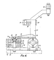
- each mould set includes a lower mould part 18 and an upper mould part 19.
- the part 18 includes a base plate 20 fixed on the turntable, and a bottom mould plate 21 secured on the base plate 20 with a member 23 of thermally insulating material located between them. Attached to the base plate are a pair of side plates 24 in which the opposite ends of a fulcrum pin 25 are journaled by bearings.
- the upper mould part 19 includes a pair of arms 26 carried on and keyed to the pin 25 and clamped to it by means of screws.
- the arms 26 carry a top mould plate 22 which co-operates with the bottom plate 21 to define the mould cavity, or in the case of the illustrated embodiment a pair of annular cavities 27.
- the plate 22 is not secured rigidly to the arms 26, but is capable of some translational and tilting movement.
- the connection between the plate 22 and each arm 26 is effected by a screw 28 which is adjusted to permit some movement between the plate and arm, and a belleville spring 29 is inserted between the plate 22 and arm 26.
- the pivotal mounting between the upper and lower mould parts 18, 19, allows the top plate 22 of the mould to be moved between a closed position surmounting the bottom plate 21, as shown in Figures 3 and 4 and the left hand side of Figure 2, and an open position displaced at 90° to the closed position and in which it is moved clear of the bottom plate as seen at the right hand side of Figure 2.
- the spring mounting of the top plate on the arms 26 enables it to be brought into ' correct alignment with the bottom plate each time the mould is closed, and to ensure that the plates become aligned automatically, the bottom plate is equipped with a pair of dowel pins 30 having tapered upper ends, and the top plate is provided with sockets fitted with ring inserts 31 to receive the dowel pins.
- the dowel pins 30 enter the rings 31 thereby adjusting the position of the top plate 22 to register precisely with the bottom plate 21.
- a lever 33 is keyed for rotation with the fulcrum pin 25.
- the lever 33 consists of a pair of parallel arms of L-shape which are interconnected at their free ends by a thrust block 34.
- a second lever 35 is pivoted between the arms of lever 33 on a pin 36 parallel to, but spaced from the pin 25.
- a strong coil compression spring 38 is inserted between the lever 35 and the thrust block and normally urges the lever 35 against a stop 39 fixed to the lever 33.
- the lever 35 carries rollers 40 which co-operate with a cam track 41 which is fixed on the frame 1 of the injection moulding machine and extends continuously around the axis of the rotor.
- the cam track is designed so that, as the mould sets 17 travel around on the turntable 12, they are opened and closed in accordance with a predetermined sequence of operations.
- the cam track 41 maintains the lever 35 and hence lever 33 in a generally horizontal position as shown at the right hand side of Figure 2, and when the mould is to be closed an inclined section of the cam track designated 42 in Figure 1 moves the levers 35, 33 to a generally vertical position, as shown at the left hand side of Figure 2.
- the cam track is adapted to push the end of lever 35 radially outwardly so that the spring 38 is compressed and the full force of this spring acts through the lever 33 and arms 26 to hold the top plate 22 firmly against the bottom plate 21.
- a further inclined cam track section designated 43 in Figure 1 adjusts the moulds from the closed position to the open position.
- the mould plates 20, 21 include passages 45 for circulation of thermal fluid to stabilise the mould temperature and accelerate curing of the moulding material in the mould.
- the particular fluid will be chosen in accordance with temperature requirements. It could be cooling-water in the case of thermoplastic moulding material, or it could be steam or as described below in the exemplary embodiment, hot water as the moulding material is thermosetting.
- annular inlet and outlet manifolds 50 an 51, respectively, are included in the rotor assembly and are mounted on the drive plate 10 by means of brackets 52.
- the manifolds 50, 51 are connected to the mould plates by pipelines 54 and are respectively connected to centrally located inlet tank 55 and outlet tank 56 by hoses 57.
- the tanks are supported on the rotor shaft 2 and are separated by a spacer 58.
- Hot water is fed to the inlet tank 55 by means of a rotary union 60, and the cooled water is discharged from the outlet tank 56 via a pipe 61 extending down through the centre of shaft 2, and a rotary union 62.
- the hot water circulates continuously, the flow path being inlet tank 55, inlet manifold 50, mould plates 21, 22, outlet manifold 51 and outlet tank 56.
- valves may be included in the pipelines 54 and can be operated by means of cams mounted on the machine frame.
- a clamping and injection assembly supported for reciprocal movement along an arcuate path centered on the axis of the machine rotor.
- a curved carrier plate 60 rests on support rollers 62 mounted on the machine frame 1, and a radial arm 64 journaled on the rotor shaft 2 and connected to the carrier plate by a pair of vertical tie bars 65 constrains the carrier plate 60 to move concentrically with the turntable 12.
- a fluid actuated ram 66 is coupled between the frame 1 and one of the tie bars 65 for effecting a return stroke of the carrier plate which is in the clockwise direction as seen in Figure 1.
- a latching device comprising a fluid cylinder 67 and a latching key 68 connected to the piston rod of the cylinder.
- the cylinder is'actuable to advance and retract the key 68 to engage and disengage the notches 16 formed in the periphery of the turntable 12.
- the clamping mechanism includes a pair of generally C-shaped brackets 70 each supported by a pair of parallel links 71, 72 pivoted to a vertical plate 73 upstanding from a mounting plate 74 which is fixed to the carrier plate 60.
- the vertical plates 73 and brackets 70 are spaced apart on either side of the latching mechanism 67, 68 as may be seen in Figure 1.
- the upper links 72 are fashioned as levers and at their ends opposite the brackets 70 carry rods 75 which are urged downwardly by springs 76 acting between the ends of the rods and stops fixed on plates 73.
- a clamping member 78 of generally U-shaped cross-section is carried by the brackets 70 and an upper limb of this member is arranged to extend over the turntable 12 for engaging the upper parts 19 of the mould sets.
- the lower limb of member 78 supports a fluid actuator 80 which is operable to push a pressure plate 81 up against the under-side of the turntable 12.
- the high clamping pressure applied by the actuator 80 holds the mould plates securely closed during injection of the moulding material into the mould cavities, it being essential to prevent parting of the mould plates at this stage if flash on the moulded plates is to be avoided.
- the pressure plate 81 is retracted by the actuator 80 and the clamping member 78 is lifted slightly under the action of springs 76 so as to be raised clear of the mould set.
- the clamping member 78 has an opening to enable the latching key 68 to move into co-operation with the turntable and this opening, or a further opening, allows an injection nozzle to be moved into co-operation with the clamped mould set.
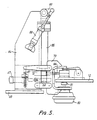
- the injection device has been omitted in Figures 1 and 2 for reasons of clarity, but is clearly illustrated in Figures 5 and 6. It comprises a vertical support 84 extending upwardly from and fixed to the carrier plate 60. Pivoted to the upper end of the support 84 in the manner of a pendulum is a member 85 which swings in a plane radial to the axis of the machine rotor and bisecting the high pressure clamping mechanism. The lower end of the member 85 carries the injection nozzle 86 and a control valve 87 to control supply of moulding material to the nozzle. The material is fed to the upper end of member 85 and passes down through this member to the control valve.
- the member can for example be constructed as a mixer for mixing the moulding material on its way to the injection nozzle and can include a temperature control jacket.
- the member 85 can also be designed to perform other operations to suit the particular material being used.
- a double acting fluid cylinder 88 is connected between a bracket on the support 84 and an arm 89 fast with the member 85.
- a control system is provided to ensure synchronised operation of the machine, including the reciprocation of the clamping and injection assembly, the actuation of the fluid actuators 66, 67, 80 and 88, and the operation of the control valve 87.
- the control system includes a mould sensor 90 for sensing when a mould set is in correct position to be clamped by the clamping mechanism, micro-switches 91 for sensing the end positions of the carrier plate movement, and an electrical control unit 92.
- Control valves for the fluid actuators are included in a further control box 93 also mounted on the machine frame.
- the mould set approaches the inclined cam track section 42 which by acting on the lever 35 closes the upper mould part 19 down on the lower part 18 and clamps the mould plates closed under the force of spring 38.
- Full closure of the mould is achieved shortly before the mould reaches the injection station at a position diametrically opposite the initial position.
- Arrival of the mould set at said position is detected by the sensor 90, which actually works by sensing the immediately following mould set, and in response to a signal from the sensor 90 the control system actuates the cylinder 67 of the latching mechanism to engage the key 68 in the adjacent notch 16 of the turntable so that the carrier plate, and hence the clamping and injection assembly, become locked to the turntable 12 and start to move around with it.
- the actuator 80 is activated so that the mould set becomes clamped under high pressure between the clamp member 78 and the pressure plate 81.
- the cylinder 88 is actuated to bring the injection nozzle 86 into co-operation with the inlet orifice of the mould set, and the control valve is opened for a preset time to inject a predetermined quantity of the moulding material into the cavities of the mould.
- the injection of material is completed during a small angle of rotation of the turntable, which in the illustrated embodiment is less than 10°, and before the carrier plate reaches the end of its forward stroke as determined by the microswitches 91.
- the material is not fully cured when the high clamping pressure is removed, it still remains closed under the reduced closing force exerted by the spring 38.
- the hot water flowing through the passages in the mould plates 21, 22 accelerates the curing process and by the time the mould set reaches the inclined cam track section 42 the material will be set sufficiently to be handled.
- the inclined cam track section 43 effects opening of the mould, the upper part 19 of the mould being moved upwardly and inwardly away from the lower part 18 to facilitate unobstructed removal of the finished articles.
- the mould set has then travelled through 360° and the described cycle is repeated.
- a moulding machine as described above has been constructed and tested and has proved highly successful in the manufacture of rings of silicone rubber. Because the clamping and injection assembly is arranged to move to and fro synchronously with rotation of the turntable, the turntable can be rotated continuously and problems associated with intermittent drive of a rotor with large inertia is avoided. By providing means to hold the moulds closed under spring force, a single high pressure clamping device can be employed to act on each mould set during injection of material and the machine construction is thereby simplified.
- the pivotal connection of the mould parts, as well as the spring mounting of the top mould plates contribute to the convenience of the machine by allowing unobstructed access to the opened moulds.
- the turntable has been described as having a gear and chain drive it will be understood that any mechanism capable of imparting continuous rotation to the turntable could be used.
- the mould carriers could be of integral construction, such as cast members.
- the parts 20, 24 may be combined in one casting and the arms 26 and parts 33 combined in another casting.
- the spring 38 could be arranged to act between the arms 26 and a lateral projection provided on the lever 35 and overlying the arms 26.
- the injection nozzle should be supported pivotally to be moved in a vertical plane as shown in Figures 5 and 6 and other arrangements are possible. All that is required is that the nozzle should be able to move into and out of engagement with each mould set, and it could alternatively be arranged to be pivoted in a horizontal plane or to be moved linearly in the radial direction.
Landscapes
- Engineering & Computer Science (AREA)
- Manufacturing & Machinery (AREA)
- Mechanical Engineering (AREA)
- Moulds For Moulding Plastics Or The Like (AREA)
- Injection Moulding Of Plastics Or The Like (AREA)
Priority Applications (1)
| Application Number | Priority Date | Filing Date | Title |
|---|---|---|---|
| AT85904009T ATE44681T1 (de) | 1984-08-13 | 1985-08-13 | Giessvorrichtung. |
Applications Claiming Priority (8)
| Application Number | Priority Date | Filing Date | Title |
|---|---|---|---|
| GB8420507 | 1984-08-13 | ||
| GB848420507A GB8420507D0 (en) | 1984-08-13 | 1984-08-13 | Injection moulding apparatus |
| GB848420505A GB8420505D0 (en) | 1984-08-13 | 1984-08-13 | Injection moulding apparatus |
| GB8420508 | 1984-08-13 | ||
| GB848420508A GB8420508D0 (en) | 1984-08-13 | 1984-08-13 | Injection moulding apparatus |
| GB8420505 | 1984-08-13 | ||
| GB848420506A GB8420506D0 (en) | 1984-08-13 | 1984-08-13 | Injection moulding apparatus |
| GB8420506 | 1984-08-13 |
Publications (2)
| Publication Number | Publication Date |
|---|---|
| EP0190276A1 EP0190276A1 (en) | 1986-08-13 |
| EP0190276B1 true EP0190276B1 (en) | 1989-07-19 |
Family
ID=27449580
Family Applications (1)
| Application Number | Title | Priority Date | Filing Date |
|---|---|---|---|
| EP85904009A Expired EP0190276B1 (en) | 1984-08-13 | 1985-08-13 | Moulding apparatus |
Country Status (5)
| Country | Link |
|---|---|
| US (1) | US4726757A (en, 2012) |
| EP (1) | EP0190276B1 (en, 2012) |
| DE (1) | DE3571576D1 (en, 2012) |
| IN (1) | IN164804B (en, 2012) |
| WO (1) | WO1986001145A1 (en, 2012) |
Families Citing this family (12)
| Publication number | Priority date | Publication date | Assignee | Title |
|---|---|---|---|---|
| JPS60245517A (ja) * | 1984-05-22 | 1985-12-05 | Toyo Seikan Kaisha Ltd | 圧縮成形装置 |
| JPS6435821A (en) * | 1987-07-31 | 1989-02-06 | Kita Nippon Densen Kk | Manufacture device for self-support type cable with sag |
| DE3823671C3 (de) * | 1988-07-13 | 1999-12-23 | Nissei Asb Machine Co Ltd | Vorrichtung zum Herstellen von Formteilen |
| WO1992011989A1 (en) * | 1991-01-03 | 1992-07-23 | David Rudy Brent | Apparatus and method for use in injection moulding |
| SG66304A1 (en) * | 1996-04-25 | 1999-07-20 | Fastech System S Pte Ltd | Injection moulding apparatus and method |
| US6012914A (en) * | 1998-05-12 | 2000-01-11 | Loulourgas; Demetre | Multi-color injection mold rotation apparatus |
| US6402504B1 (en) | 2000-06-07 | 2002-06-11 | Mgs Mfg. Group, Inc. | Rotary platen assembly |
| US7694702B2 (en) * | 2005-08-09 | 2010-04-13 | Adcor Industries, Inc. | Beverage machine assembly having a modular support |
| US7597834B2 (en) * | 2007-04-10 | 2009-10-06 | Husky Injection Molding Systems Ltd. | Rotary molding machine |
| CN102762351B (zh) * | 2009-12-24 | 2016-04-06 | 库尔蒂建筑机械有限公司 | 制造连接缆的设备和方法 |
| JP5814666B2 (ja) * | 2011-07-14 | 2015-11-17 | 住友重機械工業株式会社 | 射出成形機 |
| CN110978376A (zh) * | 2019-12-27 | 2020-04-10 | 苏州绿控新能源科技有限公司 | 一种分度注塑方法 |
Family Cites Families (7)
| Publication number | Priority date | Publication date | Assignee | Title |
|---|---|---|---|---|
| US2419089A (en) * | 1944-06-09 | 1947-04-15 | Ivar T Quarnstrom | Mold base |
| GB828994A (en) * | 1957-05-07 | 1960-02-24 | British Bata Shoe Co Ltd | Machine for manufacturing shoes and like articles of plastic material |
| US3293691A (en) * | 1964-05-15 | 1966-12-27 | El Tronics Inc | Rotary transfer injection molding machine |
| US3345687A (en) * | 1964-06-10 | 1967-10-10 | Gen Electric | Injection molding apparatus |
| US3856444A (en) * | 1972-10-05 | 1974-12-24 | J Saltel | Short-cycle molding device |
| US4186161A (en) * | 1974-01-04 | 1980-01-29 | Eastman Kodak Company | Method of continuous injection molding of plastic articles |
| CH589510A5 (en, 2012) * | 1974-12-02 | 1977-07-15 | Upjohn Co |
-
1985
- 1985-08-12 IN IN659/DEL/85A patent/IN164804B/en unknown
- 1985-08-13 EP EP85904009A patent/EP0190276B1/en not_active Expired
- 1985-08-13 DE DE8585904009T patent/DE3571576D1/de not_active Expired
- 1985-08-13 WO PCT/GB1985/000359 patent/WO1986001145A1/en active IP Right Grant
- 1985-08-13 US US06/859,089 patent/US4726757A/en not_active Expired - Lifetime
Also Published As
| Publication number | Publication date |
|---|---|
| IN164804B (en, 2012) | 1989-06-03 |
| WO1986001145A1 (en) | 1986-02-27 |
| US4726757A (en) | 1988-02-23 |
| EP0190276A1 (en) | 1986-08-13 |
| DE3571576D1 (en) | 1989-08-24 |
Similar Documents
| Publication | Publication Date | Title |
|---|---|---|
| EP0190276B1 (en) | Moulding apparatus | |
| KR920002360B1 (ko) | 사출 연신 블로우 성형 장치 | |
| EP0070189B1 (en) | Injection stretch-blow molding machine | |
| US7597834B2 (en) | Rotary molding machine | |
| US2518594A (en) | Injection molding machine and method | |
| KR950000179B1 (ko) | 연속 성형 방법 및 그의 장치 | |
| US4797084A (en) | Mold device for molding a preform | |
| US6638047B2 (en) | Molding machine | |
| US3877861A (en) | Blow moulding machine with cam controlled reciprocating carriage | |
| JPH01297231A (ja) | 複式射出成形用金型プレフォーム移送組立体 | |
| JPH07108554A (ja) | 発泡成形方法及び発泡成形装置 | |
| JP4319863B2 (ja) | 回転式成形機 | |
| GB864179A (en) | Injection moulding machine | |
| US5073329A (en) | Method for compressions moulding of elastomers | |
| US2564624A (en) | Method and means for making lipsticks | |
| US3293691A (en) | Rotary transfer injection molding machine | |
| US3611484A (en) | Apparatus for manufacture of hollow objects | |
| JPH0136768B2 (en, 2012) | ||
| GB2047608A (en) | Injection moulding apparatus | |
| US3746491A (en) | Injection molding apparatus | |
| EP0260932A2 (en) | Apparatus for forming tampon inserter tip | |
| US2900662A (en) | Molding machine | |
| JPS61503015A (ja) | 成型装置 | |
| EP2177331B1 (en) | Mould for manufacturing agglomerated cork stoppers | |
| JPS61154813A (ja) | 型締装置 |
Legal Events
| Date | Code | Title | Description |
|---|---|---|---|
| PUAI | Public reference made under article 153(3) epc to a published international application that has entered the european phase |
Free format text: ORIGINAL CODE: 0009012 |
|
| AK | Designated contracting states |
Kind code of ref document: A1 Designated state(s): AT BE CH DE FR GB IT LI LU NL SE |
|
| 17P | Request for examination filed |
Effective date: 19861224 |
|
| RIN1 | Information on inventor provided before grant (corrected) |
Inventor name: BERRY, FRANCIS DOUGLAS |
|
| 17Q | First examination report despatched |
Effective date: 19871021 |
|
| RAP1 | Party data changed (applicant data changed or rights of an application transferred) |
Owner name: WORLD HEALTH ORGANISATION |
|
| GRAA | (expected) grant |
Free format text: ORIGINAL CODE: 0009210 |
|
| AK | Designated contracting states |
Kind code of ref document: B1 Designated state(s): AT BE CH DE FR GB IT LI LU NL SE |
|
| REF | Corresponds to: |
Ref document number: 44681 Country of ref document: AT Date of ref document: 19890815 Kind code of ref document: T |
|
| ITF | It: translation for a ep patent filed | ||
| REF | Corresponds to: |
Ref document number: 3571576 Country of ref document: DE Date of ref document: 19890824 |
|
| ET | Fr: translation filed | ||
| PLBE | No opposition filed within time limit |
Free format text: ORIGINAL CODE: 0009261 |
|
| STAA | Information on the status of an ep patent application or granted ep patent |
Free format text: STATUS: NO OPPOSITION FILED WITHIN TIME LIMIT |
|
| 26N | No opposition filed | ||
| ITTA | It: last paid annual fee | ||
| EPTA | Lu: last paid annual fee | ||
| EAL | Se: european patent in force in sweden |
Ref document number: 85904009.9 |
|
| REG | Reference to a national code |
Ref country code: GB Ref legal event code: 732E |
|
| REG | Reference to a national code |
Ref country code: GB Ref legal event code: IF02 |
|
| PGFP | Annual fee paid to national office [announced via postgrant information from national office to epo] |
Ref country code: FR Payment date: 20030808 Year of fee payment: 19 |
|
| PGFP | Annual fee paid to national office [announced via postgrant information from national office to epo] |
Ref country code: LU Payment date: 20030813 Year of fee payment: 19 Ref country code: AT Payment date: 20030813 Year of fee payment: 19 |
|
| PGFP | Annual fee paid to national office [announced via postgrant information from national office to epo] |
Ref country code: CH Payment date: 20030818 Year of fee payment: 19 |
|
| PGFP | Annual fee paid to national office [announced via postgrant information from national office to epo] |
Ref country code: BE Payment date: 20031009 Year of fee payment: 19 |
|
| REG | Reference to a national code |
Ref country code: GB Ref legal event code: 732E |
|
| PGFP | Annual fee paid to national office [announced via postgrant information from national office to epo] |
Ref country code: GB Payment date: 20040811 Year of fee payment: 20 |
|
| PG25 | Lapsed in a contracting state [announced via postgrant information from national office to epo] |
Ref country code: LU Free format text: LAPSE BECAUSE OF NON-PAYMENT OF DUE FEES Effective date: 20040813 Ref country code: AT Free format text: LAPSE BECAUSE OF NON-PAYMENT OF DUE FEES Effective date: 20040813 |
|
| PGFP | Annual fee paid to national office [announced via postgrant information from national office to epo] |
Ref country code: NL Payment date: 20040823 Year of fee payment: 20 |
|
| PGFP | Annual fee paid to national office [announced via postgrant information from national office to epo] |
Ref country code: SE Payment date: 20040826 Year of fee payment: 20 Ref country code: DE Payment date: 20040826 Year of fee payment: 20 |
|
| PG25 | Lapsed in a contracting state [announced via postgrant information from national office to epo] |
Ref country code: LI Free format text: LAPSE BECAUSE OF NON-PAYMENT OF DUE FEES Effective date: 20040831 Ref country code: CH Free format text: LAPSE BECAUSE OF NON-PAYMENT OF DUE FEES Effective date: 20040831 Ref country code: BE Free format text: LAPSE BECAUSE OF NON-PAYMENT OF DUE FEES Effective date: 20040831 |
|
| BERE | Be: lapsed |
Owner name: *WORLD HEALTH ORGANISATION Effective date: 20040831 |
|
| REG | Reference to a national code |
Ref country code: CH Ref legal event code: PL |
|
| PG25 | Lapsed in a contracting state [announced via postgrant information from national office to epo] |
Ref country code: FR Free format text: LAPSE BECAUSE OF NON-PAYMENT OF DUE FEES Effective date: 20050429 |
|
| REG | Reference to a national code |
Ref country code: FR Ref legal event code: ST |
|
| PG25 | Lapsed in a contracting state [announced via postgrant information from national office to epo] |
Ref country code: GB Free format text: LAPSE BECAUSE OF EXPIRATION OF PROTECTION Effective date: 20050812 |
|
| PG25 | Lapsed in a contracting state [announced via postgrant information from national office to epo] |
Ref country code: NL Free format text: LAPSE BECAUSE OF EXPIRATION OF PROTECTION Effective date: 20050813 |
|
| REG | Reference to a national code |
Ref country code: GB Ref legal event code: PE20 |
|
| NLV7 | Nl: ceased due to reaching the maximum lifetime of a patent |
Effective date: 20050813 |
|
| EUG | Se: european patent has lapsed | ||
| BERE | Be: lapsed |
Owner name: *WORLD HEALTH ORGANISATION Effective date: 20040831 |