EP0190216B1 - Auf historische analyse gegründete rechnersystemeinheit-fehleridentifizierungsmethode - Google Patents
Auf historische analyse gegründete rechnersystemeinheit-fehleridentifizierungsmethode Download PDFInfo
- Publication number
- EP0190216B1 EP0190216B1 EP85903732A EP85903732A EP0190216B1 EP 0190216 B1 EP0190216 B1 EP 0190216B1 EP 85903732 A EP85903732 A EP 85903732A EP 85903732 A EP85903732 A EP 85903732A EP 0190216 B1 EP0190216 B1 EP 0190216B1
- Authority
- EP
- European Patent Office
- Prior art keywords
- unit
- list
- fault
- units
- prescribed
- Prior art date
- Legal status (The legal status is an assumption and is not a legal conclusion. Google has not performed a legal analysis and makes no representation as to the accuracy of the status listed.)
- Expired
Links
Images




Classifications
-
- G—PHYSICS
- G06—COMPUTING OR CALCULATING; COUNTING
- G06F—ELECTRIC DIGITAL DATA PROCESSING
- G06F11/00—Error detection; Error correction; Monitoring
- G06F11/07—Responding to the occurrence of a fault, e.g. fault tolerance
- G06F11/16—Error detection or correction of the data by redundancy in hardware
- G06F11/20—Error detection or correction of the data by redundancy in hardware using active fault-masking, e.g. by switching out faulty elements or by switching in spare elements
-
- G—PHYSICS
- G06—COMPUTING OR CALCULATING; COUNTING
- G06F—ELECTRIC DIGITAL DATA PROCESSING
- G06F11/00—Error detection; Error correction; Monitoring
- G06F11/07—Responding to the occurrence of a fault, e.g. fault tolerance
- G06F11/0703—Error or fault processing not based on redundancy, i.e. by taking additional measures to deal with the error or fault not making use of redundancy in operation, in hardware, or in data representation
- G06F11/0706—Error or fault processing not based on redundancy, i.e. by taking additional measures to deal with the error or fault not making use of redundancy in operation, in hardware, or in data representation the processing taking place on a specific hardware platform or in a specific software environment
- G06F11/0715—Error or fault processing not based on redundancy, i.e. by taking additional measures to deal with the error or fault not making use of redundancy in operation, in hardware, or in data representation the processing taking place on a specific hardware platform or in a specific software environment in a system implementing multitasking
-
- G—PHYSICS
- G06—COMPUTING OR CALCULATING; COUNTING
- G06F—ELECTRIC DIGITAL DATA PROCESSING
- G06F11/00—Error detection; Error correction; Monitoring
- G06F11/07—Responding to the occurrence of a fault, e.g. fault tolerance
- G06F11/0703—Error or fault processing not based on redundancy, i.e. by taking additional measures to deal with the error or fault not making use of redundancy in operation, in hardware, or in data representation
- G06F11/079—Root cause analysis, i.e. error or fault diagnosis
Definitions
- This invention relates to a method for controlling a processing unit to identify a faulty system unit, in a computer system comprising said processing unit, a peripheral unit, and at least one interface unit connecting the processing unit to the peripheral unit, and in which prescribed ones of the units include means for generating and returning error report messages to the processing unit in response to the detection of prescribed error conditions.
- Algorithm reliability that is, the ability to consistently and accurately identify a faulty unit in a complex system or subsystem, may be inadequate.
- the amount of dedicated software required to recover a system and to identify a faulty unit may become burdensome in a complex environment.
- the system time required to perform the recovery and identification steps may be intolerable, such as in a real-time environment of a telephone office.
- FR-A-2199418 discloses a method of generating and storing in a multiplicity of counters data relating to errors occurring intermittently during operation of a data handling system, the method comprising detecting errors occurring during operation of the system, producing error signals respectively indicative of the error detected, and, in response to the production of an error signal, increasing the counts in selected ones of the multiplicity of counters, the counters selected to be incremented and the amounts by which those counters are to be incremented being predetermined for each error signal.
- FIG. 1 shows a block diagram of an illustrative subsystem used to describe the invention. Specifically, the subsystem is contained in an electronic switching system known in the art.
- the subsystem of FIG. 1 consists of duplicated central processing units (CPUs) 0 and 1, one of which is active and one standby at any given time, for controlling operations of the subsystem, at least one switch module (SM) for establishing time-division multiplexed communication connections between a plurality of incoming and outgoing lines and trunks (not shown), and a complicated and highly redundant set of interface circuits providing alternative communication paths via which the CPUs control the operations of the switch module SM.
- CPUs central processing units
- SM switch module
- the illustrative interface units consist of duplicated message switch control units, MSCU 0 and MSCU 1, quadruplicated module message processors MMP 0A, MMP 0B, MMP 1A and MMP 1B, duplicated message interface units MICU 0 and MICU 1, and duplicated time multiplex switches TMS 0 and TMS 1.
- the interface units provide a total of eight alternative control communication paths 0 to 7 between the CPUs and the SM. These paths are shown in FIG. 1 as numerals located in the channels interconnecting the units. Thus, for example, communication paths 0, 2, 4 and 6 extend from either CPU 0 or CPU 1, whichever is active, to MSCU 0.
- paths 0 and 4 extend to MMP 0A, while paths 2 and 6 extend to MMP 0B.
- paths 0, 1, 2, and 3 proceed via MICU 0 to TMS 0, where two separate physical channels connect individual path pairs 0,1 and 2,3 to the switch module SM via a dual link interface (DLI) 0.
- paths 4 through 7 proceed via MICU 1 and TMS 1 to the SM via DLI 1.
- Each of the units detect various types of subsystem malfunctions while routing a control message from an active CPU to the SM.
- a unit detecting a malfunction generates and returns an error report having an error report number indicating the type of malfunction detected to the CPU via a separate communication channel not shown in FIG. 1.
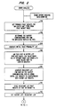
- the active CPU on receipt of an error report, initiates fault analysis and recovery by passing program control to the ERROR ANALYSIS program, whose flowcharts are shown beginning at FIG. 2 herein.
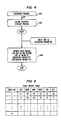
- ERROR ANALYSIS begins at step 200 by indexing into a fault weight table, shown in FIG. 5, with the number of the error message that has been received to obtain a set of probable fault weights for each type of unit in the subsystem of FIG. 1, except the SM.
- the fault weights in the fault weight table are predefined based on a mathematical model of the subsystem in question, taking into account the logical fault propagation dependencies of the subsystem, expected failure rates of the individual units based on their circuit structure and components, and any other factors that might characterize the failure modes of the subsystem.
- Step 202 obtains this information and determines the implicated units in the active communications path. Thus, if error message 2 is received and step 202 determines that CPU 0 is active and that the active communications path is 6, then it is seen from FIGS. 1 and 5 that the implicated units are CPU 0, MSCU 0, MMP 0B, MICU 1 and TMS 1. Step 204 generates an initial faulty probability list, illustrated in FIG. 6, containing the implicated units with their respective fault weights from the fault weight table.
- Step 206 next ages an existing error history list according to the elapsed time since the receipt of the last error report.
- the generation of the history list is discussed below.
- FIG. 7 shows an illustrative history list for purposes of discussion.
- the history list is assumed to contain the following fault weights before aging: MSCU 0-10%, MMP 0A-15%, TMS 1-50%.
- FIG. 8 shows the aged history list for this example, assuming that two seconds have elapsed between the previous error report and the present report.
- MSCU 0, MMP 0A and TMS 1 have aged fault weights of 0, 5 and 40 percent, respectively.
- Step 208 generates a resultant list of implicated units by adding the fault weights for the individual units from the initial list to the respective weights now present in the aged history list.
- a resultant list in the present example is shown in FIG. 9. By examining the initial list in FIG. 6 and the aged history list in FIG. 8, it is seen that the resultant list contains the following units with the following fault weights: CPU 0-5%, MSCU 0-30%, MMP 0A-5%, MMP 0B-40%, MICU 1-15%, TMS 1-50%, DLI 1-0%.
- the weights in the resultant list are scaled by step 210 so that no weights are larger than a preselected value N.
- the scaling is done by merely reducing any resultant fault weight greater than N to N.
- any given system there may be certain error reports that, when generated frequently by a particular type of unit, implicate another unit not otherwise implicated by such an error report.
- This is the case in the specific subsystem of FIG. 1 for a family of error reports generated by a MMP and identified for discussion here as AA, which at some point implicate an MSCU.
- An adaptation table illustratively shown in FIG. 11, is used to determine the point at which an MSCU is implicated.
- the adaptation table consists of several words, each of which contain a search parameter X which represents the number of MMPs in service at the beginning of an adaptation interval and a second parameter Z indicating a threshold level related to the number of error reports AA generated by the MMP.
- the threshold level is directly related to the difference between the number of active MMPs present at the beginning of an adaptation interval and the number of active MMPs present at the time of generation of subsequent error reports AA during the adaptation interval.
- the threshold can be viewed in these terms because, in general, an MMP is removed from service in response to a fixed number of successive error reports AA. Receipt of a first report AA initiates the adaptation interval. In response to receipt of an error report AA during the adaptation interval, the analysis program determines the number of presently active MMPs and then it determines if the threshold level has been exceeded. If so, it is concluded that the MSCU communicating with the MMP generating the last error report AA may be faulty.
- step 300 determines if the received error report is number AA. If not, the adaptation process is bypassed. If so, an adaptation timer is tested for the value zero by step 304.
- the adaptation timer defines the adaptation interval during which the threshold level must occur to implicate an MSCU. If the content of the adaptation timer is zero, step 306 initializes the timer to an illustrative 90 second interval to begin the adaptation interval.
- Step 308 saves the number of MMPs active at this time in a variable X.
- Step 316 searches the X parameter of the adaptation table in FIG. 11 for an entry containing a number equal to the number of presently active MMPs. When this is found, step 318 reads the threshold level contained in the second entry of the table and sets variable Z to this value.
- Step 310 now proceeds with normal analysis by masking the resultant and initial lists to get a final selection list from which a most probable faulty unit is selected.
- Masking in this context means preserving in the selection list the fault weights contained in the resultant list for all units that are present in both the resultant and initial lists.
- FIG. 10 An illustrative selection list generated by step 310 in the present example is shown in FIG. 10.
- the selection list contains entries for CPU 0, MSCU 0, MMP 0B, MICU 1 and TMS 1, since these units have non-zero fault weights in both the initial and resultant lists.
- the fault weights in the selection list for these units are taken from the resultant list.
- step 312 determines this unit, which is TMS 1 in the present example, removes it from service and schedules additional diagnostic tests to be executed on the unit to pinpoint the location of the fault within the unit.
- Step 304 determines if the adaptation timer initially set to an illustrative 90 seconds has expired. If so, the timer is reinitialized by step 306 and analysis with respect to this error report continues as already discussed. On the other hand, if the timer is not equal to 0, then an error report AA from a MMP was received in the recent past, thereby possibly implicating a MSCU as faulty. To determine if this is so, step 314 determines the number of presently active MMPs and sets a variable Y to this value.
- a strategy illustrated in FIG. 4 is provided to minimize the effects of erroneous fault unit selection and, in such a case, to help assure that eventually the correct fault unit will be found.
- a diagnostic process executed on a unit declared as faulty by the above-described method is illustrated by step 400.
- the results of a diagnostic process are a confirmation of a unit fault or an all tests pass (ATP) condition. This latter event may suggest an incorrect selection by the fault analysis process.
- ATP all tests pass
- step 404 reduces the fault weight for the unit in the history list by the value of the reduction parameter, but not to a resulting value less than zero. This action lessens the historical fault implication attributed to the identified unit for purposes of the next error report.
Landscapes
- Engineering & Computer Science (AREA)
- Theoretical Computer Science (AREA)
- Quality & Reliability (AREA)
- Physics & Mathematics (AREA)
- General Engineering & Computer Science (AREA)
- General Physics & Mathematics (AREA)
- Health & Medical Sciences (AREA)
- Biomedical Technology (AREA)
- Hardware Redundancy (AREA)
- Test And Diagnosis Of Digital Computers (AREA)
- Debugging And Monitoring (AREA)
- Monitoring And Testing Of Exchanges (AREA)
- Telephonic Communication Services (AREA)
Claims (11)
- Verfahren zum Steuern einer Prozessoreinheit zwecks Identifizierung einer fehlerhaften Systemeinheit in einem Rechnersystem (Fig. 1), das die Prozessoreinheit (CPU), eine periphere Einheit (SM) und wengistens eine die Prozessoreinheit (CPU) mit der peripheren Einheit (SM) verbindende Schnittstelleneinheit (MCSU, MMP, MICU, TMS, DLI) aufweist und in dem vorgegebene Einheiten Einrichtungen zur Erzeugung und Rückgabe von Fehlerberichtnachrichten an die Prozessoreinheit (CPU) unter Ansprechen auf die Feststellung vorgegebener Fehlerbedingungen enthalten, mit den Verfahrensschritten: Identifizieren eines vordefinierten Fehlertyps bei Empfang einer Fehlerberichtnachricht,
Ableiten (204) einer Anfangsliste (Fig. 6) vorgegebener Fehlerwahrscheinlichkeitsbewertungen aus einer dem Fehlertyp entsprechenden Eintragung in einer Fehlerbewertungstabelle (Fig. 5), wobei die Anfangsliste dadurch gewonnen wird, daß jeder Einheit einer ersten Gruppe wenigstens einer vorbestimmten Einheit eine erste spezielle Fehlerwahrscheinlichkeitsbewertung zugeordnet wird,
Speichern einer Vorgeschichtsliste (Fig. 7) von Fehlerbewertungen, wobei die Vorgeschichtsliste zu Anfang dadurch gewonnen wird, daß jeder Einheit einer zweiten Gruppe von vorbestimmten Einheiten eine zweite spezielle Fehlerwahrscheinlichkeitsbewertung zugeordnet wird,
Benutzen der Anfangsliste zur Aktualisierung der Vorgeschichtsliste, wobei die Aktualisierung eine Kombination der ersten Fehlerbewertungsliste mit der zweiten Fehlerbewertungsliste entsprechend einem ersten vorgegebenen Algorythmus für jede Einheit umfaßt, die sowohl zur Anfangsliste als auch zur Vorgeschichtsliste gehört, und
Auswählen (310) derjenigen Einheit als Fehlerhafte Einheit, die die größte Fehlerbewertung in der aktualisierten Vorgeschichtsliste besitzt,
gekennzeichnet durch:
Altern (206) der Vorgeschichtsliste vor Erzeugen der aktualisierten Vorgeschichtsliste durch Reduzieren der Fehlerbewertungen für jede Einheit in der Vorgeschichtsliste entsprechend einem zweiten vorgegebenen Algorythmus auf der Grundlage der seit Empfang der letzten Fehlerberichtnachricht verstrichenen Zeit. - Verfahren nach Anspruch 1,
bei dem vorgegebene Einheiten verdoppelt und neu konfigurierbar sind, um eine Vielzahl alternativer Nachrichtenwege zwischen der Prozessoreinheit (CPU) und der peripheren Einheit (SM) zu bilden, wobei die Prozessoreinheit (CPU) mit der peripheren Einheit (SM) durch einen aktiven Nachrichtenweg der Vielzahl von alternativen Nachrichtenwegen verbunden ist und die erste Gruppe von Einheiten durch folgende Verfahrensschritte bestimmt wird: Bestimmen (202) des aktiven Nachrichtenweges für den Zeitpunkt, zu dem die Fehlerberichtnachricht empfangen worden ist, und Bestimmen (202) der individuellen Einheiten auf dem so bestimmten aktiven Nachrichtenweg. - Verfahren nach Anspruch 1,
bei dem der Schritt des Alterns der Vorgeschichtsliste den Schritt umfaßt:
Reduzieren (206) der Fehlerwahrscheinlichkeitsbewertung für jede Einheit in der Vorgeschichtsliste um einen Betrag, der gleich einer vorgegebenen Konstante multipliziert mit einer Darstellung der Zeit ist, die seit Empfang der letzten Fehlerberichtnachricht verstrichen ist. - Verfahren nach Anspruch 3,
bei dem die Darstellung der verstrichenen Zeit die Anzahl von Sekunden ist (206), die seit Empfang der letzten Fehlerberichtnachricht verstrichen sind. - Verfahren nach Anspruch 1,
bei dem der erste vorgegebene Algorythmus bei der Aktualisierung der Vorgeschichtsliste aus einer Addition (208) der ersten Fehlerbewertungsliste zur zweiten Fehlerbewertungsliste besteht. - Verfahren nach Anspruch 1,
bei dem der Schritt der Auswahl einer fehlerhaften Einheit den Schritt umfaßt:
Erzeugen einer Auswahlliste (310) von Einheiten, die sowohl der Anfangsliste als auch der aktualisierten Vorgeschichtsliste gemeinsam sind, wobei die Auswahlliste für jede enthaltene Einheit die Fehlerbewertung der Einheit aus der aktualisierten Vorgeschichtsliste enthält. - Verfahren nach Anspruch 1,
bei dem eine Vielzahl vordefinierter Fehlertypen vorhanden ist und folgende weitere Verfahrensschritte vorgesehen sind:
Ansprechen auf eine erste Fehlerberichtnachricht mit einem vorgegebenen Fehlertyp der Vielzahl vorgegebener Fehlertypen durch Starten eines vorgegebenen Zeitintervalls (306) und Erzeugen eines vorgegebenen Schwellenwertes (Z), der zu der Anzahl von Fehlerberichtnachrichten des vorgegebenen Fehlertyps in Beziehung steht, und
Ansprechen auf eine zweite Fehlerberichtnachricht mit dem vorgegebenen Fehlertyp, die innerhalb des vorgegebenen Zeitintervalls empfangen wird, in dem eine erste vorgegebene Systemeinheit als fehlerhaft ausgewählt wird (322), wenn der vorgegebene Schwellenwert überschritten wird. - Verfahren nach Anspruch 7,
bei dem der vorgegebene Schwellenwert bei der Auswahl einer ersten vorgegebenen Systemeinheit als fehlerhafte Einheit überschritten wird, wenn die Differenz zwischen der Anzahl (X) zweiter, vorgegebener und verdoppelter Einheiten, die zu dem Zeitpunkt des Empfangs der ersten Fehlerberichtnachricht in der Rechneranlage aktiv waren, und der Anzahl (Y) der zweiten, vorgegebenen und verdoppelten Einheiten, die zu dem Zeitpunkt des Empfangs der zweiten Fehlerberichtnachricht in der Rechneranlage aktiv waren, größer als der vorgegebenen Schwellenwert (Z) ist. - Verfahren nach Anspruch 7,
bei dem die erste vorgegebene Systemeinheit mit einer Vielzahl der zweiten, vorgegebenen Einheiten der verdoppelten Einheiten in Verbindung steht. - Verfahren nach Anspruch 8,
bei dem der vorgegebene Schwellenwert (Z) durch Ausführen des folgenden Verfahrensschrittes erzeugt wird:
Durchsuchen einer Tabelle von Schwellenwerten (Fig. 11) nach einer Eintragung, die der Anzahl (X) der zweiten, vorgegebenen Einheiten der verdoppelten Einheiten entspricht, und Verwenden des Wertes dieser Eintragung als Wert für den vorgegebenen Schwellenwert (Z). - Verfahren nach Anspruch 1,
mit den Verfahrensschritten:
Durchführen (400) von Diagnoseprüfungen für die als fehlerhaft ausgewählte Einheit, um den Fehlerzustand zu bestätigen, und abhängig davon, daß bei den Diagnoseprüfungen alle Prüfungen bestanden worden sind, Reduzieren (404) der Fehlerbewertung für die gewählte Einheit in der vorgeschichtsliste um einen vorgegebenen Betrag auf einen Betrag, der nicht kleiner als Null ist.
Applications Claiming Priority (2)
| Application Number | Priority Date | Filing Date | Title |
|---|---|---|---|
| US634461 | 1984-07-26 | ||
| US06/634,461 US4633467A (en) | 1984-07-26 | 1984-07-26 | Computer system fault recovery based on historical analysis |
Publications (2)
| Publication Number | Publication Date |
|---|---|
| EP0190216A1 EP0190216A1 (de) | 1986-08-13 |
| EP0190216B1 true EP0190216B1 (de) | 1991-12-04 |
Family
ID=24543883
Family Applications (1)
| Application Number | Title | Priority Date | Filing Date |
|---|---|---|---|
| EP85903732A Expired EP0190216B1 (de) | 1984-07-26 | 1985-06-24 | Auf historische analyse gegründete rechnersystemeinheit-fehleridentifizierungsmethode |
Country Status (6)
| Country | Link |
|---|---|
| US (1) | US4633467A (de) |
| EP (1) | EP0190216B1 (de) |
| JP (1) | JPH0772871B2 (de) |
| CA (1) | CA1227875A (de) |
| DE (1) | DE3584835D1 (de) |
| WO (1) | WO1986001019A1 (de) |
Families Citing this family (50)
| Publication number | Priority date | Publication date | Assignee | Title |
|---|---|---|---|---|
| JPH0680492B2 (ja) * | 1984-09-29 | 1994-10-12 | 株式会社日立製作所 | エラー回復方法 |
| US4710926A (en) * | 1985-12-27 | 1987-12-01 | American Telephone And Telegraph Company, At&T Bell Laboratories | Fault recovery in a distributed processing system |
| US4970644A (en) * | 1987-01-02 | 1990-11-13 | Schlumberger Technology Corporation | Reconfigurable well logging system |
| US4829520A (en) * | 1987-03-16 | 1989-05-09 | American Telephone And Telegraph Company, At&T Bell Laboratories | In-place diagnosable electronic circuit board |
| US5065311A (en) * | 1987-04-20 | 1991-11-12 | Hitachi, Ltd. | Distributed data base system of composite subsystem type, and method fault recovery for the system |
| ATE78114T1 (de) * | 1987-04-22 | 1992-07-15 | Ibm | Adapterbusschalter zur verbesserung der verfuegbarkeit einer steuereinheit. |
| DE3719283A1 (de) * | 1987-06-10 | 1988-12-22 | Bosch Gmbh Robert | Verfahren zur lokalisierung defekter stationen in lokalen netzwerken und dazugehoeriger schnittstellencontroller |
| CA1318030C (en) * | 1988-03-30 | 1993-05-18 | Herman Polich | Expert system for identifying failure points in a digital data processing system |
| US5090014A (en) * | 1988-03-30 | 1992-02-18 | Digital Equipment Corporation | Identifying likely failure points in a digital data processing system |
| US4924466A (en) * | 1988-06-30 | 1990-05-08 | International Business Machines Corp. | Direct hardware error identification method and apparatus for error recovery in pipelined processing areas of a computer system |
| JPH02297228A (ja) * | 1989-05-11 | 1990-12-07 | Fujitsu Ltd | 障害情報格納方式 |
| US5107497A (en) * | 1989-07-28 | 1992-04-21 | At&T Bell Laboratories | Technique for producing an expert system for system fault diagnosis |
| US5157667A (en) * | 1990-04-30 | 1992-10-20 | International Business Machines Corporation | Methods and apparatus for performing fault isolation and failure analysis in link-connected systems |
| US5200958A (en) * | 1990-09-28 | 1993-04-06 | Xerox Corporation | Method and apparatus for recording and diagnosing faults in an electronic reprographic printing system |
| US5313628A (en) * | 1991-12-30 | 1994-05-17 | International Business Machines Corporation | Component replacement control for fault-tolerant data processing system |
| US5483468A (en) * | 1992-10-23 | 1996-01-09 | International Business Machines Corporation | System and method for concurrent recording and displaying of system performance data |
| US5432932A (en) * | 1992-10-23 | 1995-07-11 | International Business Machines Corporation | System and method for dynamically controlling remote processes from a performance monitor |
| US5506955A (en) * | 1992-10-23 | 1996-04-09 | International Business Machines Corporation | System and method for monitoring and optimizing performance in a data processing system |
| US5553235A (en) * | 1992-10-23 | 1996-09-03 | International Business Machines Corporation | System and method for maintaining performance data in a data processing system |
| US5528516A (en) | 1994-05-25 | 1996-06-18 | System Management Arts, Inc. | Apparatus and method for event correlation and problem reporting |
| FR2724026B1 (fr) * | 1994-08-29 | 1996-10-18 | Aerospatiale | Procede et dispositif pour l'identification de pannes dans un systeme complexe |
| US5737600A (en) * | 1994-09-12 | 1998-04-07 | International Business Machines Corporation | Method and system for log management in a coupled data processing system |
| US5790779A (en) * | 1995-03-10 | 1998-08-04 | Microsoft Corporation | Method and system for consolidating related error reports in a computer system |
| US5729733A (en) * | 1995-05-05 | 1998-03-17 | Harris Corporation | Method of operating a distributed databse based on object ownership and transaction classification utilizing an aggressive reverse one phase commit protocol |
| KR0174604B1 (ko) * | 1995-07-24 | 1999-04-01 | 김광호 | 전자식 교환기에서 프로세서 상태확인 분산처리방법 |
| JP3137056B2 (ja) * | 1997-11-19 | 2001-02-19 | 日本電気株式会社 | 故障伝搬経路抽出システム及びその方法並びにその制御プログラムを記録した記録媒体 |
| US7013305B2 (en) | 2001-10-01 | 2006-03-14 | International Business Machines Corporation | Managing the state of coupling facility structures, detecting by one or more systems coupled to the coupling facility, the suspended state of the duplexed command, detecting being independent of message exchange |
| US6385665B1 (en) * | 1998-12-18 | 2002-05-07 | Alcatel Usa Sourcing, L.P. | System and method for managing faults in a data transmission system |
| US6622264B1 (en) * | 1999-10-28 | 2003-09-16 | General Electric Company | Process and system for analyzing fault log data from a machine so as to identify faults predictive of machine failures |
| JP3555071B2 (ja) * | 1999-07-06 | 2004-08-18 | Necエレクトロニクス株式会社 | 故障伝搬経路推定方法、故障伝搬経路推定装置及び記録媒体 |
| US6598179B1 (en) | 2000-03-31 | 2003-07-22 | International Business Machines Corporation | Table-based error log analysis |
| US6820213B1 (en) | 2000-04-13 | 2004-11-16 | Stratus Technologies Bermuda, Ltd. | Fault-tolerant computer system with voter delay buffer |
| US6687851B1 (en) | 2000-04-13 | 2004-02-03 | Stratus Technologies Bermuda Ltd. | Method and system for upgrading fault-tolerant systems |
| US6871299B2 (en) * | 2001-02-05 | 2005-03-22 | Fisher-Rosemount Systems, Inc. | Hierarchical failure management for process control systems |
| US7065672B2 (en) | 2001-03-28 | 2006-06-20 | Stratus Technologies Bermuda Ltd. | Apparatus and methods for fault-tolerant computing using a switching fabric |
| DE10144006A1 (de) * | 2001-09-07 | 2003-04-30 | Siemens Ag | Verfahren zur Meldungsdiagnose |
| US7159146B2 (en) * | 2002-05-14 | 2007-01-02 | Sun Microsystems, Inc. | Analyzing system error messages |
| US7055071B2 (en) * | 2003-01-09 | 2006-05-30 | International Business Machines Corporation | Method and apparatus for reporting error logs in a logical environment |
| US7143236B2 (en) * | 2003-07-30 | 2006-11-28 | Hewlett-Packard Development Company, Lp. | Persistent volatile memory fault tracking using entries in the non-volatile memory of a fault storage unit |
| US7142960B2 (en) * | 2004-10-14 | 2006-11-28 | Snap-On Incorporated | Prioritized test procedure and step display using statistical feedback |
| US7409595B2 (en) * | 2005-01-18 | 2008-08-05 | International Business Machines Corporation | History-based prioritizing of suspected components |
| JP4527642B2 (ja) * | 2005-09-29 | 2010-08-18 | 富士通株式会社 | ネットワーク障害診断装置、ネットワーク障害診断方法およびネットワーク障害診断プログラム |
| US20090300430A1 (en) * | 2008-06-02 | 2009-12-03 | Orit Nissan-Messing | History-based prioritizing of suspected components |
| JP5439775B2 (ja) * | 2008-09-17 | 2014-03-12 | 富士通株式会社 | 障害対応プログラム、障害対応装置、及び障害対応システム |
| US8595553B2 (en) * | 2010-06-03 | 2013-11-26 | Siemens Aktiengesellschaft | Error pattern identification in an installed base of systems |
| US9311176B1 (en) * | 2012-11-20 | 2016-04-12 | Emc Corporation | Evaluating a set of storage devices and providing recommended activities |
| JP5875726B1 (ja) * | 2015-06-22 | 2016-03-02 | 株式会社日立パワーソリューションズ | 異常予兆診断装置のプリプロセッサ及びその処理方法 |
| US11971798B2 (en) | 2019-09-25 | 2024-04-30 | Nec Corporation | Operation management apparatus, system, method, and non-transitory computer readable medium storing program |
| US11815560B2 (en) * | 2020-02-12 | 2023-11-14 | Dit-Mco International Llc | Methods and systems for wire harness test results analysis |
| CN119645691B (zh) * | 2023-09-11 | 2026-03-27 | 昆仑芯(北京)科技股份有限公司 | 故障处理方法及装置、设备和介质 |
Family Cites Families (7)
| Publication number | Priority date | Publication date | Assignee | Title |
|---|---|---|---|---|
| DE2244598B2 (de) * | 1972-09-12 | 1975-12-18 | Ibm Deutschland Gmbh, 7000 Stuttgart | Verfahren zur Gewinnung und Auswertung von Fehleranalysedaten auf der Basis von in einem System austauschbaren, justierbaren oder reparierbaren Einheiten |
| DE2654389C3 (de) * | 1976-12-01 | 1980-07-31 | Ibm Deutschland Gmbh, 7000 Stuttgart | Wartungssteuerung mit Prozessor und Speicher zur Fehleranalyse und -diagnose für elektronische Datenverarbeitungsanlagen und Verfahren zu deren Betrieb |
| JPS594054B2 (ja) * | 1979-04-17 | 1984-01-27 | 株式会社日立製作所 | マルチプロセツサ障害検出方式 |
| US4380067A (en) * | 1981-04-15 | 1983-04-12 | International Business Machines Corporation | Error control in a hierarchical system |
| US4438494A (en) * | 1981-08-25 | 1984-03-20 | Intel Corporation | Apparatus of fault-handling in a multiprocessing system |
| US4517639A (en) * | 1982-05-13 | 1985-05-14 | The Boeing Company | Fault scoring and selection circuit and method for redundant system |
| US4503535A (en) * | 1982-06-30 | 1985-03-05 | Intel Corporation | Apparatus for recovery from failures in a multiprocessing system |
-
1984
- 1984-07-26 US US06/634,461 patent/US4633467A/en not_active Expired - Lifetime
-
1985
- 1985-06-24 DE DE8585903732T patent/DE3584835D1/de not_active Expired - Lifetime
- 1985-06-24 JP JP60503319A patent/JPH0772871B2/ja not_active Expired - Lifetime
- 1985-06-24 WO PCT/US1985/001219 patent/WO1986001019A1/en not_active Ceased
- 1985-06-24 EP EP85903732A patent/EP0190216B1/de not_active Expired
- 1985-06-28 CA CA000485801A patent/CA1227875A/en not_active Expired
Also Published As
| Publication number | Publication date |
|---|---|
| JPS61502847A (ja) | 1986-12-04 |
| US4633467A (en) | 1986-12-30 |
| WO1986001019A1 (en) | 1986-02-13 |
| CA1227875A (en) | 1987-10-06 |
| EP0190216A1 (de) | 1986-08-13 |
| JPH0772871B2 (ja) | 1995-08-02 |
| DE3584835D1 (de) | 1992-01-16 |
Similar Documents
| Publication | Publication Date | Title |
|---|---|---|
| US4633467A (en) | Computer system fault recovery based on historical analysis | |
| US5675724A (en) | Knowledge based resource management | |
| CA1267226A (en) | Fault recovery in a distributed processing system | |
| Downing et al. | No. 1 ESS maintenance plan | |
| US8675805B2 (en) | Automated periodic surveillance testing method and apparatus in digital reactor protection system | |
| US5740357A (en) | Generic fault management of a computer system | |
| EP0263773B1 (de) | Symmetriebildung für redundante Kanäle | |
| US5740157A (en) | Distributed control methodology and mechanism for implementing automatic protection switching | |
| US5561760A (en) | System for localizing field replaceable unit failures employing automated isolation procedures and weighted fault probability encoding | |
| US5551047A (en) | Method for distributed redundant execution of program modules | |
| US6385665B1 (en) | System and method for managing faults in a data transmission system | |
| EP0399308A2 (de) | Rechnernetzwerk zur Echtzeitsteuerung mit automatischer Fehleridentifikation und -umgehung | |
| US5487149A (en) | Common control redundancy switch method for switching a faulty active common control unit with an inactive spare common control unit | |
| EP0102059A2 (de) | Datenübertragungsgerät für Ringübertragungssystem | |
| JPH0793624B2 (ja) | リンク結合システム内の故障を分離し分析する装置及び方法 | |
| US7073088B2 (en) | Data bus arrangement and control method for efficiently compensating for faulty signal lines | |
| Bowman et al. | 1a processor: Maintenance software | |
| CN115598961B (zh) | 一种冗余切换仲裁方法、装置及电子介质 | |
| JP3395288B2 (ja) | 情報処理装置と情報処理方法 | |
| Tsiang et al. | Maintenance of a large electronic switching system | |
| KR940010206B1 (ko) | 데이타 전송장치에서의 유니트(1:1) 절체회로 | |
| CN117478492A (zh) | 一种时钟系统的故障诊断方法、装置及时钟系统 | |
| JPH0955797A (ja) | 障害解析自動診断処理方法 | |
| Tuomenoksa et al. | Problems of programming for shared real-time systems | |
| EP0522759B1 (de) | Schaltung zur zuverlässigen Umschaltung von signalverarbeitenden Schaltungen |
Legal Events
| Date | Code | Title | Description |
|---|---|---|---|
| PUAI | Public reference made under article 153(3) epc to a published international application that has entered the european phase |
Free format text: ORIGINAL CODE: 0009012 |
|
| AK | Designated contracting states |
Kind code of ref document: A1 Designated state(s): BE DE FR GB IT NL SE |
|
| 17P | Request for examination filed |
Effective date: 19860729 |
|
| RIN1 | Information on inventor provided before grant (corrected) |
Inventor name: VEACH, MICHAEL, THOMAS Inventor name: POLLI, PHILIP, VAUGHN Inventor name: KWAN, CHI, LEUNG Inventor name: ABEL, MARK, JEFFREY MUNICH 70, WEST GERMANY |
|
| RIN1 | Information on inventor provided before grant (corrected) |
Inventor name: VEACH, MICHAEL, THOMAS Inventor name: POLLI, PHILIP, VAUGHN Inventor name: KWAN, CHI, LEUNG Inventor name: ABEL, MARK, JEFFREY |
|
| 17Q | First examination report despatched |
Effective date: 19890628 |
|
| GRAA | (expected) grant |
Free format text: ORIGINAL CODE: 0009210 |
|
| AK | Designated contracting states |
Kind code of ref document: B1 Designated state(s): BE DE FR GB IT NL SE |
|
| PG25 | Lapsed in a contracting state [announced via postgrant information from national office to epo] |
Ref country code: SE Effective date: 19911204 Ref country code: NL Effective date: 19911204 Ref country code: BE Effective date: 19911204 |
|
| REF | Corresponds to: |
Ref document number: 3584835 Country of ref document: DE Date of ref document: 19920116 |
|
| ET | Fr: translation filed | ||
| ITF | It: translation for a ep patent filed | ||
| NLV1 | Nl: lapsed or annulled due to failure to fulfill the requirements of art. 29p and 29m of the patents act | ||
| PLBE | No opposition filed within time limit |
Free format text: ORIGINAL CODE: 0009261 |
|
| STAA | Information on the status of an ep patent application or granted ep patent |
Free format text: STATUS: NO OPPOSITION FILED WITHIN TIME LIMIT |
|
| 26N | No opposition filed | ||
| PGFP | Annual fee paid to national office [announced via postgrant information from national office to epo] |
Ref country code: GB Payment date: 20010525 Year of fee payment: 17 Ref country code: FR Payment date: 20010525 Year of fee payment: 17 |
|
| PGFP | Annual fee paid to national office [announced via postgrant information from national office to epo] |
Ref country code: DE Payment date: 20010629 Year of fee payment: 17 |
|
| REG | Reference to a national code |
Ref country code: GB Ref legal event code: IF02 |
|
| PG25 | Lapsed in a contracting state [announced via postgrant information from national office to epo] |
Ref country code: GB Free format text: LAPSE BECAUSE OF NON-PAYMENT OF DUE FEES Effective date: 20020624 |
|
| PG25 | Lapsed in a contracting state [announced via postgrant information from national office to epo] |
Ref country code: DE Free format text: LAPSE BECAUSE OF NON-PAYMENT OF DUE FEES Effective date: 20030101 |
|
| GBPC | Gb: european patent ceased through non-payment of renewal fee |
Effective date: 20020624 |
|
| PG25 | Lapsed in a contracting state [announced via postgrant information from national office to epo] |
Ref country code: FR Free format text: LAPSE BECAUSE OF NON-PAYMENT OF DUE FEES Effective date: 20030228 |
|
| REG | Reference to a national code |
Ref country code: FR Ref legal event code: ST |