EP0189686A2 - Vorrichtung zur Leistung von Diensten oder zur Abgabe von Waren gegen Vorauszahlung - Google Patents
Vorrichtung zur Leistung von Diensten oder zur Abgabe von Waren gegen Vorauszahlung Download PDFInfo
- Publication number
- EP0189686A2 EP0189686A2 EP85402292A EP85402292A EP0189686A2 EP 0189686 A2 EP0189686 A2 EP 0189686A2 EP 85402292 A EP85402292 A EP 85402292A EP 85402292 A EP85402292 A EP 85402292A EP 0189686 A2 EP0189686 A2 EP 0189686A2
- Authority
- EP
- European Patent Office
- Prior art keywords
- box
- compartment
- post
- door
- drawer
- Prior art date
- Legal status (The legal status is an assumption and is not a legal conclusion. Google has not performed a legal analysis and makes no representation as to the accuracy of the status listed.)
- Ceased
Links
Images


Classifications
-
- G—PHYSICS
- G07—CHECKING-DEVICES
- G07F—COIN-FREED OR LIKE APPARATUS
- G07F9/00—Details other than those peculiar to special kinds or types of apparatus
- G07F9/06—Coin boxes
Definitions
- the present invention relates to a device for dispensing prepaid products or services comprising a post fixed to the ground including a closable compartment containing a removable coin box, and a box which can be fixed on the post.
- All these devices include mechanical and electromechanical devices which are partly contained in the post and partly contained in the box, and have at least two locked inputs for accessing the devices in the device.
- One of these entrances is a pivoting door closing the box compartment which, very often, is separated from the other devices contained in the post by partitions.
- Another entry is a box door or a locking device to remove part of the box.
- an agent responsible for lifting the coin box and also for maintaining the device must carry out several separate, often complex, operations to open the compartment, remove the box and gain access to the interior of the post and the box. .
- the manipulations are often long and troublesome due to measures to increase the safety and robustness of the device.
- the object of the invention is to provide a dispensing device which obviates the above-mentioned drawbacks and particularly, offering only a single entry to allow access to the box compartment and to the devices internal to the device and requiring only one. continuous operation to extract the box outwards and unlock the box from the post.
- the box and the post are robust and offer no roughness, the device is practically protected against vandalism.
- a dispensing device as defined in the introduction is characterized in that it comprises means for concomitantly opening the compartment, removing the box from the compartment and unlocking the box from the post in order to access means contained in the post and the box.
- the apparatus comprises means for simultaneously translating the box and a door closing the compartment towards the outside of the post, and means controllable from the open compartment to unlock the box from the post.
- the means for translating are pivotable when the box and the door are outside the post, and are connected to the means for unlocking.
- a pivoting of the means for translating causes the box to be unlocked relative to the post by means of the means for unlocking.
- the device comprises contact means cooperating mechanically with a surface of the box and / or with a portion of the door of the compartment to signal an abnormal absence of the box in the compartment and / or an abnormal opening of the compartment respectively.
- a signaling can be carried out by means of a loudspeaker diffusing an audible alarm signal and / or a telephone transmitter transmitting an alarm signal through a telephone line in order to notify surveillance services, such as police.
- security of access to the compartment is improved by means of a storm door fixed against the door closing the box compartment.
- Contact means cooperating with an internal portion of the storm door are provided to signal an undesirable distance of the storm door relative to the door.
- the invention provides means avoiding to a large extent a tearing off of the handset and fraudulent withdrawal of the capsules from the handset, while allowing a lifter to replace defective capsules.
- the device comprises means that can be controlled from inside the compartment to separate said microphone and earphone capsules from the handset.
- the means for detaching comprise means sliding in the handset and disengageable from the capsules, and a traction cable, preferably sheathed, crossing the cord. The cable has a first end fixed to the sliding and disengageable means, and a second end accessible in the compartment.
- a preferred embodiment of a prepaid dispensing device relating to a distribution of services such as telephone communications is described.
- the device thus constitutes a public telephone device.
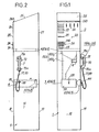
- the device is in the form of a hollow vertical terminal having a rectangular horizontal section.
- the height of the terminal as well as the locations of elements of the device accessible to a user are determined according to ergonomic criteria.
- the bollard is made up, in the lower part, of a monobloc post 1 in reinforced concrete or steel and, in the upper part, of a hollow monobloc box 2 also in resistant material, such as stainless steel.
- the post 1 is firmly fixed in the ground.
- the box 2 covers an upper part of the post 1 formed by a base 10.
- the box 2 has on a front face 20 different orifices and elements used by the user to establish and break a telephone communication.
- a telephone call can be prepaid by means of a magnetic or electronic card and by means of coins, either of these payment methods can be used by the user at the start or at any time at during a telephone call.
- the telephone set can establish outgoing communications and receive telephone calls for inbound communications establishments.
- the front face 20 of the box 2 has a slot 21 for inserting a card, slots 22 for inserting different coins, for example coins of 1FF, 2FF, 5FF and 10FF, and an openwork surface 23 behind which is disposed a audio unit for "hands-free" use comprising a microphone and a loudspeaker.
- the loudspeaker is used to broadcast a call tone calling a user.
- the front face 20 of the box are made suitable orifices crossed by twelve keys 240 of a dialing keyboard 24 and an orifice crossed by a reimbursement push button 25.
- the pressing of the push button 25 causes a breakdown in telephone communication , and the ejection of a card through the slot 21 or the reimbursement of coins in a reimbursement bowl 11 accessible in a front wall 12 of the post 1.
- the box 2 offers a top face 26 inclined downwards, from a rear face 27 of the box towards the front face 20, to form a desk with front edge 260.
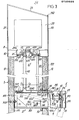
- the box 2 entirely covers a chassis 28 fixed on the top of the base 10.
- the chassis is typically formed of iron uprights and crosspieces, as shown diagrammatically in FIG. 3.
- the chassis 28 supports various mechanical and electromechanical means housed in the box and generally intended for establishing and breaking a telephone communication, such as the speaker audio unit and the microphone already mentioned, electromechanical reading means card, and electromechanical means for sorting and testing coins and storing them pending collection or reimbursement.
- a box, described hereinafter with reference to FIG. 10, contains electromechanical means, such as keys and contacts, of the dialing keyboard 24 and of the reimbursement button 25 and is integral with the box 2.
- the post 1 comprises a compartment 3 containing a removable cash box 4 and openable by a door and lock mechanism 5 in the front wall 12 of the post , a locking device 6 for securing the box 2 to the post 1 and detaching the box from the post 1, a telephone handset 7 with pedal 70 and an unlocking device 8 for detaching a removable microphone capsule 71m and a removable capsule of earpiece 71st of the handset 7.
- a hook 72 is provided to receive the handset 7.
- the box compartment 3 comprises a sheet metal frame 30 in which slides a drawer 31 receiving the box 4 and provided with the door and lock mechanism 5.
- the chassis 30 has a generally hollow parallelepiped shape, is open towards the top and the front, and extends between an internal face 130 of a rear wall 13 of the post 1 and a rectangular opening 120 formed in the front wall 12.
- a vertical rear side 301 of the chassis is fixed against the wall 13 by means of studs 302 each having one end with legs embedded in the post and another threaded end receiving a fixing nut.
- a front end of a bottom 303 of the chassis 30 rests on a horizontal side of the opening 120.
- the chassis 30 is provided with two pivoting hollow arms 304 extending horizontally when the drawer 31 is not pulled all the way forward as will be seen below.
- Rear ends of the arms 304 are articulated around horizontal pivots 305, parallel to the walls 12 and 13 and fixed at ends rear upper sides of the longitudinal vertical sides of the frame 30.
- the arms 304 slide two parallel arms 310 of the drawer 31 extending backwards.
- the arms 304 have vertical U-shaped sections with facing wings. Longitudinal sides of the arms 304 forming the souls of the U-sections are provided with horizontal slots 3040, forming slides, extending over horizontal ribs 306 of the frame 30.
- Idle rollers 311 with horizontal axes of rotation are mounted on the 'back of the arms 310 of the drawer and are intended to roll in the slots 3040 and on the ribs 306 when the arms 310 slide in the arms 304 in a horizontal position.
- two helical springs 307 with front strands integral with thrust washers 308 and with rear strands hooked to the pivots 305 slide coaxially behind the pivoting arms 304.
- the front of the sliding arms 310 protrude from a box receptacle 312 formed in the drawer 31.
- the receptacle 312 has a parallelepiped shape complementary to that of the box 4 and comprises two horizontal crosspieces 313 on which two lateral shoulders 40 are supported. of the box 4.
- the box 4 is provided with two lateral handles 41 for withdrawing upwards the box from the receptacle 312 when the drawer is pulled out.
- the door and lock mechanism 5 is fixed to a vertical front wall 314 of the drawer 31, forming an armored door of the compartment 3.
- a lock 50 of a known type is fixed through the armored door 314 along one side internal rear of which slide vertically and in opposite directions two pairs of bolts 51 cooperating with two strikes 52 fixed against an internal face 121 of the front wall 12 of the post and situated above and below the opening 120.
- the mechanism 5 also includes means for triggering an alarm before any attempt to break in the armored door 314 and the lock 50.
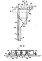
- the means for triggering an alarm comprise a hollow door 53 formed by a stamped sheet metal plate.
- the door 53 is fixed against the armored door 314 by means of deformable metal clips 54 contained in the door, as shown in Fig.4.
- Metal fasteners 54 are accordion-folded strips each having a front end 540 fixed to a vertical front internal face 530 of the storm door 53 by means of a threaded rod welded to the face 530 and receiving a nut, and a riveted rear end 541 or welded to armored door 314, to prevent the fasteners from being dismantled from the outside.
- the fasteners 54 press the storm door 53 parallel to the door 314, as shown in Fig.4.
- An electrical contact 55 housed in an upper side of the opening 120 cooperates with a horizontal support plane 56 integral with the storm door 53.
- the drawer 31 is contained in the compartment 3 and an external face 531 of the counter door 53 is coplanar with an external face 122 of the front wall 12 of the post by engagement of the bolts 51 in the strikes 52, the contact 55 is maintained in the closed state by the support plane 56.
- a malicious person seeks to access the lock 50 and the door 314, he must necessarily pull the door 53 forward and stretch the fasteners 54, as shown in Fig.5. Against the door 53 is thus moved away from the armored door 314, and the support surface 56 is distant from the contact 55 which passes to the open state to control an alarm transmission.
- the opening of the contact 55 controls an alarm device housed in the post 1, and / or causes a transmission of a particular signal to a telephone exchange connecting the telephone apparatus via alarm telephone transmission means and the telephone line.
- the alarm is broadcast in the form of a shrill sound signal by the loudspeaker already mentioned, and / or the central office alerting surveillance services, such as the police.
- an alarm is transmitted.
- the return to normal position of the storm door 53 against the door 314 is carried out economically by reforming the fasteners 54.
- the storm door 53 protects the lock 50 against the introduction of foreign bodies into it, and that a break in of the lock requires a long tool to pass through an inlet orifice. key 532 in the door 53.
- the opening of the box compartment 3 is carried out in two stages with a view to removing the box 14, and in a third subsequent step with a view to accessing the interior of the post 1 and the box 2.
- a key is introduced by a box lifter through the orifice 532.
- the key enters the lock 50 and is turned to release the latches 52 the bolts 51 which approach vertically.
- the springs 307 initially compressed, relax so that the stops 308 push forward, over a short length L 1 of a few centimeters, the rear ends of the arms 310 sliding in the horizontal arms 304. After the springs 307 relax, the front 53-314 of the drawer 31 protrudes from the front wall 12 of the post and provides a grip for the lifter to grasp the drawer and pull it outwards.
- the presence of the springs 307 makes it possible to verify that the compartment 3 is normally closed by the front 53-314 of the drawer flush with the face 122. In fact, if the drawer is not locked by the lock 50, the springs 307 push the drawer outwards, and the support surface 56 is released from the opening 120 and no longer ensures the closing of the door contact 55.
- the drawer 31 is pulled over a length L 2 until the box 4 is positioned in front of the face 122, on the outside, and can be withdrawn from the receptacle 312 by means of the handles 41
- a second electrical contact 57 fixed to the internal face 121 of the front wall 12 of the post is in the closed state when it is pressed by an upper face 42 of the box 4 located in the receptacle 312, drawer closed.
- An opening of the contact 57 is thus caused during the second step, and signals a withdrawal of the box.
- closing the compartment 3 by pushing and locking the drawer 31 without the latter containing a box, keeps the contact 57 open.
- the contact 57 in the open state signals an absence of a box in the compartment 3
- the contact 57 in the open state and the contact 55 in the closed state signal an absence of a box after closing the compartment.
- Contacts 55 and 57 are connected in series and, consequently, an opening of the contact 57 also produces a broadcasting of the audible alarm and / or a transmission of an alarm signal to the central office.
- the withdrawal of a box full of money by the lifter not followed by an insertion of a full box in the receptacle 312 and a closing of the compartment by pushing and locking the drawer is signaled.
- the electrical contacts 55 and 57 can be replaced by photoelectric cells or magnetic contacts.
- the telephone apparatus comprises a first so-called passive electronic equipment housed inside the post 1 making it possible to cut the power supply to the electromechanical means for reading the card and for sorting and testing coins as soon as the compartment is open to make it impossible to establish a telephone call.
- the central office is associated with a second so-called active electronic equipment which controls the broadcasting of the alarm by the loudspeaker and the transmission of the alarm to monitoring services only outside of specific predetermined periods. lifting a box.
- the two electronic devices will not be described, since they do not belong to the subject of the invention.
- the arms 310 slide forward in the pivoting arms 304 which are kept horizontal by virtue of the rollers 311 rolling and resting on the horizontal ribs 306 of the chassis 30.
- the drawer 31 can then be lowered by an angle a 3 of approximately 20 °, by pivoting the arms 304 around the horizontal pivots 305.
- This third step makes it possible to unlock the box 2 of the post 1 and to access the inside of the post 1, by means of the locking device 6 described below, placed in the post 1, between the base 10 and chassis 30 of the compartment.
- the base 10 has the shape of a parallelepipedal block fixed on upper edges of the walls of the post 1 and closing it. Noticeably in the center of the base 10 and parallel to the walls 12 and 13 of the post are formed three contiguous thin rectangular lights 1011, 101 2 and 101 3 in which are inserted respectively a coin reimbursement hopper 102 1 , a coin collecting hopper 102 2 and a locker to house printed circuit boards 102 3 .
- the hoppers 102 1 and 102 2 and the rack 102 3 are fixed in the upper part to the base 10, or have upper edges resting on the base, and have their major part emerging vertically under the base 10 above the chassis 30.
- the hoppers and the rack are made of sheet metal or plastic. Areas of the hoppers subjected to shocks and rubbing of the coins are preferably reinforced by metal plates.
- the hoppers 102 1 and 1022 are underlying electromechanical referral means disposed at the level of parts storage areas and included in the parts sorting and testing means fixed to the frame 28 in the box 2.
- a lower end of the hopper 102 1 converges downwards in the direction of the reimbursement bowl 11.
- a lower end of the hopper 102 2 converges downwards above a coin receiving slot 43 made in the box 4, when the latter this is contained in compartment 3 by locking the drawer 31.
- the collection hopper 102 2 is attached vertically to a conduit 103 through which pass electrical cables.
- These cables connect in particular the contacts 55 and 57, the telephone line, the microphone and the earpiece of the handset 7 and of the photoelectric or magnetic detectors for the passage of parts 104 1 , 104 2 and 104 3 to the electronic circuits implanted on the circuit boards. printed in the locker 102 3 .
- the locker 102 3 contains in particular electronic circuits relating to an audio circuit of the telephone apparatus, to the card reading means, to the means for sorting and testing the parts, to the dial pad 24 and to the passive equipment already cited.
- the three detectors 104 1 , 104 2 and 104 3 are aligned at three different levels along the vertical lower end 105 of the hopper 102 2 disposed above the box and only allowing the collection of a part to that time.
- the detectors help to validate the collection of each coin to be collected in view to indicate the collection of this to the active equipment associated with the central office through the telephone line. A passage of a part along a path different from the normal descent between the means for switching parts and the box, for example following a malicious uplift extraction of a part from the box, is thus detected.
- the base 10 also includes two lateral recesses 106, suitable for receiving complementary parts of the box 2, forming feet, in order to allow easy gripping of the rack when the latter is unlocked from the post, as will be seen below. Between the recesses 106 and of the ends of the openings I01 1 , 101 2 and 101 3 are provided two small lateral transverse mortises 107 to receive the major part of the locking device 6.
- the locking device 6 comprises two vertical rods 60 having lower ends 61 articulated to the pivoting arms 304, and upper ends 62 in the form of a sliding square in the mortises 107 of the base 10.
- the locking device 6 comprises two levers 63 each having two arms 630 and 631 on either side of an elbow 632 at approximately 120 °, mounted for rotation about a horizontal axis in the mortise 107
- a free end of the first arm 630 of each lever 63 braces the upper end 62 of the rod 60 and has a roller 633 sliding in an oblong horizontal slot 620 of the square end 62, extending parallel to the walls 12 and 13.
- a free end of the second arm 631 of each lever 63 is suitable for fitting into a small horizontal groove 290 underlying a lower part of the box 2, forming a tenon 29, sliding in the respective mortise 107 of the base 10 and complementary to the mortise.
- the pivoting arms 304 of the chassis 30 of the box compartment 3 are horizontal, the upper end 62 of the rod 60 is in the high position and is substantially flush with the horizontal upper surface of the base 10.
- the first arms 630 of the two levers 63 in each light 620 form an angle of about 60 ° having an apex directed upwards, and the second arms 631 are horizontal and hold the pins 29 in the mortises 107 so that the lower part of the box 2 surrounds the base 10 and that the box 2 is locked on the post 1.
- the drawer 31 is pulled forward so that the rollers 311 are no longer supported by the ribs 306 of the chassis 30 and abut against the front ends of the slots 3040 of the arms 304.
- the drawer 31 is then pivoted down around the pivots 305, for example using a lifter foot, until the lower surface of the box receptacle 312 abuts the lower front end of the chassis 3 in opening 120, as shown in phantom in Fig. 3.
- the drawer 31 has thus pivoted by the angle a 3 .
- the pivoting of the arms 304 drives the rod 60 vertically downwards, as shown in dashed lines in FIG. 3.
- the levers 63 in each mortise 107 rotate in the opposite direction by an angle of approximately 60 ° following the drive down of the rollers 633 by the upper end 62 of the rod 60.
- the second arms 631 rotate upwards as they approach the vertical in order to lift the box 2 by pushing against the studs 29 and release the free ends of the arms 631 from the grooves 290, which unlocks the box 2 from the post 1.
- the lower part of the box 2 is substantially flush with the base 10.
- the box 2 can then be removed from the frame 28 in order to access the devices supported by the frame 28, and the hand of the lifter can pass through the opening 120 of the pole to access a pulling ring for the device 8 for unlocking the microphone and earphone capsules of the handset 7.
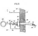
- the ends of the handset 7 have two threaded bosses 73m and 73e into which the microphone capsule 71m and the earphone capsule 71e are screwed respectively.
- Under threaded sections of cylindrical parts of the capsules 71e and 71m are provided annular grooves 74e and 74m which are arranged under the bosses 73m and 73e and in a internal cavity 75 of the combina 7, when the capsules are fully screwed into the bosses.
- the grooves 74e and 74m of the capsules cooperate with a flat and rectangular locking frame 80 of the device 8 slidably mounted between slides 76 preformed in the cavity 75 and perpendicular to the axes of the capsules and bosses.
- a flat and rectangular locking frame 80 of the device 8 slidably mounted between slides 76 preformed in the cavity 75 and perpendicular to the axes of the capsules and bosses.
- short flat sides 81m and 81e of the frames 80, forming bolts are engaged in the grooves 74m and 74e respectively thanks to two helical springs 82 vertically surrounding the longitudinal sides of the frame 8, sliding in the slides 76.
- a resistant flexible metal cord 77 which protects six conductive wires 770 for connecting the microphone, the earpiece and a relay contact controlled by the pedal 70 to the audio circuit of the telephone set.
- One end of the cord 77 is fixed to the handset by a stop ring 780 secured to a branch of a U-shaped bracket 78 fixed in the cavity 75, under the boss 73m.
- Another branch of the stirrup 78 is provided with a stop ring 781 with a sheath 830 with a traction cable 83 having a first end 831 fixed to the bolt 81m.
- the cable 83 is positioned in the center of the cord 77 and is surrounded by the conducting wires 770.
- the traction cable 83 contributes to strengthening the telephone cord 77 to better resist attempts to tear off the handset 7.
- a second end of the protective cord 77 passes through a sleeve 140 fixed in a lateral vertical wall 14 of the post 1, by means of an external collar 141 and an internal nut 142 bracing the wall 14.
- the second end of the cord 77 is fixed inside the post 1 by means of a stop ring 143 integral with the sleeve 140.
- the nut 142 also makes it possible to press a U-shaped stirrup 144 against an internal face 145 of the wall 14.
- the stirrup 144 has two horizontal branches with ends folded vertically upwards 146 and 147.
- the vertical end of the branch 146 supports a stop ring 148 for a second end of the sheath 830 of the traction cable 83 which comes out of the stop ring 143 together with the conductive wires 770 entering the vertical duct 103 under next to the base 10.
- a second end 832 of the traction cable 83 leaving the ring 148 is fixed to a ring 833.
- the box compartment 3 is opened, as described above, by pulling the drawer, so that a hand of the repairer can pass between the wall 12 of the post 1 and the armored door 314, under the drawer 31 and through the opening 120 (Fig.3), and catch the ring 833.
- the ring 833 is pulled in order to tow the cable 83 which slides in the sheath 830 , over a length L 4 greater than the depth of the annular grooves 74m and 74e, as shown in FIGS. 7 and 8.
- the frame 80 slides in the slides 76 in the direction of the boss 73e towards the boss 73m in order to release the bolts 81m and 8le gorges 74m and 74e respectively, as shown in phantom in Fig. 8.
- the traction exerted on the cable 83 against the restoring force exerted by the springs 82 is maintained by hooking the ring 833 to the second branch 147 of the stirrup 144, forming a hook.
- the capsules 71m and 71e can be unscrewed from the bosses 73m and 73e and replaced by other capsules which will again be joined to the handset by unhooking the ring 833 from the hook 147, the bolts 81m and 8 engaging in the 74m and 74th grooves of the new capsules thanks to the relaxation of the springs 82.
- the detachment of the ring 833 from the hook after the removal of the capsules 71m and 7le does not prevent the screwing of new capsules.
- the capsules 71m and 7le have lower ends terminated in conical points 78m and 78e, underlying the gorges 74m and 74e.
- the mechanism of the dial pad 24 is fixed to the front wall 20, inside the box.
- the push button for reimbursement and end of communication 25 as well as the contacts that it controls, is arranged in the same way and in the same mode as the keys and contacts of the keyboard mechanism 24.
- the keyboard mechanism is enclosed in a protective case 241 fixed against the wall 20 by means of a perforated counter plate 242, forming a grid, by means of bolts 243 invisible from the outside.
- the grid 242 forms an integral part of the box 2 and can be attached to the inside thereof by welding.
- Each key 240 has a horizontal T-shaped section, the wings of which form a prismatic block 244, for example square, which fits into a complementary hole 245 made in the wall 20 of the box, and whose leg 246 slidably crosses a hole 247 of the counterplate 242.
- the extraction of the keys 240 from the outside of the box is prevented by means of pins 248 passing through the legs 246 of the keys and sliding in suitable slots of housings 249 in the housing 241.
- the housings 249 each contain in a known manner, a key return spring and associated contacts.
- the reimbursement button 25 has a shape analogous to the keys 240 and is also tear-off from the box thanks to a mounting with a pin. 1 ..
- the invention has been described above with reference to a public telephone apparatus, most of the essential devices and mechanisms belonging to the object of the invention, such as the translatable and pivotable drawer 31, the door mechanism and lock 5 of the coin box compartment 3 and the locking device 6 of the box to the post, can be adapted to any device dispensing prepaid products or services.
- the dispensing device includes a keypad, it can have the characteristics mentioned above with reference to Fig. 10.
Landscapes
- Physics & Mathematics (AREA)
- General Physics & Mathematics (AREA)
- Control Of Vending Devices And Auxiliary Devices For Vending Devices (AREA)
- Telephone Set Structure (AREA)
- Cosmetics (AREA)
- Prepayment Telephone Systems (AREA)
- Supports Or Holders For Household Use (AREA)
Applications Claiming Priority (2)
| Application Number | Priority Date | Filing Date | Title |
|---|---|---|---|
| FR8417979 | 1984-11-26 | ||
| FR8417979A FR2573892B1 (fr) | 1984-11-26 | 1984-11-26 | Appareil distributeur de produits ou de services a prepaiement |
Publications (2)
| Publication Number | Publication Date |
|---|---|
| EP0189686A2 true EP0189686A2 (de) | 1986-08-06 |
| EP0189686A3 EP0189686A3 (de) | 1986-10-15 |
Family
ID=9309936
Family Applications (1)
| Application Number | Title | Priority Date | Filing Date |
|---|---|---|---|
| EP85402292A Ceased EP0189686A3 (de) | 1984-11-26 | 1985-11-25 | Vorrichtung zur Leistung von Diensten oder zur Abgabe von Waren gegen Vorauszahlung |
Country Status (5)
| Country | Link |
|---|---|
| US (1) | US4731819A (de) |
| EP (1) | EP0189686A3 (de) |
| CA (1) | CA1244169A (de) |
| FR (1) | FR2573892B1 (de) |
| WO (1) | WO1990005966A1 (de) |
Families Citing this family (10)
| Publication number | Priority date | Publication date | Assignee | Title |
|---|---|---|---|---|
| US4953374A (en) * | 1986-12-22 | 1990-09-04 | Wiebe Jacob R | Secure locking mechanism |
| ES2014071A6 (es) * | 1989-04-28 | 1990-06-16 | Telefonica Nacional Espana Co | Telefono publico modular para exteriores. |
| US5315654A (en) * | 1992-12-02 | 1994-05-24 | Kraft Carroll K | Armored telephone line protective system |
| US6061447A (en) * | 1995-02-13 | 2000-05-09 | N&T Systems Of Puerto Rico, Inc. | Protection device for telephone line and interface |
| US5930355A (en) * | 1995-02-13 | 1999-07-27 | Economic Development Bank For Puerto Rico | Protection device for telephone line and interface |
| GB2335065A (en) * | 1998-03-02 | 1999-09-08 | Alberice Meters Limited | A coin metering device |
| US6175752B1 (en) | 1998-04-30 | 2001-01-16 | Therasense, Inc. | Analyte monitoring device and methods of use |
| US9028305B2 (en) * | 2006-07-10 | 2015-05-12 | Coin Acceptors, Inc. | Coin changer with coin storage cassette having illumination and audible and visual feedback signals |
| FR2952745B1 (fr) * | 2009-11-13 | 2011-12-16 | Parkeon | Terminal de paiement en deux parties comportant un dispositif d'assemblage |
| AR113952A1 (es) * | 2018-01-03 | 2020-07-01 | Tecnologia Bancaria Sa | Dispositivo para anclar y proteger terminales de autoservicio y cajas en general |
Family Cites Families (19)
| Publication number | Priority date | Publication date | Assignee | Title |
|---|---|---|---|---|
| US2734764A (en) * | 1956-02-14 | Latch for a trunk lid | ||
| CH249257A (de) * | 1946-05-04 | 1947-06-15 | Siemens Ag Albis | Vorrichtung an Verschlussorganen zum Verhindern unbefugter Eingriffe. |
| US3056544A (en) * | 1960-06-06 | 1962-10-02 | Nautec Corp | Parking meter locking means |
| GB995220A (en) * | 1963-07-02 | 1965-06-16 | Scheidt & Bachmann Gmbh | Security arrangement for coin free mechanisms |
| US3317674A (en) * | 1963-11-18 | 1967-05-02 | Benner Nawman Inc | Pay telephone station |
| US3391256A (en) * | 1963-11-18 | 1968-07-02 | Benner Nawman Inc | Cover guard for pay telephone station |
| US3260338A (en) * | 1964-08-13 | 1966-07-12 | Teletek Inc | Switch closing coin escrow vanes |
| DE6752091U (de) * | 1968-08-22 | 1970-01-29 | Rega Gmbh & Co Kg | Automatengehaeuse fuer verkaufsautomaten |
| GB1310567A (en) * | 1970-09-04 | 1973-03-21 | Ass Automation Ltd | Coin collecting apparatus |
| DE7208883U (de) * | 1972-03-08 | 1973-08-23 | Krone Gmbh | Verdrehungssicherungsvorrichtung fuer fernsprechapparat-schraubkappen |
| CH568626A5 (en) * | 1974-03-01 | 1975-10-31 | Landis & Gyr Ag | Burglar-proof connection for coin receiving appts. - has two inner toggle linkages holding upper and lower housing |
| CH627600A5 (de) * | 1977-10-06 | 1982-01-15 | Sodeco Compteurs De Geneve | Muenzfernsprecher. |
| US4151380A (en) * | 1978-06-02 | 1979-04-24 | Gladwin, Inc. | Post mounted public telephone |
| DE2936504A1 (de) * | 1979-09-10 | 1981-03-26 | Siemens AG, 1000 Berlin und 8000 München | Selbstbedienungsgeraet mit muenzkassiereinrichtung |
| US4244304A (en) * | 1979-11-06 | 1981-01-13 | Read Ronald H | Security box and mounting plate |
| GB2120723A (en) * | 1982-05-28 | 1983-12-07 | Gen Electric Co Plc | Housing for coin-collecting apparatus |
| US4462317A (en) * | 1982-09-29 | 1984-07-31 | Lloyd Franko | Lock boxes |
| US4577563A (en) * | 1984-07-11 | 1986-03-25 | Sidler Karl J | Safekeeping box assembly |
| US4645876A (en) * | 1985-02-11 | 1987-02-24 | Burd, Bartz & Gutenkauf | Pay telephone |
-
1984
- 1984-11-26 FR FR8417979A patent/FR2573892B1/fr not_active Expired
-
1985
- 1985-11-22 CA CA000496000A patent/CA1244169A/fr not_active Expired
- 1985-11-25 WO PCT/FR1985/000333 patent/WO1990005966A1/fr not_active Ceased
- 1985-11-25 EP EP85402292A patent/EP0189686A3/de not_active Ceased
- 1985-11-25 US US06/893,292 patent/US4731819A/en not_active Expired - Fee Related
Also Published As
| Publication number | Publication date |
|---|---|
| WO1990005966A1 (fr) | 1990-05-31 |
| US4731819A (en) | 1988-03-15 |
| EP0189686A3 (de) | 1986-10-15 |
| FR2573892B1 (fr) | 1987-07-31 |
| FR2573892A1 (fr) | 1986-05-30 |
| CA1244169A (fr) | 1988-11-01 |
Similar Documents
| Publication | Publication Date | Title |
|---|---|---|
| EP0189686A2 (de) | Vorrichtung zur Leistung von Diensten oder zur Abgabe von Waren gegen Vorauszahlung | |
| WO2010067006A2 (fr) | Unite pour le chargement d'une batterie de dispositif electrique portable | |
| EP1340202A1 (de) | Gesichertes münzgerät | |
| EP0299899A1 (de) | Vorrichtung zum Verriegeln und Entriegeln von Notausgängen | |
| EP0315639B1 (de) | Aufbewahrungsfach, insbesondere für sporteinrichtungen | |
| US5148476A (en) | Telephone anti-theft device | |
| FR2911898A1 (fr) | Dispositif d'actionnement de pene et porte equipee dudit dispositif. | |
| WO2023126308A1 (fr) | Borne de collecte pour appareils électroniques | |
| FR2557189A1 (fr) | Installation de chambre forte pour banques | |
| FR2484518A1 (fr) | Dispositif de stockage et/ou de distribution d'argent | |
| EP0863292B1 (de) | Sperrvorrichtung für Bereiche mit Zugangskontrolle | |
| FR2701369A1 (fr) | Ensemble pour le stockage et/ou la fourniture contrôlée d'objets placés dans un présentoir. | |
| EP0022694B1 (de) | Kassette für einen Stapel von Blättern in einer Maschine zum Abgeben derselben | |
| FR2586126A1 (fr) | Distributeur automatique d'articles consommables concu pour etre pose sur un comptoir | |
| FR2732141A1 (fr) | Installation de consigne automatisee et procede de fonctionnement d'une telle installation | |
| FR2557330A1 (fr) | Appareil de reception et de distribution d'especes et appareil de manipulation d'especes | |
| FR2587134A1 (fr) | Compartiment caisse en particulier pour appareils a monnaie tels que les publiphones | |
| FR2858449A1 (fr) | Laverie a monnayeur | |
| FR2700933A1 (fr) | Casier de rangement et modules de casiers de rangement formant vestiaire par exemple. | |
| CH558867A (de) | Meuble a compartiments multiples comprenant un dispositif de securite. | |
| EP0064904B1 (de) | Schrank oder Gehäuse für steckbare elektrische Geräte | |
| FR2524283A1 (fr) | Dispositif de securite pour tiroir-caisse | |
| FR2740904A1 (fr) | Dispositif de montage de coupe-cirtuits electriques a cartouches-fusibles | |
| CH268339A (fr) | Appareil distributeur d'imprimés. | |
| FR2558205A1 (fr) | Sas de securite pour le depot d'objets |
Legal Events
| Date | Code | Title | Description |
|---|---|---|---|
| PUAI | Public reference made under article 153(3) epc to a published international application that has entered the european phase |
Free format text: ORIGINAL CODE: 0009012 |
|
| AK | Designated contracting states |
Kind code of ref document: A2 Designated state(s): BE CH DE GB IT LI NL SE |
|
| PUAL | Search report despatched |
Free format text: ORIGINAL CODE: 0009013 |
|
| AK | Designated contracting states |
Kind code of ref document: A3 Designated state(s): BE CH DE GB IT LI NL SE |
|
| 17P | Request for examination filed |
Effective date: 19870203 |
|
| 17Q | First examination report despatched |
Effective date: 19880930 |
|
| STAA | Information on the status of an ep patent application or granted ep patent |
Free format text: STATUS: THE APPLICATION HAS BEEN REFUSED |
|
| 18R | Application refused |
Effective date: 19891120 |