EP0189526B1 - Uni-directional/bi-directional gate valve - Google Patents
Uni-directional/bi-directional gate valve Download PDFInfo
- Publication number
- EP0189526B1 EP0189526B1 EP85113396A EP85113396A EP0189526B1 EP 0189526 B1 EP0189526 B1 EP 0189526B1 EP 85113396 A EP85113396 A EP 85113396A EP 85113396 A EP85113396 A EP 85113396A EP 0189526 B1 EP0189526 B1 EP 0189526B1
- Authority
- EP
- European Patent Office
- Prior art keywords
- gate
- valve
- flow passage
- chamber
- directional
- Prior art date
- Legal status (The legal status is an assumption and is not a legal conclusion. Google has not performed a legal analysis and makes no representation as to the accuracy of the status listed.)
- Expired - Lifetime
Links
Images


Classifications
-
- F—MECHANICAL ENGINEERING; LIGHTING; HEATING; WEAPONS; BLASTING
- F16—ENGINEERING ELEMENTS AND UNITS; GENERAL MEASURES FOR PRODUCING AND MAINTAINING EFFECTIVE FUNCTIONING OF MACHINES OR INSTALLATIONS; THERMAL INSULATION IN GENERAL
- F16K—VALVES; TAPS; COCKS; ACTUATING-FLOATS; DEVICES FOR VENTING OR AERATING
- F16K39/00—Devices for relieving the pressure on the sealing faces
- F16K39/04—Devices for relieving the pressure on the sealing faces for sliding valves
-
- F—MECHANICAL ENGINEERING; LIGHTING; HEATING; WEAPONS; BLASTING
- F16—ENGINEERING ELEMENTS AND UNITS; GENERAL MEASURES FOR PRODUCING AND MAINTAINING EFFECTIVE FUNCTIONING OF MACHINES OR INSTALLATIONS; THERMAL INSULATION IN GENERAL
- F16K—VALVES; TAPS; COCKS; ACTUATING-FLOATS; DEVICES FOR VENTING OR AERATING
- F16K3/00—Gate valves or sliding valves, i.e. cut-off apparatus with closing members having a sliding movement along the seat for opening and closing
- F16K3/02—Gate valves or sliding valves, i.e. cut-off apparatus with closing members having a sliding movement along the seat for opening and closing with flat sealing faces; Packings therefor
-
- Y—GENERAL TAGGING OF NEW TECHNOLOGICAL DEVELOPMENTS; GENERAL TAGGING OF CROSS-SECTIONAL TECHNOLOGIES SPANNING OVER SEVERAL SECTIONS OF THE IPC; TECHNICAL SUBJECTS COVERED BY FORMER USPC CROSS-REFERENCE ART COLLECTIONS [XRACs] AND DIGESTS
- Y10—TECHNICAL SUBJECTS COVERED BY FORMER USPC
- Y10T—TECHNICAL SUBJECTS COVERED BY FORMER US CLASSIFICATION
- Y10T137/00—Fluid handling
- Y10T137/0318—Processes
- Y10T137/0396—Involving pressure control
-
- Y—GENERAL TAGGING OF NEW TECHNOLOGICAL DEVELOPMENTS; GENERAL TAGGING OF CROSS-SECTIONAL TECHNOLOGIES SPANNING OVER SEVERAL SECTIONS OF THE IPC; TECHNICAL SUBJECTS COVERED BY FORMER USPC CROSS-REFERENCE ART COLLECTIONS [XRACs] AND DIGESTS
- Y10—TECHNICAL SUBJECTS COVERED BY FORMER USPC
- Y10T—TECHNICAL SUBJECTS COVERED BY FORMER US CLASSIFICATION
- Y10T137/00—Fluid handling
- Y10T137/8593—Systems
- Y10T137/86493—Multi-way valve unit
- Y10T137/86718—Dividing into parallel flow paths with recombining
- Y10T137/86759—Reciprocating
Definitions
- This invention relates to fluid control valves, and more particularly to gate valves for use where elevated temperatures and pressures are encountered.
- Bi-directional sealing gate valves of various designs are commonly used for controlling the flow of fluids in land based and subsea oil or gas wells and in pipelines of the petroleum and petrochemical industries.
- a line pressure buildup can occur due to fluid expansion that results if the temperature of the fluid increases. This increase in temperature typically occurs when, for example, valves at a surface (land or platform) wellhead are closed at nighttime and the ambient temperature rises the following day.Pressure buildup can be substantial with temperature increases of only 10-24°C (50-75 degrees Farenheit), but is much greater in the event of a fire which could raise the fluid temperature to 538-649°C (1000-1200 degrees Farenheit) or more.
- the invention is a fluid control valve as defined in the accompanying Claim 1 and a method of changing a sealing mode of the valve as defined in the accompanying Claim 17.
- the present invention comprises providing a port, groove, undercut or other pressure relief means in the gate of a gate valve so as to facilitate uni-directional sealing by placing the gate in one of two closed positions, and bi-directional sealing by placing the gate in the other closed position.
- the port or the like provides communication between the valve body and the flow passage extending from the adjacent gate face in which the port is located, and when in the other closed position the port is blocked and thus sealed off by the adjacent flow passage seat assembly.
- the port is located in the gate so that when the valve is in its normally closed condition the port is closed or blocked off, whereby the valve is in a bi-directional sealing mode, and when the gate is slightly backed off into another, but still closed, position the port is exposed to the flow passage, whereby the valve is in a uni-directional sealing mode.
- the position of the port is reversed, whereby when the valve is in its normally closed condition the port is open, and when the gate is backed off or otherwise moved into its other closed position the port is blocked.
- the invention can be embodied in all types of gate valves including, but not limited to, so-called fire-resistant gate valves, standard gate valves, and gate valves designed for subsea or other underwater use, both manually actuated as well as those with hydraulic, pneumatic or electrical actuators attached thereto.
- the invention can be embodied in gate valves wherein the flow passage through the gate is in either the lower portion of the gate as shown in the drawings, or in the upper portion of the gate (not shown).
- a gate valve in which the gate has one position in which the valve is fully open; a further position in which the valve is fully closed; and a third position in which pressure relief means in the gate permits fluid to flow directly through the gate from the high pressure side to the low pressure side to reduce the pressure on the high pressure side and thus reduce frictional resistance on the low pressure side of the gate.
- valve gate of this prior art has an up stream face and a downstream face; that each face has a relief valve containing flow path between said face and a common space between said faces so that when the gate valve is displaced to a setting in which it closes the main flow through the gate valve except for the fact that the two relief valve flow paths are then exposed in said main flow path, it will then be possible for pressure in the valve gate chamber to escape through the one of said relief flow passages that leads to the low pressure side of the valve gate.
- the valve in the relief flow passage that is facing the high pressure side of the valve gate choses due to said high pressure.
- Figure 1 is a fragmentary view, partially in central vertical section and partially in side elevation, of a fire-resistant type gate valve embodying the present invention in the form of a port in the valve gate which is shown in its normally closed position.
- Figure 2 is an enlarged fragmentary view of a portion of the valve of Figure 1, shoving the valve gate in a slightly backed off, yet still closed, position and the port blocked off.
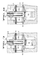
- Figures 3 and 4 are views similar to Figure 2, but illustrating a groove in the face of the valve gate as another embodiment of the invention.
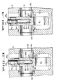
- Figures 5 and 6 are views somewhat like Figures 3 and 4, but illustrating another type of valve and a different location of the port in the valve gate.
- Figures 7 and 8 are views like Figures 5 and 6, but illustrating a groove in another location in the valve gate.
- a fire-resistant type gate valve 10 that includes a valve body 12 with a flow passage 14 and a valve gate chamber 16 intersecting the flow passage 14, a bonnet 18 releasably secured to the top of the valve body 12 by a plurality of circumferentially spaced threaded studs 20 and nuts 22, a valve gate 24 having a flow passage 26 through its lower portion, a non-rising type of valve stem 28 extending from the gate 24 through the bonnet 18, and a hand wheel 30 attached to the top of the stem 28 for rotating the stem and thereby raising and lowering the gate 24 between the gate's illustrated fully closed position and its open position (not shown) wherein the flow passages 14, 26 are coaxial.
- the stem 28 and the gate 24 are linked together by a lost motion connection comprising a nut 32 that threadedly engages the lower end of the stem, and a vertically elongated slot 34 in the upper end area of the gate and in which the nut 32 resides.
- annular spacer 36 of eutectic or fusible material that will melt when subjected to elevated temperature, such as if the valve were involved in a fire.
- elevated temperature such as if the valve were involved in a fire.
- the pressure in the valve body chamber 16 augmented by the axially directed force of a compressed helical spring 38 surrounding the stem 28 below the eutectic spacer 36, will cause the stem to move upwardly (outwardly) until a radial stop shoulder 40 on the stem above its lower threaded portion 28a comes to rest against an annular stop element 42 threaded into the lower face of the bonnet 18.
- annular seat elements or assemblies 50, 52 that reside in enlarged diameter portions of the valve's flow passage 14.
- the seat assemblies 50, 52 function to provide a fluid-tight seal between the valve gate 24 and the body 12, and in the illustrated embodiment the seat assembly 50 is located on the inlet side of the valve and seals against the opposed face 24a of the gate.
- Extending between the gate face 24a and a vertical bore 54 in the interior of the gate is a pressure relief port 56 that, when the gate 24 is in its illustrated normally closed position, provides communication between the flow passage inlet 14a and the bore 54, and thus into the valve gate chamber 16 via a lateral relief port 58 that extends from the bore 54 through the gate into the chamber 16.
- valve 10 in a uni-directional sealing mode, that is pressure on the inlet side cannot get past the outlet side seat element 52, whereas pressure entering the valve from the outlet side can escape through the relief port 56 into the inlet passage.
- valve 10 thereby provides a means to vent undesired pressure build-up both in the valve chamber 16 and, for example, a pipe line or other conduit (not shown) extending from the outlet passage 14b to the inlet side of another gate valve (not shown) such as would be found in a conventional oil or gas wellhead christmas tree.
- valve 10 When the hand wheel 30 is rotated sufficiently to take up the lost motion in the connection between the stem 28 and the gate 24, and further rotated to back off (raise) the gate 24 into its position shown in Figure 2, although the flow passage is still fully closed by the upper portion of the gate the pressure relief port 56 is blocked (closed off) by the inlet passage seat assembly 50. Therefore, with the gate 24 in this position any pressure build-up in the outlet flow passage 14b is prevented from entering the seat assembly 50 and the inlet flow passage 14a, and the valve 10 is in a bi-directional sealing mode. In this mode the valve 10 can be pressure-tested in either direction, a highly desirable advantage when the valve is employed in a wellhead christmas tree wherein pressure testing from the outlet side is standard operating procedure.
- valve gate 60 with a flow passage 61 has been substituted for the valve gate 24, but the rest of the valve elements remain the same as in the Figures 1 & 2 embodiment.
- Valve gate 60 has a groove 62 in its inlet face 60a that functions in similar manner to the port 56 in the valve gate 24, whereby in the gate's normally closed position ( Figure 3) the groove straddles the inlet passage seat assembly 50 to provide communication between the inlet passage 14a and the valve gate chamber 16, albeit directly rather than through the gate bore 54 and lateral relief port 58 as in the Figures 1 and 2 embodiment.
- the valve gate 60 provides both uni-directional and bi-directional sealing capability to the valve, and has the same advantages possessed by the embodiment of Figures 1 and 2.
- FIG. 5 and 6 provides for a fully automatic or self-induced uni-directional sealing mode when the valve is subjected to fire conditions. Under normal operating conditions the valve is bi-directional sealing and requires no special techniques, such as rotating the handwheel to back off the gate, to change to uni-directional sealing when a fire occurs.
- valve stem 28 there is no lost motion connection between the valve stem 28 and the gate 70, and a pressure relief port 72, located near the lower end of the gate's inlet face 70a, extends between the face 70a and the gate's flow passage 74.
- the valve can be identical to the fire-resistant type of Figure 1, or can be a standard gate valve without a eutectic element.
- valve gate 70 When the valve gate 70 is employed in a standard gate valve, the gate is shifted between its normally closed bi-directional sealing position (Fig. 5) and its backed off uni-directional sealing position (Fig. 6) by rotating the hand wheel or activating the valve actuator, depending upon how the valve is equipped.
- a valve gate 80 has a groove 82 in its inlet face 80a, such as near the upper end of the face 80a as illustrated, that straddles the inlet passage seat assembly 50 to provide communication between the inlet passage 14a and the gate chamber 16 when the gate 80 has been backed off from its normally closed bi-directional sealing position (Fig. 7) into its uni-directional sealing position (Fig. 8).
- the movement of the gate 70 is accomplished either automatically in a fire-resistant type valve such as 10 (Fig. 1) by melting of the eutectic element, or by hand wheel rotation, valve actuator activation or other means employed with a standard type gate valve. Accordingly, the gate 80 provides the same advantages as obtainable with the valve gate 70.
- each of the described embodiments of the present invention provides a relatively simple, inexpensive and virtually fool-proof means of insuring that high pressure build-ups will not occur in service, and also provides a means for pressure testing valves from either end.
Landscapes
- Engineering & Computer Science (AREA)
- General Engineering & Computer Science (AREA)
- Mechanical Engineering (AREA)
- Sliding Valves (AREA)
- Saccharide Compounds (AREA)
Applications Claiming Priority (2)
| Application Number | Priority Date | Filing Date | Title |
|---|---|---|---|
| US69695985A | 1985-01-31 | 1985-01-31 | |
| US696959 | 1985-01-31 |
Publications (3)
| Publication Number | Publication Date |
|---|---|
| EP0189526A2 EP0189526A2 (en) | 1986-08-06 |
| EP0189526A3 EP0189526A3 (en) | 1987-05-13 |
| EP0189526B1 true EP0189526B1 (en) | 1992-12-09 |
Family
ID=24799206
Family Applications (1)
| Application Number | Title | Priority Date | Filing Date |
|---|---|---|---|
| EP85113396A Expired - Lifetime EP0189526B1 (en) | 1985-01-31 | 1985-10-22 | Uni-directional/bi-directional gate valve |
Country Status (7)
| Country | Link |
|---|---|
| US (1) | US4711262A (pt) |
| EP (1) | EP0189526B1 (pt) |
| JP (1) | JPS61175375A (pt) |
| BR (1) | BR8600025A (pt) |
| CA (1) | CA1269652A (pt) |
| DE (1) | DE3586890D1 (pt) |
| NO (1) | NO169796C (pt) |
Families Citing this family (13)
| Publication number | Priority date | Publication date | Assignee | Title |
|---|---|---|---|---|
| US5332002A (en) * | 1993-09-21 | 1994-07-26 | Dril-Quip, Inc. | Gate valve |
| DE20115467U1 (de) * | 2001-09-20 | 2003-02-20 | Cameron Gmbh | Absperrvorrichtung |
| US20050156131A1 (en) * | 2004-01-16 | 2005-07-21 | Holliday David G. | Fire resistant valve assemblies |
| US7278444B2 (en) * | 2005-02-22 | 2007-10-09 | Mks Instruments, Inc. | Valve assembly having improved pump-down performance |
| NO328728B1 (no) | 2006-11-20 | 2010-05-03 | Aker Subsea As | Sluseventil for olje- og gass-produksjonssystemer |
| BRPI1008833A2 (pt) | 2009-02-04 | 2016-03-15 | Cameron Int Corp | luva de acionamento e mecanismo de vedação para válvula de comporta com haste não ascendente |
| NO331711B1 (no) | 2010-06-03 | 2012-03-05 | Statoil Petroleum As | Sluseventil, fremgangsmate for trykkregulering av returnert boreslam og/eller bronnstabilisering og anvendelser for en sluseventil. |
| US9353871B2 (en) * | 2013-12-31 | 2016-05-31 | Cameron International Corporation | Close only expansive gate valve |
| CN105422890A (zh) * | 2015-12-17 | 2016-03-23 | 上海诺特飞博燃烧设备有限公司 | 二步开关式闸阀 |
| CA3010334A1 (en) | 2016-01-04 | 2017-07-13 | Valveworks USA, Inc. | Gate valve with full-bore protective sleeve |
| BR102016012918A2 (pt) * | 2016-06-06 | 2017-12-19 | Fmc Technologies Do Brasil Ltda | Directional drawer type lock valve |
| US11047486B2 (en) | 2017-02-21 | 2021-06-29 | Stream-Flo Industries Ltd. | Expanding gate valve |
| WO2019019127A1 (zh) * | 2017-07-28 | 2019-01-31 | 江苏政轩石油机械股份有限公司 | 一种复合式低扭矩平板闸阀 |
Family Cites Families (16)
| Publication number | Priority date | Publication date | Assignee | Title |
|---|---|---|---|---|
| US3123090A (en) * | 1964-03-03 | Pressure relief gate valve | ||
| DE720081C (de) * | 1940-09-06 | 1942-04-23 | Eisenwerke Ag Deutsche | Absperrvorrichtung |
| US2664267A (en) * | 1950-06-29 | 1953-12-29 | Gen Controls Co | Hydraulically balanced gate valve structure |
| US2903006A (en) * | 1954-06-07 | 1959-09-08 | Scovill Manufacturing Co | Fire valves |
| FR2379741A1 (fr) * | 1977-02-02 | 1978-09-01 | Perolo Claude | Vanne a tiroir a passage integral pour l'utilisation avec des liquides a haute pression |
| DE2806737C2 (de) * | 1978-02-17 | 1984-06-28 | C.H. Zikesch GmbH Maschinen- und Apparatebau, 4100 Duisburg | Ventil, insbesondere für Hochdruckdampf |
| US4214600A (en) * | 1979-02-15 | 1980-07-29 | Cameron Iron Works, Inc. | Valve |
| US4354663A (en) * | 1980-03-03 | 1982-10-19 | U.S. Industries, Inc. | Valve construction for sand and slurry service |
| US4340203A (en) * | 1980-10-14 | 1982-07-20 | Deltrol Corp. | Three way slide valve with center return |
| US4373700A (en) * | 1981-02-25 | 1983-02-15 | Fmc Corporation | Metal seal for a gate valve stem |
| US4364544A (en) * | 1981-05-18 | 1982-12-21 | Daniel Industries, Inc. | Valve seat with sediment guard |
| DE3131943C2 (de) * | 1981-08-12 | 1983-09-01 | Combustion Engineering, Inc., 06095 Windsor, Conn. | Absperrschieber mit bei der Betätigung im Normalbetrieb axial feststehender Gewindespindel |
| US4433827A (en) * | 1981-12-04 | 1984-02-28 | Custom Oilfield Products, Inc. | High pressure shut-off valve |
| US4568062A (en) * | 1983-03-07 | 1986-02-04 | Fmc Corporation | Fire-resistant gate valve |
| US4540012A (en) * | 1983-04-18 | 1985-09-10 | Gray Tool Company | Temperature sensitive valve bonnet assembly |
| US4510960A (en) * | 1983-09-30 | 1985-04-16 | Fmc Corporation | Valve stem-to-bonnet backseat |
-
1985
- 1985-10-09 CA CA000492637A patent/CA1269652A/en not_active Expired - Lifetime
- 1985-10-22 EP EP85113396A patent/EP0189526B1/en not_active Expired - Lifetime
- 1985-10-22 DE DE8585113396T patent/DE3586890D1/de not_active Expired - Lifetime
- 1985-11-01 JP JP60244256A patent/JPS61175375A/ja active Pending
-
1986
- 1986-01-07 BR BR8600025A patent/BR8600025A/pt not_active IP Right Cessation
- 1986-01-30 NO NO860335A patent/NO169796C/no unknown
- 1986-03-03 US US06/837,317 patent/US4711262A/en not_active Expired - Lifetime
Also Published As
| Publication number | Publication date |
|---|---|
| CA1269652A (en) | 1990-05-29 |
| US4711262A (en) | 1987-12-08 |
| NO860335L (no) | 1986-08-01 |
| EP0189526A2 (en) | 1986-08-06 |
| EP0189526A3 (en) | 1987-05-13 |
| BR8600025A (pt) | 1986-09-23 |
| NO169796B (no) | 1992-04-27 |
| DE3586890D1 (de) | 1993-01-21 |
| NO169796C (no) | 1992-08-05 |
| JPS61175375A (ja) | 1986-08-07 |
Similar Documents
| Publication | Publication Date | Title |
|---|---|---|
| EP0189526B1 (en) | Uni-directional/bi-directional gate valve | |
| US4340088A (en) | Pressure balanced safety valve for wells and flow lines | |
| CA1294599C (en) | Modular hydraulic actuator | |
| US4434967A (en) | Valve self-relieving seats | |
| CA2403876C (en) | Internal gate valve for flow completion systems | |
| US4331315A (en) | Actuatable safety valve for wells and flowlines | |
| US4436279A (en) | Stem connection for gate valve | |
| US4452310A (en) | Metal-to-metal high/low pressure seal | |
| US4671312A (en) | Wireline cutting actuator and valve | |
| US5090661A (en) | Gate valve | |
| US4682757A (en) | Secondary backseat for gate valve | |
| US4749043A (en) | Subsurface safety valves and seals | |
| GB2253467A (en) | Gate valve with hydraulic actuator. | |
| US3887158A (en) | Blow out preventers | |
| EP0701079B1 (en) | Expanding gate valve | |
| US4540013A (en) | Fire responsive stem retention apparatus | |
| US4716969A (en) | Hydraulic valve actuating means for subsurface safety valve | |
| US4356996A (en) | High pressure globe and check valve | |
| US3050132A (en) | Fluid pressure operated shut-off valve for wells | |
| US3406712A (en) | Pressure operated snap acting valve | |
| US5109881A (en) | Temperature sensitive control valve | |
| EP0053983A1 (en) | Composite ball valve seal assembly | |
| US3042057A (en) | High and low pressure cut-off valve | |
| GB2266576A (en) | Selective double backseat for valve stems | |
| EP1451496B1 (en) | Control valve pressure bleed inspection port |
Legal Events
| Date | Code | Title | Description |
|---|---|---|---|
| PUAI | Public reference made under article 153(3) epc to a published international application that has entered the european phase |
Free format text: ORIGINAL CODE: 0009012 |
|
| AK | Designated contracting states |
Kind code of ref document: A2 Designated state(s): BE DE FR GB IT NL |
|
| PUAL | Search report despatched |
Free format text: ORIGINAL CODE: 0009013 |
|
| 17P | Request for examination filed |
Effective date: 19870304 |
|
| AK | Designated contracting states |
Kind code of ref document: A3 Designated state(s): BE DE FR GB IT NL |
|
| 17Q | First examination report despatched |
Effective date: 19881121 |
|
| GRAA | (expected) grant |
Free format text: ORIGINAL CODE: 0009210 |
|
| AK | Designated contracting states |
Kind code of ref document: B1 Designated state(s): BE DE FR GB IT NL |
|
| PG25 | Lapsed in a contracting state [announced via postgrant information from national office to epo] |
Ref country code: IT Free format text: LAPSE BECAUSE OF FAILURE TO SUBMIT A TRANSLATION OF THE DESCRIPTION OR TO PAY THE FEE WITHIN THE PRESCRIBED TIME-LIMIT;WARNING: LAPSES OF ITALIAN PATENTS WITH EFFECTIVE DATE BEFORE 2007 MAY HAVE OCCURRED AT ANY TIME BEFORE 2007. THE CORRECT EFFECTIVE DATE MAY BE DIFFERENT FROM THE ONE RECORDED. Effective date: 19921209 Ref country code: DE Effective date: 19921209 Ref country code: BE Effective date: 19921209 |
|
| REF | Corresponds to: |
Ref document number: 3586890 Country of ref document: DE Date of ref document: 19930121 |
|
| ET | Fr: translation filed | ||
| PLBE | No opposition filed within time limit |
Free format text: ORIGINAL CODE: 0009261 |
|
| STAA | Information on the status of an ep patent application or granted ep patent |
Free format text: STATUS: NO OPPOSITION FILED WITHIN TIME LIMIT |
|
| PGFP | Annual fee paid to national office [announced via postgrant information from national office to epo] |
Ref country code: NL Payment date: 19931031 Year of fee payment: 9 |
|
| 26N | No opposition filed | ||
| PG25 | Lapsed in a contracting state [announced via postgrant information from national office to epo] |
Ref country code: NL Effective date: 19950501 |
|
| NLV4 | Nl: lapsed or anulled due to non-payment of the annual fee | ||
| PGFP | Annual fee paid to national office [announced via postgrant information from national office to epo] |
Ref country code: GB Payment date: 19981001 Year of fee payment: 14 |
|
| PGFP | Annual fee paid to national office [announced via postgrant information from national office to epo] |
Ref country code: FR Payment date: 19981006 Year of fee payment: 14 |
|
| PG25 | Lapsed in a contracting state [announced via postgrant information from national office to epo] |
Ref country code: GB Free format text: LAPSE BECAUSE OF NON-PAYMENT OF DUE FEES Effective date: 19991022 |
|
| GBPC | Gb: european patent ceased through non-payment of renewal fee |
Effective date: 19991022 |
|
| PG25 | Lapsed in a contracting state [announced via postgrant information from national office to epo] |
Ref country code: FR Free format text: LAPSE BECAUSE OF NON-PAYMENT OF DUE FEES Effective date: 20000630 |
|
| REG | Reference to a national code |
Ref country code: FR Ref legal event code: ST |