EP0189497A1 - Arrangement for the insertion of at least one weft thread into looms - Google Patents
Arrangement for the insertion of at least one weft thread into looms Download PDFInfo
- Publication number
- EP0189497A1 EP0189497A1 EP85100856A EP85100856A EP0189497A1 EP 0189497 A1 EP0189497 A1 EP 0189497A1 EP 85100856 A EP85100856 A EP 85100856A EP 85100856 A EP85100856 A EP 85100856A EP 0189497 A1 EP0189497 A1 EP 0189497A1
- Authority
- EP
- European Patent Office
- Prior art keywords
- thread
- weft
- weft thread
- tensioning device
- arrangement according
- Prior art date
- Legal status (The legal status is an assumption and is not a legal conclusion. Google has not performed a legal analysis and makes no representation as to the accuracy of the status listed.)
- Granted
Links
Images


Classifications
-
- D—TEXTILES; PAPER
- D03—WEAVING
- D03D—WOVEN FABRICS; METHODS OF WEAVING; LOOMS
- D03D47/00—Looms in which bulk supply of weft does not pass through shed, e.g. shuttleless looms, gripper shuttle looms, dummy shuttle looms
- D03D47/34—Handling the weft between bulk storage and weft-inserting means
Landscapes
- Engineering & Computer Science (AREA)
- Textile Engineering (AREA)
- Looms (AREA)
Abstract
Die Anordnung dient dem Eintragen von mindestens einem Schussfaden für Webmaschinen und umfasst eine Schussfadenspannvorrichtung (I) der eine zweite Schussfadenspannvorrichtung (II) folgt, deren Fadenspannlänge gleich der Uebergabelänge (x) des Schussfadens (16) durch die Schussfadengeberdüse (35) an das Projektil (34) entspricht und die einen Teil des Schussfadens (16) mit einer Länge gleich der Uebergabelänge (x) zur Uebergabe an das Projektil (34) freigibt bevor die erste Spannvorrichtung (I) den Schussfaden (16) zum Eintragen freigibt und die einen gleichlangen Teil des Schussfadens (16) nach der Eintragung zurückzieht. Die Anordnung verhindert dass eine Schussfadenende (16") nicht von der Geberdüse (32) an das Projektil (34) übergeben und der Schussfaden (16) daher nicht eingetragen wird.The arrangement serves to insert at least one weft thread for weaving machines and comprises a weft thread tensioning device (I) which is followed by a second weft thread tensioning device (II), the thread tension length of which corresponds to the transfer length (x) of the weft thread (16) through the weft threading nozzle (35) to the projectile ( 34) and which releases a part of the weft thread (16) with a length equal to the transfer length (x) for transfer to the projectile (34) before the first tensioning device (I) releases the weft thread (16) for insertion and the one part of the same length of the weft thread (16) withdraws after the entry. The arrangement prevents a weft end (16 ") from being transferred from the donor nozzle (32) to the projectile (34) and the weft thread (16) therefore not being inserted.
Description
Die Erfindung betrifft eine Anordnung zum Eintragen von mindestens einem Schussfaden für Webmaschinen, insbespndere Greiferprojektil-Webmaschinen, mit einer ersten Schussfadenspannvorrichtung und.. einer Schussfadenübergabevorrichtung zum Halten des Schussfadens bis zu dessen Uebergabe an eine Schussfadeneintragsvorrichtung.The invention relates to an arrangement for inserting at least one weft thread for weaving machines, in particular rapier projectile weaving machines, with a first weft thread tensioning device and .. a weft thread transfer device for holding the weft thread until it is transferred to a weft thread insertion device.
Bei einer bekannten Vorrichtung dieser Art (EP-OS 090878; Fig. 5) wird der Fadenspanner der Spannvorrichtung mit verhältnismässig geringer Beschleunigung von der Anfangslage in eine Zwischenlage angehoben, derart, dass der Fadenspanner mit dem einzutragenden Schussfaden in Berührung bleibt, wenn dieser von der Geberdüse angezogen wird. Dadurch findet die Uebergabe des Schussfadens an das Projektil mit verhältnismässig geringer Geschwindigkeit statt, was die Zuverlässigkeit der Uebergabe erhöht. Daraufhin wird der Fadenspanner mit grosser Geschwindigkeit und frei vom Faden von der Zwischenlage in die Endlage angehoben.In a known device of this type (EP-OS 090878; Fig. 5), the thread tensioner of the tensioning device is raised from the initial position into an intermediate position with relatively little acceleration, such that the thread tensioner remains in contact with the weft thread to be inserted when it is removed from the Donor nozzle is tightened. As a result, the transfer of the weft thread to the projectile takes place at a relatively slow speed, which increases the reliability of the transfer. The thread tensioner is then lifted from the intermediate position into the end position at high speed and free of the thread.
Die Erfahrung hat nun gelehrt, dass es eigentlich erforderlich ist, dass der Fadenspanner in der kurzen Zwischenphase zwischen den beiden Bewegungsabläufen verharrt, bis das Schussfadenende vom Projektil erfasst und dieses abschussbereit ist. Weil jedoch der Fadenspanner vor dem Zeitpunkt des Abschusses des Projektils in Richtung Endstellung in Bewegung sein muss damit der Schussfaden nicht bei der nachfolgenden plötzlichen Eintragsbewegung durch den ReibungwiderstandExperience has now shown that it is actually necessary for the thread tensioner to remain in the short intermediate phase between the two motion sequences until the end of the weft is caught by the projectile and the projectile is ready to fire. However, because the thread tensioner is moving towards the end position before the projectile is fired the weft does not have to be during the subsequent sudden entry movement due to the frictional resistance
an den Umlenkstellen des Fadenspanners zerrissen wird, staut sich der Schussfaden vor dem Projektil auf und es kann geschehen, dass das Schussfadenende sich vor dem vollständigen Schliessen des Projektils schräg zu diesem stellt und nicht vom Projektil übernommen wird und ein sogenannter Verlierer entsteht oder aber, dass das Fadenende zwischen der Schlagnase der Abschussvorrichtung und dem Projektil gelangt und beim Abschiessen gequetscht wird.is torn at the deflection points of the thread tensioner, the weft thread builds up in front of the projectile and it can happen that the weft thread end is inclined to the projectile before it is completely closed and is not taken over by the projectile and a so-called loser arises or that the end of the thread gets between the knocking nose of the launcher and the projectile and is squeezed when firing.
Der Erfindung liegt die Aufgabe zugrunde eine Schussfadenspannvorrichtung der eingangs definierten Art zu schaffen, wobei diese nachteiligcnErscheinungen nicht auftreten können. Diese Aufgabe wird gemäss der Erfindung durch die im Kennzeichen des Anspruchs 1 angegebenen Merkmale gelöst. Die Unteransprüche betreffen vorteilhafte Weiterbildungen.The invention has for its object to provide a weft thread tensioning device of the type defined in the introduction, whereby these disadvantageous phenomena cannot occur. This object is achieved according to the invention by the features specified in the characterizing part of
Einige Ausführungsbeispiele des Erfindungsgegenstandes sind nachfolgend anhand der Zeichnungen beschrieben. Es ist:
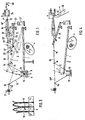
- Fig. l die Anordnung zum Eintragen von Schussfäden gemäss der Erfindung in schematischer Darstellung;
- Fig. 2 einen Teil der Anordnung;
- Fig. 3 einige Schussfaden-Halteelemente;
- Fig. 4 Die Anordnung in der Lage nach dem Uebergeben des Schussfaden an das Projektil;
- Fig. 5 eine abgewandelte Ausführung der Halteelemente;
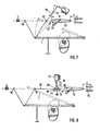
- Fig. 6,7 und 8 eine abgewandelte Ausführungsform;
- Fig. 9 eine Ausführungsform für Zweischuss- bzw. Misch-r wechselbetrieb.
- Figure l shows the arrangement for inserting weft threads according to the invention in a schematic representation.
- 2 shows a part of the arrangement;
- 3 shows some weft holding elements;
- 4 shows the arrangement in the position after transferring the weft thread to the projectile;
- 5 shows a modified embodiment of the holding elements;
- Figures 6,7 and 8 a modified embodiment;
- 9 shows an embodiment for two-shot or mixed-r alternating operation.
Fig. 1 zeigt eine Anordnung zum musterprogrammgemässen Eintragen von acht Schussfäden in Wechselbetrieb, die aus einer Schussfadenspannvorrichtung I und einer Schussfadenspannvorrichtung II besteht. Die Spannvorrichtung I ist nachfolgend anhand von Fig. 2 beschrieben.1 shows an arrangement for inserting eight weft threads in alternating operation according to the sample program, which consists of a weft thread tensioning device I and a weft thread tensioning device II. The tensioning device I is described below with reference to FIG. 2.
Die Spannvorrichtung I weist einen Fadenspanner 1 in Form eines Bügels auf, der um eine Achse 2 drehbar ist. Der Fadenspanner 1 ist mit einer Rolle 3 an einer Steuerscheibe 4 geführt, die von der Hauptwelle der Webmaschine angetrieben ist. Ein Querbalken 5 des Fadenspanners 1 schwingt im Maschinenrhythmus quer zu einer Schar 6 von Schussfäden, die je einer (nicht gezeichneten) Vorratsspule .entstammen. Der Querbalken ist mit acht Fadenmulden versehen. Vor jeder Fadenmulde 7 befinden sich beidseits des Querbalkens 5 zwei Träger 8 bzw. 9 mit einem (deutlichkeitshalber hier nicht gezeichneten) Halteelement für-jeden Schussfaden. Weiterhin befindet sich beidseits des Querbalkens 5 ein Träger 11 bzw. 12 mit je acht Fadenoesen 13 bzw. 14. Für jeden Schussfaden ist eine Fadenbremse vorgesehen, wovon nur eine, die für einen Schussfaden 16, eingezeichnet und mit der Bezugsnummer 17 versehen ist. Nach Durchlaufen der Spannvorrichtung I gelangt die Schussfadenschar 6 in die Schussfadenspannvorrichtung II. Fig. 3 zeigt drei der acht Halteelemente, die auf dem Träger 8 befestigt sind , Jedes Halteelement 18 besteht aus zwei Lamellen 18' und 18 die durch ihre Feder einen vom Fadenspanner 1 ausgelenkten Schussfaden halten können. Die auf dem Träger 9 befestigten Halteelemente sind in Fig. 1 mit 19 bezeichnet.The tensioning device I has a
In Fig. 1 sind beide Spannvorrichtungen I und II schematisch dargestellt. Die Schussfadenspannvorrichtung II weist acht Fadenspanner 25 in Form eines Hebels mit einer Fadenmulde 26 auf, der um eine Achse 27 drehbar ist. Beidseits jeder Fadenmulde befindet sich eine Fadenöse 28 bzw. 29, die auf Trägern 30 bzw. 31 befestigt sind. Die Schussfadenschar 6 durchläuft von der Spannvorrichtung I kommend die Spannvorrichtung II und eine Geberdüse 32, deren Mündung 33 vor einem Greiferprojektil in Abschussstellung endet. Vom Projektil ist nur die Fadenklemme 34 gezeichnet. Die Geberdüse 32 wird über eine Leitung 35 mit Druckluft gespeist. Jeder Schussfaden, z.B. wiederum der Schussfaden 16, durchläuft die Oese 28, die Fadenmulde 26 im betreffenden Fadenspanner, die Oese 29 und einen der acht Schussfadenführungskanäle in der Geberdüse 32. Jeder Fadenspanner 25 wird gemäss Gewebemusterprogramm von einem zugehörigen Motor 37 synchron mit dem Fadenspanner 1 betättigt, so dass der ausgewählte Fadenspanner 25 zwischen einer ausgelenkten Lage 25' und einer Freigabelage 25" auf-und abbewegt wird.In Fig. 1, both clamping devices I and II are shown schematically. The weft thread tensioning device II has eight
Die in Fig. 1 gezeichnete Lage ist für die folgende Erklärung der Arbeitsweise der Anordnung als Ausgangslage genommen. Alle Schussfäden sind durch die Fadenspanner l und 25 ausgelenkt. Die vom Querbalken 5 ausgelenkten Schussfäden werden von den Halteelementen 18 und 19 in dieser Lage festgehalten. Alle Schussfäden in beiden Spannvorrichtungen I und II sind durch das Ziehen der durch die Geberdüse 32 strömende Druckluft gespannt. Die Fadenklemme 34 ist geöffnet. Beim Eintragen des ausgewählten Schussfadens - es wird hier wiederum als Beispiel der Schussfaden 16 betrachtet - schwingt zunächst der zugehörige Fadenspanner 25 im Uhrzeigersinn, so dass sich der Schussfaden frei durch die Zugkraft der Düse 32 in die Lage 16' strecken kann. Die Düse 32 bläst dabei das Ende 16" des Schussfadens in die Fadenklemme 34 des Projektils. Hierbei rückt der Schussfaden über eine Länge x vorwärts. Diese Länge wird hier als Uebergabelänge bezeichnet. Die Fadenklemme 34 wird nun geschlossen. Die Lage ist wie in Fig. 4 gezeigt.The position shown in Fig. 1 is taken as the starting point for the following explanation of the operation of the arrangement. All weft threads are deflected by
Bei Anfang der Freigabebewegung des Fadenspanners 25 wurde gleichzeitig der Fadenspanner 1 der Fadenspannvorrichtung I von der Steuerscheibe 4 angehoben. Die Halteelemente 18 und 19 halten jedoch den Faden 16 in der ausgelenkten Lage. Wenn die Uebergabe des Schussfadens an die Fadenklemme 34 des Projektils beendet ist, hat der Fadenspanner 1 die Lage l' erreicht . In diesem Zeitpunkt wird das Projektil durch einen Abschussmechanismus 38 in das Webfach wgescfiossen. Dabei wird der Schussfaden 16 aus den Halteelementen 18 und 19 gezogen. Vor dem Abschuss des Projektils wurde die Fadenbremse 17 geöffnet, so dass der Schussfaden mit der erforderlichen Eintragslänge von der Vorratsspule abgezogen und in das Webfach eingetragen wird. Während der Anfangsphase des Abschusses bewegt die Steuerscheibe 4 den Fadenspanner 1 kontinuierlich weiter aufwärts, so dass der Schussfaden sich frei unter dem Einfluss der Zugkraft des Projektils 32 in die Lage 16'" strecken kann. Die nicht einzutragenden Schussfäden bleiben in ihren Halteelementen geklemmt. Ebenso bleiben die entsprechenden Fadenspanner der Fadenspannvorrichtungen II der nicht einzutragenden Schussfäden in ihrer ausgelenkten Stellung. Nachdem das Projektil den Schussfaden durch das Webfach gezogen hat, wird es im Fangwerk abgebremst und daraufhin von einem Rückschieber etwas zurückgeschoben bis es die Ausstossstellung erreicht hat. Gleichzeitig wird der Fadenspanner 1 durch die Steuerscheibe 4 gesenkt, so dass der Schussfaden gestreckt bleibt. Eine Randfadenklemme auf beiden Seiten des Webfaches übernimmt den Schussfaden. Der Schussfaden wird schusseitig von einer Schere 39 durchgeschnitten und fangseitig vom Projektil durch Oeffnen der Fadenklemme 34 freigegeben. Der Faden wird vom Riet angeschlagen. Der Schussfaden wird vom sich weiter senkenden Fadenspanner 1 und zusätzlich vom sich ebenfalls senkenden Fadenspanner 25 weiter ausgelenkt bis sein Ende innerhalb der Mündung 33 der Düse 32 liegt. Während sich der Fadenspanner 1 mit dem Schussfaden zur Tieflage bewegt, wird der Faden zwischen den Halteelementen 18 und 19 festgeklemmt. Eine Transportvorrichtung nimmt das aus dem Fangwerk ausgestossene Projektil auf und befördert es ausserhalb des Webfaches an die Abschussstelle zurück. Das Projektil wird vom Projektilöffner geöffnet und gleichzeitig von einem Projektilheber vor die Düse 32 schwenkt, so dass es bereit ist zum Aüfnehmen des nächsten Schussfadens. Die Lage ist dann wiederum wie in Fig. 1.At the beginning of the release movement of the
Fig. 5 zeigt ein Ausführungsbeispiel, wobei die Halteelemente 40 und 41 für die Schussfäden bis zu der Höhe der gestreckten Schussfäden 42' heranreichen oder gar etwas darüber hinaus. Solche lange Halteelemente bremsen den Schussfaden praktisch während seiner ganzen Steckbewegung. Durch die vom Schussfaden erfahrene Reibung geht das Strecken des Schussfadens beim Eintragungsvorgang gleichmässig und nicht ruckartig vor sich, so dass er nicht übermässig belastet wird.FIG. 5 shows an exemplary embodiment, the holding
Bei dem Ausführungsbeispiel nach Fig. 6 besteht die Anordmit einem Fadenspanner 44 nung aus einer ersten Spannvorrichtung III mit einem Fadenspanner 44 und einer zweiten Spannvorrichtung IV. Die Spannvorrichtung IV besitzt für jeden Schussfaden einen Fadenspanner 45 in der Form ei-Doppelhebels, nesvaer um einen Fixpunkt 46 drehbar ist und an seinem freien Ende mit einer Fadenoese 47 für den Schussfaden versehen ist. Das andere Ende des Fadenspanners 45 ist mit einer Stellstange 48 eines Stellmotors 49 verbunden. Die erste Spannvorrichtung III und die Spannvorrichtung IV haben somit die Fadenoesen 47 gemeinsam. Die Anordnung arbeitet in der Weise, dass die Uebergabe des einzutragenden Schussfadens 50 an die Fadenklemme des Projektils stattfindet durch eine Drehung im Gegenuhrzeigersinn des Fadenspanners 45, so dass sein Teil 45' den Schussfaden mittels der Fadenoese 47 von der Lage 47' nach rechts in die Lage 47" verlegt. Es findet somit eine Teilstreckung bzw. Vorwärtsbewegung des Schussfadens statt, so dass die Fadenlänge x zum Uebergeben an das Projektil freigegeben wird. Nach dem Eintragen werden beim Rückschieben des Projektils bzw. nach dem schusseitigen Abschneiden des Schussfadens die Spannvorrichtungen III und IV in ihre Auslenkstellungen zurückgeschwenkt.In the embodiment according to Fig . 6, the arrangement with a thread tensioner 44 consists of a first tensioning device III with a thread tensioner 44 and a second tensioning device IV. For each weft thread, the tensioning device IV has a
Bei dem Ausführungsbeispiel nach Fig. 7 ist ein Drehpunkt55 eines Fadenspanners 56 einer Spannvorrichtung V so gewählt, dass die Fadenoese 57 des Fadenspanners am Ende der Freigabebewegung der Spannvorrichtung in einerlLage 57' unterhalb einer Geberdüse 58 liegen. Dies hat den Vorteil, dass die Unterseite der Eingänge 59 der Schussfadenkanäle in der Geberdüse 58 Fadenführer bilden.In the exemplary embodiment according to FIG. 7, a
Beim Ausführungsbeispiel nach Fig. 8 weist eine Spannvorrichtung VI für jeden Schussfaden einerseits drei Umlenkkörper 65, 66 und 67 unterhalb eines Schussfadens 68 auf und anderseits zwei Umelenkkörper 69 und 70, die an einer Stellstange 71 eines Stellmotors 72 befestigt sind. In der Ausgangslage befinden sich die Umlenkkörper 69 und 70 jeweils zwischen den Umlenkkörpern 65,66 bzw. 66, 67, so dass zwei Schlaufen 73 und 74 gebildet sind und das Schussfadenende 68 in der Mündung einer Geberdüse 75 liegt. Zum Uebergeben des Schussfadens an eine Fadenklammer 76 des Greiferprojektils wird die Stellstange 71 aus der Tieflage 71' vom Stellmotor 72 angehoben, so dass die beiden Schlaufen 73 und 74 sich strecken und gesamt die Uebergabelähge x an das Projektil ergeben. Beim Zurückschieben des Projektils bzw. nach schusseitigem Abschneiden des Schussfadens werden beide Spannvorrichtungen in ihre Auslenkstellung zurückgeschwenkt.In the exemplary embodiment according to FIG. 8, a tensioning device VI for each weft thread has on the one hand three deflecting
Fig. 9 zeigt ein Ausführungsbeispiel einer Anordnung zum Eintragen der Schussfäden im Zweischuss- bzw. Mischwechselbetrieb, wobei zwei Schussfäden abwechselnd bzw. abwechselnd nach einem bestimmten Musterproqramm eingetragen werden. Es ist für jeden Schussfaden 85 bzw. 86 eine Eintragsvorrichtung vorgesehen. Die Eintragsvorrichtung 87 für den Schussfaden 85 besteht aus einer Spannvorrichtung VII und einer Spannvorrichtung VIII. Die Eintragsvorrichtung 88 für den Schussfaden 86 besteht aus einer Spannvorrichtung IX und eine. Spannvorrichtung X. Beide Eintragsvorrichtungen 87 und 88 arbeiten abwechselnd bzw. musterprogrammgemäss jeweils wie vorher für die anderen Ausführungsformen beschrieben. Die Spannbewegungen der Schussfädenabschnitte 85' und 86' in der Spannvor- richtung VIII und X erfolgen unter dem Einfluss eines im Maschinenrhythmus quer zu den beiden Schussfäden schwingenden gemeinsamen Fadenspanners 89.9 shows an exemplary embodiment of an arrangement for inserting the weft threads in a two-weft or mixed change operation, with two weft threads being inserted alternately or alternately according to a specific sample program. An insertion device is provided for each
Obschon die Erfindung hier für Greiferprojektil-Webmaschinen beschrieben ist, ist sie selbstverständlich auch verwendbar auf Webmaschinen mit einem anderen Eintragungsorgan.Although the invention is described here for rapier projectile weaving machines, it can of course also be used on weaving machines with a different entry device.
Auch kann die Anordnung um 180 gedreht sein, d.h. die Fadenauslenkung geschieht nach oben statt nach unten.The arrangement can also be rotated by 180, i.e. the thread deflection occurs upwards instead of downwards.
Claims (10)
Priority Applications (5)
| Application Number | Priority Date | Filing Date | Title |
|---|---|---|---|
| DE8585100856T DE3564596D1 (en) | 1985-01-28 | 1985-01-28 | Arrangement for the insertion of at least one weft thread into looms |
| EP85100856A EP0189497B1 (en) | 1985-01-28 | 1985-01-28 | Arrangement for the insertion of at least one weft thread into looms |
| US06/817,423 US4649965A (en) | 1985-01-28 | 1986-01-09 | Picking arrangement for a weaving machine |
| SU864007952A SU1454260A3 (en) | 1985-01-28 | 1986-01-17 | Device for laying at least one weft thread on shuttlless loom, particularly, with microlayers |
| JP61011231A JPS61174446A (en) | 1985-01-28 | 1986-01-23 | Wefting mechanism of loom |
Applications Claiming Priority (1)
| Application Number | Priority Date | Filing Date | Title |
|---|---|---|---|
| EP85100856A EP0189497B1 (en) | 1985-01-28 | 1985-01-28 | Arrangement for the insertion of at least one weft thread into looms |
Publications (2)
| Publication Number | Publication Date |
|---|---|
| EP0189497A1 true EP0189497A1 (en) | 1986-08-06 |
| EP0189497B1 EP0189497B1 (en) | 1988-08-24 |
Family
ID=8193260
Family Applications (1)
| Application Number | Title | Priority Date | Filing Date |
|---|---|---|---|
| EP85100856A Expired EP0189497B1 (en) | 1985-01-28 | 1985-01-28 | Arrangement for the insertion of at least one weft thread into looms |
Country Status (5)
| Country | Link |
|---|---|
| US (1) | US4649965A (en) |
| EP (1) | EP0189497B1 (en) |
| JP (1) | JPS61174446A (en) |
| DE (1) | DE3564596D1 (en) |
| SU (1) | SU1454260A3 (en) |
Cited By (1)
| Publication number | Priority date | Publication date | Assignee | Title |
|---|---|---|---|---|
| EP0617153A1 (en) * | 1993-03-26 | 1994-09-28 | Sulzer RàTi Ag | Process to influence the movement of a weft yarn drawn from a storage bobbin to the weft inserting device of a loom and loom to carry out the process |
Families Citing this family (3)
| Publication number | Priority date | Publication date | Assignee | Title |
|---|---|---|---|---|
| BE1003558A3 (en) * | 1989-09-19 | 1992-04-21 | Picanol Nv | BLOW device for weft threads in weaving machines. |
| ITUB20155496A1 (en) * | 2015-11-11 | 2017-05-11 | Pezzoli Miria | CONTROLLED PLOT WIRE FEED SYSTEM IN A FRAME |
| WO2017081711A1 (en) * | 2015-11-11 | 2017-05-18 | P.T.M.T. S.R.L | Controlled system for supplying weft yarn in a loom |
Citations (5)
| Publication number | Priority date | Publication date | Assignee | Title |
|---|---|---|---|---|
| GB353764A (en) * | 1929-09-23 | 1931-07-30 | Teeag Textil Finanz A G | Improvements in looms with nipping shuttles |
| FR1260351A (en) * | 1960-06-16 | 1961-05-05 | Sulzer Ag | Weft material tensioning device to be inserted into the shed |
| FR2343066A1 (en) * | 1976-03-01 | 1977-09-30 | Cheboxarsky Mashstr Zavod | WEFT YARN LENGTH COMPENSATION MECHANISM ON A SHUTTLE Loom |
| FR2466548A1 (en) * | 1979-09-27 | 1981-04-10 | Cretin Louis Atel | Shuttleless loom weft withdrawal device - cuts down weft losses at selvedges |
| EP0090878A1 (en) * | 1982-04-07 | 1983-10-12 | GebràDer Sulzer Aktiengesellschaft | Weft tensioning device for looms, especially for dummy shuttle looms |
Family Cites Families (1)
| Publication number | Priority date | Publication date | Assignee | Title |
|---|---|---|---|---|
| US2589429A (en) * | 1945-11-24 | 1952-03-18 | Sulzer Ag | Device for tensioning the weft thread in looms |
-
1985
- 1985-01-28 DE DE8585100856T patent/DE3564596D1/en not_active Expired
- 1985-01-28 EP EP85100856A patent/EP0189497B1/en not_active Expired
-
1986
- 1986-01-09 US US06/817,423 patent/US4649965A/en not_active Expired - Fee Related
- 1986-01-17 SU SU864007952A patent/SU1454260A3/en active
- 1986-01-23 JP JP61011231A patent/JPS61174446A/en active Pending
Patent Citations (5)
| Publication number | Priority date | Publication date | Assignee | Title |
|---|---|---|---|---|
| GB353764A (en) * | 1929-09-23 | 1931-07-30 | Teeag Textil Finanz A G | Improvements in looms with nipping shuttles |
| FR1260351A (en) * | 1960-06-16 | 1961-05-05 | Sulzer Ag | Weft material tensioning device to be inserted into the shed |
| FR2343066A1 (en) * | 1976-03-01 | 1977-09-30 | Cheboxarsky Mashstr Zavod | WEFT YARN LENGTH COMPENSATION MECHANISM ON A SHUTTLE Loom |
| FR2466548A1 (en) * | 1979-09-27 | 1981-04-10 | Cretin Louis Atel | Shuttleless loom weft withdrawal device - cuts down weft losses at selvedges |
| EP0090878A1 (en) * | 1982-04-07 | 1983-10-12 | GebràDer Sulzer Aktiengesellschaft | Weft tensioning device for looms, especially for dummy shuttle looms |
Cited By (2)
| Publication number | Priority date | Publication date | Assignee | Title |
|---|---|---|---|---|
| EP0617153A1 (en) * | 1993-03-26 | 1994-09-28 | Sulzer RàTi Ag | Process to influence the movement of a weft yarn drawn from a storage bobbin to the weft inserting device of a loom and loom to carry out the process |
| US5423355A (en) * | 1993-03-26 | 1995-06-13 | Sulzer Rueti Ag | Method and apparatus for limiting stresses in weft yarn advancing towards a weft insertion mechanism |
Also Published As
| Publication number | Publication date |
|---|---|
| SU1454260A3 (en) | 1989-01-23 |
| DE3564596D1 (en) | 1988-09-29 |
| EP0189497B1 (en) | 1988-08-24 |
| US4649965A (en) | 1987-03-17 |
| JPS61174446A (en) | 1986-08-06 |
Similar Documents
| Publication | Publication Date | Title |
|---|---|---|
| CH654601A5 (en) | Weft thread tensioning device for weaving machines, especially gripper pojectile weaving machines. | |
| DE3016192A1 (en) | ELECTRONIC WIFE GUARD ON A WEAVING MACHINE WITH GRIPPER GUARDS | |
| EP0189497B1 (en) | Arrangement for the insertion of at least one weft thread into looms | |
| DE2160998A1 (en) | DEVICE FOR ENTRYING WEFT FEEDS ON WEAVING MACHINES EQUIPPED WITH FIXED STORAGE REELS | |
| EP0268550B1 (en) | Thread tension device for a textile machine | |
| DE2206239C3 (en) | Weft thread changing device for weaving machines with weft thread guides and stationary supply bobbins | |
| DE2344123A1 (en) | GUARLESS LOOM | |
| DE3812966A1 (en) | GRIPPER WEAVING MACHINE | |
| DE3220064C2 (en) | ||
| CH219904A (en) | Weft thread feed device for a loom working with a gripper insertion device. | |
| CH646397A5 (en) | THREAD FEEDING DEVICE FOR INTERMITTENTLY FEEDING THREAD MATERIAL UNDER TENSION. | |
| DE2716322A1 (en) | GUARLESS LOOM | |
| DE3124358A1 (en) | Gripper loom | |
| DE2707827A1 (en) | MECHANISM FOR COMPENSATING THE WEFT LENGTH FOR A CONTACTORLESS WEAVING MACHINE | |
| EP0333190A2 (en) | Device for selectively feeding one of more weft threads to a gripper shuttle | |
| EP0150231B1 (en) | Loom | |
| DE3532638A1 (en) | GRIP DEVICE FOR PROTECTIVE LOUNGE | |
| DE1815186C (en) | Device for presenting and holding a weft thread for weaving machines, in which each weft thread can be individually introduced into the shed by means of insertion elements from a supply bobbin arranged outside the shed | |
| CH671412A5 (en) | ||
| DD243304B1 (en) | DEVICE FOR SHEET POSITIONING ON GRIPPER WEAVING MACHINES | |
| EP0293557A2 (en) | Process to tension the inserted weft in a shuttleless loom | |
| DE2734598C2 (en) | Method and device for winding weft thread carriers of a wave shed loom | |
| DE1535604C (en) | Cutting and clamping device for needle looms with removal of the weft thread from fixed bobbins | |
| DE2624141C3 (en) | Method for producing a fabric on a loom and device for carrying out the method | |
| DE602425C (en) | Method and device for weaving with two warp thread systems |
Legal Events
| Date | Code | Title | Description |
|---|---|---|---|
| PUAI | Public reference made under article 153(3) epc to a published international application that has entered the european phase |
Free format text: ORIGINAL CODE: 0009012 |
|
| AK | Designated contracting states |
Kind code of ref document: A1 Designated state(s): AT BE CH DE FR GB IT LI LU NL SE |
|
| RBV | Designated contracting states (corrected) |
Designated state(s): DE FR IT |
|
| 17P | Request for examination filed |
Effective date: 19861108 |
|
| 17Q | First examination report despatched |
Effective date: 19880129 |
|
| ITF | It: translation for a ep patent filed |
Owner name: ING. ZINI MARANESI & C. S.R.L. |
|
| GRAA | (expected) grant |
Free format text: ORIGINAL CODE: 0009210 |
|
| AK | Designated contracting states |
Kind code of ref document: B1 Designated state(s): DE FR IT |
|
| REF | Corresponds to: |
Ref document number: 3564596 Country of ref document: DE Date of ref document: 19880929 |
|
| ET | Fr: translation filed | ||
| PGFP | Annual fee paid to national office [announced via postgrant information from national office to epo] |
Ref country code: FR Payment date: 19890112 Year of fee payment: 5 |
|
| ITTA | It: last paid annual fee | ||
| PGFP | Annual fee paid to national office [announced via postgrant information from national office to epo] |
Ref country code: DE Payment date: 19890228 Year of fee payment: 5 |
|
| PLBE | No opposition filed within time limit |
Free format text: ORIGINAL CODE: 0009261 |
|
| STAA | Information on the status of an ep patent application or granted ep patent |
Free format text: STATUS: NO OPPOSITION FILED WITHIN TIME LIMIT |
|
| 26N | No opposition filed | ||
| PG25 | Lapsed in a contracting state [announced via postgrant information from national office to epo] |
Ref country code: DE Effective date: 19901002 |
|
| PG25 | Lapsed in a contracting state [announced via postgrant information from national office to epo] |
Ref country code: FR Effective date: 19950731 |
|
| REG | Reference to a national code |
Ref country code: FR Ref legal event code: ST |
|
| PG25 | Lapsed in a contracting state [announced via postgrant information from national office to epo] |
Ref country code: FR Effective date: 19900131 |