EP0189000B1 - Spreizdübel für dünnwandige Bauteile - Google Patents
Spreizdübel für dünnwandige Bauteile Download PDFInfo
- Publication number
- EP0189000B1 EP0189000B1 EP85810534A EP85810534A EP0189000B1 EP 0189000 B1 EP0189000 B1 EP 0189000B1 EP 85810534 A EP85810534 A EP 85810534A EP 85810534 A EP85810534 A EP 85810534A EP 0189000 B1 EP0189000 B1 EP 0189000B1
- Authority
- EP
- European Patent Office
- Prior art keywords
- dowel
- flange
- stop part
- arms
- connection point
- Prior art date
- Legal status (The legal status is an assumption and is not a legal conclusion. Google has not performed a legal analysis and makes no representation as to the accuracy of the status listed.)
- Expired
Links
Images
Classifications
-
- F—MECHANICAL ENGINEERING; LIGHTING; HEATING; WEAPONS; BLASTING
- F16—ENGINEERING ELEMENTS AND UNITS; GENERAL MEASURES FOR PRODUCING AND MAINTAINING EFFECTIVE FUNCTIONING OF MACHINES OR INSTALLATIONS; THERMAL INSULATION IN GENERAL
- F16B—DEVICES FOR FASTENING OR SECURING CONSTRUCTIONAL ELEMENTS OR MACHINE PARTS TOGETHER, e.g. NAILS, BOLTS, CIRCLIPS, CLAMPS, CLIPS OR WEDGES; JOINTS OR JOINTING
- F16B13/00—Dowels or other devices fastened in walls or the like by inserting them in holes made therein for that purpose
- F16B13/04—Dowels or other devices fastened in walls or the like by inserting them in holes made therein for that purpose with parts gripping in the hole or behind the reverse side of the wall after inserting from the front
- F16B13/06—Dowels or other devices fastened in walls or the like by inserting them in holes made therein for that purpose with parts gripping in the hole or behind the reverse side of the wall after inserting from the front combined with expanding sleeve
- F16B13/061—Dowels or other devices fastened in walls or the like by inserting them in holes made therein for that purpose with parts gripping in the hole or behind the reverse side of the wall after inserting from the front combined with expanding sleeve of the buckling type
Definitions
- the invention relates to an expansion dowel for fastening to thin-walled components, with a dowel body with expanding arms which can be radially buckled under axial compression and which have a flange serving as a widenager at the rear end in the insertion direction and are connected to one another at their front end in the insertion direction and to the connection point with attacking means Load bearing are provided, wherein between the spreading arms and between the flange and the connection point of the spreading arms having the attacking means, in the unexpanded state of the dowel extending approximately along half the distance between the flange and the connecting point of the spreading arms having the attacking means, limiting the axial compression Stop part is provided.
- So-called cavity dowels known from DE-A-2 819 862 are used for fastening to thin-walled components accessible from only one side, such as plates or cavities.
- these dowels are inserted into a mounting hole until the flange touches the surface of the mounting material.
- the dowel is dimensioned so that it extends over the majority of its length beyond the receiving material into the cavity behind it.
- the dowel is then axially compressed, for example by means of a special tool having a dome or a threaded bolt, so that the expansion arms buckle radially and reach behind the receiving material.
- the extent of this compression is not visible from the outside, so that certain conclusions can only be drawn about the state of anchorage of the anchor by increasing the resistance to deformation.
- this dowel has a stop part which extends approximately along half the distance between the flange and the connection point of the spreading arms which has the engagement means.
- the dowel and the stop part are injection molded in one piece from plastic.
- the invention has for its object to provide an economically producible and high skill values expansion dowel in which an over-spreading, for example when used in soft receiving materials, does not occur.
- this is achieved in that the dowel body and the flange are formed in two parts, the stop part being designed as a sleeve-shaped extension of an extension of the flange projecting into the dowel body.
- Such a stop part is produced with the flange as a separate part and then connected to the dowel.
- the same dowel can be used by assigning appropriate stop parts for receiving materials of different thicknesses.
- the one-piece design of the stop part with the flange is particularly economical, since it is possible to produce the expansion anchor from two cold-deformable parts and to connect them to one another in a subsequent operation.
- the outside striking of the expanding arms on the sleeve-shaped extension acting as a stop part has the advantage that the entire dowel length can still be maintained with different length tolerances of the expanding arms.
- the inside diameter of the stop part designed as a sleeve-like extension corresponds approximately to that of the flange.
- the expansion by axially compressing the dowel can be carried out, for example, by means of a separate setting tool or by means of a fastening element to be connected or connected to the dowel.
- the setting tool can have a pull dome to be connected to the engagement means of the dowel for load absorption or can be attached to a pull bolt assigned to the dowel and connected to it.
- the fastening element can be a threaded bolt to be screwed into an internal thread of the dowel or a nut to be screwed onto a threaded bolt connected to the dowel.
- the diameter of the dome or threaded bolt is not restricted by the stop part by an inner diameter of the stop part corresponding to that of the flange.
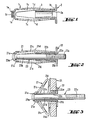
- the expansion dowel shown in FIG. 1 has a dowel body, generally designated 1, with a front end 1 a in the setting direction and a rear end 1. Between the front end 1a and the rear end 1b of the dowel body 1, radially bendable spreading arms 1c extend with a fold point 1d arranged approximately in the central area. At the front end 1a of the dowel body 1, the spreading arms 1c are connected to one another via a connection point 1e. The connection point 1e is provided with an internal thread 1f as a means of engagement for load absorption.
- the rear end 1 of the dowel body 1 is connected to a flange denoted overall by 2.
- the flange 2 has a projection 2a partially projecting into the rear end 1b of the dowel body 1.
- a sleeve-shaped stop part 3 is also arranged in the dowel body 1.
- the stop part 3 limits the axial compression of the dowel body 1 or the radial buckling of the spreading arms 1c.
- the stop part 3 is connected to the flange 2 or to the dowel body 1, for example by welding, soldering or gluing.
- the inner diameter of the stop part 3 corresponds approximately to that of the flange 2.
- a tension dome not shown, which is provided with a thread corresponding to the internal thread 1f, is screwed through the flange 2 and the stop part 3 into the internal thread 1f of the dowel body 1.
- the dowel body 1 is then axially compressed and anchored by a tensile load applied to this dome.
- the expansion plug shown in FIGS. 2 and 3 consists of a plug body designated overall by 21 and an associated flange designated overall as 22.
- the dowel body 21 has a front end 21a in the setting direction and a rear end 21b. Radially foldable spreading arms 21c extend in between.
- the spreading arms 2le have a folding point 21 and are connected to one another at their front end via a connecting point 21e.
- the flange 22 has a sleeve-shaped stop part 22b which is integrally connected to the flange 22.
- the dowel body 21 and the flange 22 are penetrated by a tension bolt, designated overall by 23.
- the tension bolt 23 has a head 23a resting on the front end 21a of the dowel body 21 and a shaft 23b. The rear end portion of the shaft 23b is provided with a thread 23c.
- the dowel is inserted into a thin-walled component, generally designated 24, and axially compressed.
- the component 24 has a receiving bore 24a for the dowel body 21.
- the radial buckling of the expansion arms 21c or the upsetting of the dowel body 21 is limited by the sleeve-shaped stop part 22b.
- the connection point 21 e comes to rest on the free end of the stop part 22b.
Landscapes
- Engineering & Computer Science (AREA)
- General Engineering & Computer Science (AREA)
- Mechanical Engineering (AREA)
- Dowels (AREA)
- Joining Of Building Structures In Genera (AREA)
- Panels For Use In Building Construction (AREA)
Description
- Die Erfindung betrifft einen Spreizdübel zur Befestigung an dünnwandigen Bauteilen, mit einem Dübelkörper mit unter axialer Stauchung radial ausknickbaren Spreizarmen, die am in Einführrichtung rückwärtigen Ende einen als Widedager dienenden Flansch aufweisen und an ihrem in Einführrichtung vorderen Ende miteinander verbunden sowie an der Verbindungsstelle mit Angriffsmitteln zur Lastaufnahme versehen sind, wobei zwischen den Spreizarmen sowie zwischen dem Flansch und der die Angriffsmittel aufweisenden Verbindungsstelle der Spreizarme ein sich im ungespreizten Zustand des Dübels etwa entlang der Hälfte des Abstandes zwischen dem Flansch und der die Angriffsmittel aufweisenden Verbindungsstelle der Spreizarme erstreckendes, die axiale Stauchung begrenzendes Anschlagteil vorgesehen ist.
- Zur Befestigung an nur von einer Seite zugänglichen, dünnwandigen Bauteilen, wie Platten oder Hohlräume aufweisenden Aufnahmematerialien werden aus der DE-A-2 819 862 bekannte, sogenannte Hohlraumdübel verwendet. Zur Verankerung werden diese Dübel bis zur Anlage des Flansches an der Oberfläche des Aufnahmematerials in eine Aufnahmebohrung eingeführt. Dabei ist der Dübel so dimensioniert, dass er sich über den Grossteil seiner Länge über das Aufnahmematerial hinaus in den dahinterliegenden Hohlraum erstreckt. Anschliessend wird der Dübel beispielsweise mittels eines einen Zugdom aufweisenden Spezialwerkzeuges oder eines Gewindebolzens axial gestaucht, so dass die Spreizarme radial ausknicken und das Aufnahmematerial hintergreifen. Das Ausmass dieser Stauchung ist von aussen nicht ersichtlich, so dass lediglich über das Ansteigen des Verformungswiderstandes gewisse Rückschlüsse über den Verankerungszustand des Dübels gezogen werden können. Zur Begrenzung der axialen Stauchung weist dieser Dübel ein sich etwa entlang der Hälfte des Abstandes zwischen dem Flansch und der die Angriffsmittel aufweisenden Verbindungsstelle der Spreizarme erstreckendes Anschlagteil auf. Dabei ist der Dübel samt dem Anschlagteil einstückig aus Kunststoff gespritzt.
- Neben den aus Kunststoff bestehenden Dübeln werden für gewisse Anwendungen bevorzugt entsprechende Ausführungen aus Metall verwendet. Diese Dübel bestehen meist aus Blech und weisen dadurch gegenüber den aus Kunststoff bestehenden Dübeln höhere Festigkeitswerte auf und sind zudem hitzebeständig.
- Bei der Verwendung dieser aus Metall bestehenden Spreizdübel in weichen Aufnahmematerialien, wie Kunststoff oder dgl. hat sich gezeigt, dass ein Ueberspreizen des Dübels möglich ist, wobei es zu Beschädigungen des Aufnahmematerials und des Dübels kommen kann. Solche Schäden sind von aussen meist nicht erkennbar und können daher bei Belastung zu Ausfällen des Dübels führen.
- Der Erfindung liegt die Aufgabe zugrunde, einen wirtschaftlich herstellbaren und hohe Fertigkeitswerte aufweisenden Spreizdübel zu schaffen, bei dem ein Ueberspreizen, beispielsweise bei Anwendung in weichen Aufnahmematerialien, nicht auftritt.
- Gemäss der Erfindung wird dies dadurch erreicht, dass der Dübelkörper und der Flansch zweiteilig ausgebildet sind, wobei das Anschlagteil als hülsenförmige Verlängerung eines in den Dübelkörper hineinragenden Ansatzes des Flansches ausgebildet ist.
- Ein solches Anschlagteil wird mit dem Flansch als separates Teil hergestellt und anschliessend mit dem Dübel verbunden. Dadurch kann derselbe Dübel durch Zuordnung entsprechender Anschlagteile für Aufnahmematerialien von unterschiedlicher Dicke verwendet werden. Die einstückige Ausbildung des Anschlagteils mit dem Flansch ist besonders wirtschaftlich, da die Möglichkeit besteht, den Spreizdübel aus zwei kaltverformbaren Teilen herzustellen und in einem nachfolgenden Arbeitsgang miteinander zu verbinden. Das aussenseitige Anschlagen der Spreizarme an der als Anschlagteil wirkenden hülsenförmigen Verlängerung führt zum Vorteil, dass bei unterschiedlichen Längentoleranzen der Spreizarme die gesamte Dübellänge trotzdem eingehalten werden kann.
- Für eine einfache Herstellung ist es zweckmässig, dass der Innendurchmesser des als hülsenförmige Verlängerung ausgebildeten Anschlagteils etwa demjenigen des Flansches entspricht.
- Das Spreizen durch axiales Stauchen des Dübels kann beispielsweise mittels eines separaten Setzwerkzeuges oder mittels eines mit dem Dübel zu verbindenden bzw. verbundenen Befestigungselementes erfolgen. Das Setzwerkzeug kann einen mit den Angriffsmitteln des Dübels zur Lastaufnahme zu verbindenden Zugdom aufweisen oder an einem dem Dübel zugeordneten und mit diesem verbundenen Zugbolzen angesetzt werden. Das Befestigungselement kann ein in ein Innengewinde des Dübels einzuschraubender Gewindebolzen oder eine auf einen mit dem Dübel verbundenen Gewindebolzen aufzuschraubende Mutter sein. Durch einen demjenigen des Flansches entsprechenden Innendurchmesser des Anschlagteiles wird der Durchmesser des Zugdoms oder Gewindebolzens durch das Anschlagteil nicht beschränkt. Somit können für Dübel einer bestimmten Grösse mit Anschlagteil dieselben Setzwerkzeuge verwendet werden wie für einen entsprechenden Dübel ohne Anschlagteil. Dies bedeutet insbesondere für den Anwender eine wesentliche Vereinfachung.
- Die Erfindung soll nachstehend anhand der sie beispielsweise wiedergebenden Zeichnungen näher erläutert werden. Es zeigen :
- Fig. 1 eine erste Ausführung des erfindungsgemässen Dübels, in ungespreiztem Zustand,
- Fig. 2 eine weitere Ausführung eines erfindungsgemässen Spreizdübels, in ungespreiztem Zustand,
- Fig. 3 den Dübel gemäss Fig. 2, in verankertem Zustand.
- Der aus Fig. 1 ersichtliche Spreizdübel weist einen insgesamt mit 1 bezeichneten Dübelkörper mit einem in Setzrichtung vorderen Ende 1 a und einem rückwärtigen Ende 1 auf. Zwischen dem vorderen Ende 1a und dem rückwärtigen Ende 1b des Dübelkörpers 1 erstrecken sich radial ausknickbare Spreizarme 1c mit einer etwa im mittleren Bereich angeordneten Faltstelle 1d. Am vorderen Ende 1a des Dübelkörpers 1 sind die Spreizarme 1c über eine Verbindungsstelle 1e miteinander verbunden. Die Verbindungsstelle 1e ist mit einem Innengewinde 1f als Angriffsmittel zur Lastaufnahme versehen. Das rückwärtige Ende 1 des Dübelkörpers 1 ist mit einem insgesamt mit 2 bezeichneten Flansch verbunden. Der Flansch 2 weist einen teilweise in das rückwärtige Ende 1 b des Dübelkörpers 1 ragenden Ansatz 2a auf. Im Dübelkörper 1 ist femer ein hülsenförmiges Anschlagteil 3 angeordnet. Das Anschlagteil 3 begrenzt die axiale Stauchung des Dübelkörpers 1 bzw das radiale Ausknicken der Spreizarme 1c. Das Anschlagteil 3 ist beispielsweise durch Schweissen, Löten oder Kleben mit dem Flansch 2 bzw mit dem Dübelkörper 1 verbunden. Der Innendurchmesser des Anschlagteils 3 entspricht etwa demjenigen des Flansches 2. Zum Spreizen des Dübels wird ein nicht dargestellter, mit einem dem Innengewinde 1f entsprechenden Gewinde versehener Zugdom durch den Flansch 2 und das Anschlagteil 3 hindurch in das Innengewinde 1f des Dübelkörpers 1 eingeschraubt. Durch eine an diesem Zugdom aufgebrachte Zugbelastung wird anschliessend der Dübelkörper 1 axial gestaucht und verankert.
- Der aus den Fig. 2 und 3 ersichtliche Spreizdübei besteht aus einem insgesamt mit 21 bezeichneten Dübelkörper und einem damit verbundenen insgesamt mit 22 bezeichneten Flansch. Der Dübelkörper 21 weist ein in Setzrichtung vorderes Ende 21a sowie ein rückwärtiges Ende 21b auf. Dazwischen erstrecken sich radial ausknickbare Spreizarme 21c. Die Spreizarme 2le weisen eine Faltstelle 21 auf und sind an ihrem vorderen Ende über eine Verbindungsstelle 21e untereinander verbunden. Der Flansch 22 weist ein hülsenförmig ausgebildetes, mit dem Flansch 22 einstückig verbundenes Anschlagteil 22b auf. Der Dübelkörper 21 und der Flansch 22 werden von einem insgesamt mit 23 bezeichneten Zugbolzen durchsetzt. Der Zugbolzen 23 weist einen am vorderen Ende 21a des Dübelkörpers 21 anliegenden Kopf 23a sowie einen Schaft 23b auf. Der rückwärtige Endbereich des Schaftes 23b ist mit einem Gewinde 23c versehen.
- In Fig. 3 ist der Dübel in ein dünnwandiges, insgesamt mit 24 bezeichnetes Bauteil eingesetzt und axial gestaucht. Das Bauteil 24 weist eine Aufnahmebohrung 24a für den Dübelkörper 21 auf. Das radiale Ausknicken der Spreizarme 21c bzw. das Stauchen des Dübelkörpers 21 wird durch das hülsenförmige Anschlagteil 22b begrenzt. Die Verbindungsstelle 21 e kommt dabei am freien Ende des Anschlagteiles 22b zur Anlage.
Claims (2)
Priority Applications (1)
| Application Number | Priority Date | Filing Date | Title |
|---|---|---|---|
| AT85810534T ATE43887T1 (de) | 1984-12-20 | 1985-11-13 | Spreizduebel fuer duennwandige bauteile. |
Applications Claiming Priority (2)
| Application Number | Priority Date | Filing Date | Title |
|---|---|---|---|
| DE19843446516 DE3446516A1 (de) | 1984-12-20 | 1984-12-20 | Spreizduebel fuer duennwandige bauteile |
| DE3446516 | 1984-12-20 |
Publications (2)
| Publication Number | Publication Date |
|---|---|
| EP0189000A1 EP0189000A1 (de) | 1986-07-30 |
| EP0189000B1 true EP0189000B1 (de) | 1989-06-07 |
Family
ID=6253326
Family Applications (1)
| Application Number | Title | Priority Date | Filing Date |
|---|---|---|---|
| EP85810534A Expired EP0189000B1 (de) | 1984-12-20 | 1985-11-13 | Spreizdübel für dünnwandige Bauteile |
Country Status (5)
| Country | Link |
|---|---|
| US (1) | US4752168A (de) |
| EP (1) | EP0189000B1 (de) |
| JP (1) | JPH0697042B2 (de) |
| AT (1) | ATE43887T1 (de) |
| DE (2) | DE3446516A1 (de) |
Families Citing this family (25)
| Publication number | Priority date | Publication date | Assignee | Title |
|---|---|---|---|---|
| US4828439A (en) * | 1987-05-15 | 1989-05-09 | Giannuzzi Louis | Screw anchor |
| JPH0429123Y2 (de) * | 1987-12-02 | 1992-07-15 | ||
| DE3904404A1 (de) * | 1989-02-14 | 1990-08-16 | Hennig Hans Juergen Dipl Des M | Vorrichtung zur herstellung eines anker- oder aufhaengepunkts an hohlkoerpern oder hohlraeumen |
| FR2647166B1 (fr) * | 1989-05-19 | 1991-07-12 | Garonne Ets Auriol & Cie | Organe de rivetage aveugle, procede d'assemblage et assemblages obtenus |
| US5078561A (en) * | 1990-11-08 | 1992-01-07 | Illinois Tools Works, Inc. | Plastic expansion nut |
| US5326205A (en) * | 1992-05-27 | 1994-07-05 | Anspach Jr William E | Expandable rivet assembly |
| DE19512415A1 (de) * | 1995-04-03 | 1996-10-10 | Hilti Ag | Spreizdübel |
| DE19629576A1 (de) * | 1996-07-11 | 1998-01-22 | Dorothee Sagebiel | Spannbolzen für Bauteile |
| IT1284905B1 (it) * | 1996-10-02 | 1998-05-28 | Massimo Spinelli | Elemento di ancoraggio |
| US5775859A (en) * | 1997-06-06 | 1998-07-07 | National Molding Corp. | Mat fastener |
| DE19833070A1 (de) * | 1998-07-23 | 2000-01-27 | Fischer Artur Werke Gmbh | Spreizanker aus Metall |
| DE10010800A1 (de) * | 2000-03-08 | 2001-09-27 | Karl Woltering Gmbh | Befestigungsvorrichtung für die Montage in Hohlmauerwerk und Hohlwänden bzw. Hohldecken sowie Verfahren zur Anbringung einer Befestigungsvorrichtung |
| JP2003028120A (ja) * | 2001-07-17 | 2003-01-29 | Wakai & Co Ltd | 拡開アンカー |
| US6935821B2 (en) * | 2002-04-05 | 2005-08-30 | Illinois Tool Works, Inc. | Mushrooming expandable anchor |
| US6991601B2 (en) * | 2002-12-02 | 2006-01-31 | Ams Research Corporation | Implantable pump |
| US7252469B2 (en) * | 2003-06-09 | 2007-08-07 | Ford Global Technologies, Llc | Rivet nut with machinable head and method of making a vehicle body |
| US7632277B2 (en) * | 2004-03-29 | 2009-12-15 | Woll Bioorthopedics Llc | Orthopedic intramedullary fixation system |
| US7887273B2 (en) * | 2005-09-15 | 2011-02-15 | Newfrey Llc | Blind rivet and method |
| DE102008009917B4 (de) * | 2008-02-15 | 2013-10-10 | Margit Liebl | Verbindungsvorrichtung mit Spreizverschluss |
| ITTO20080359A1 (it) * | 2008-05-14 | 2009-11-15 | Itw Construction Products Ital | Tassello ad espansione |
| US8258395B2 (en) * | 2009-02-24 | 2012-09-04 | Sunpower Corporation | Photovoltaic module and interlocked stack of photovoltaic modules |
| JP2018013151A (ja) * | 2016-07-20 | 2018-01-25 | ポップリベット・ファスナー株式会社 | ブラインドナット、ブラインドナット組立体、及び締結構造 |
| US10907672B1 (en) * | 2017-07-28 | 2021-02-02 | Robert Kollker John | Door knob screw alignment sleeve |
| US20210222724A1 (en) * | 2020-01-16 | 2021-07-22 | Illinois Tool Works Inc. | Fastening nut and fastening assembly |
| JP7744695B2 (ja) * | 2023-09-06 | 2025-09-26 | 株式会社ロブテックス | 一方向締結具 |
Family Cites Families (17)
| Publication number | Priority date | Publication date | Assignee | Title |
|---|---|---|---|---|
| US1881973A (en) * | 1930-12-31 | 1932-10-11 | Schmitt Alfred | Screw plug for plastic walls |
| US2236079A (en) * | 1940-02-23 | 1941-03-25 | Mone B Call | Wall bolt |
| US2397111A (en) * | 1942-08-10 | 1946-03-26 | Huxon Holding Corp | Rivet |
| CA432954A (en) * | 1943-01-29 | 1946-02-05 | Harold Gill Ray | Tubular rivet |
| US2964989A (en) * | 1948-07-01 | 1960-12-20 | Croessant Machine Works Inc | Expanding screw anchor |
| US2559281A (en) * | 1948-07-01 | 1951-07-03 | Croessant George Frederick | Anchoring socket for bolts |
| US3143916A (en) * | 1962-04-03 | 1964-08-11 | A A Rice Inc | Collapsible self-anchoring device |
| US3253495A (en) * | 1962-12-06 | 1966-05-31 | Huck Mfg Co | Hardened blind bolt with annealed shank portion |
| BE795670A (fr) * | 1972-02-22 | 1973-06-18 | Dunlop Ltd | Perfectionnements aux roues chaussees |
| US3888156A (en) * | 1974-03-29 | 1975-06-10 | Raoul Fima | Anchor bolt construction |
| US4364697A (en) * | 1977-12-12 | 1982-12-21 | Sps Technologies, Inc. | Blind fastener assembly |
| DE2809644A1 (de) * | 1978-03-06 | 1979-09-20 | Hilti Ag | Duebel zum befestigen an hohlraeumen |
| DE2819862A1 (de) * | 1978-05-05 | 1979-11-08 | Hilti Ag | Spreizduebel zur hintergreifenden befestigung |
| US4312613A (en) * | 1979-05-11 | 1982-01-26 | Binns Lloyd Sylvester | Blind rivet assembly |
| JPS5715110A (en) * | 1980-06-30 | 1982-01-26 | Matsushita Electric Works Ltd | Expansion bolt |
| DE8032695U1 (de) * | 1980-12-09 | 1982-09-30 | Hilti AG, 9494 Schaan | Spreizduebel fuer platten, mauerwerk und dgl. hohlraeume aufweisende bauteile |
| US4457652A (en) * | 1981-04-13 | 1984-07-03 | Pratt John D | Composite buckling blind fastener |
-
1984
- 1984-12-20 DE DE19843446516 patent/DE3446516A1/de not_active Withdrawn
-
1985
- 1985-11-13 EP EP85810534A patent/EP0189000B1/de not_active Expired
- 1985-11-13 DE DE8585810534T patent/DE3570907D1/de not_active Expired
- 1985-11-13 AT AT85810534T patent/ATE43887T1/de not_active IP Right Cessation
- 1985-12-18 US US06/810,641 patent/US4752168A/en not_active Expired - Fee Related
- 1985-12-19 JP JP60284464A patent/JPH0697042B2/ja not_active Expired - Lifetime
Also Published As
| Publication number | Publication date |
|---|---|
| DE3570907D1 (en) | 1989-07-13 |
| ATE43887T1 (de) | 1989-06-15 |
| EP0189000A1 (de) | 1986-07-30 |
| JPH0697042B2 (ja) | 1994-11-30 |
| DE3446516A1 (de) | 1986-06-26 |
| JPS61153009A (ja) | 1986-07-11 |
| US4752168A (en) | 1988-06-21 |
Similar Documents
| Publication | Publication Date | Title |
|---|---|---|
| EP0189000B1 (de) | Spreizdübel für dünnwandige Bauteile | |
| DE19539685B4 (de) | Verbindungseinheit, Verbindungsverfahren und Niet zu ihrer Herstellung | |
| EP0356425B1 (de) | Ankerstange für einen kunstharzklebeanker | |
| EP1040544B1 (de) | Steckdübel | |
| EP2158406A2 (de) | Befestigungsbeschlag für eine leichtbauplatte | |
| CH656193A5 (de) | Spreizduebel. | |
| DE68902323T2 (de) | Blindniet. | |
| DE19603265A1 (de) | Spreizdübel | |
| EP0555542A1 (de) | Anker zur Verankerung mittels einer Verbundmasse in einem Bohrloch eines Betonteiles | |
| EP0028671A1 (de) | Rohranschluss zum Verbinden von Rohren mit Flanschen, Voll- oder Hohlprofilen und Verfahren zur Herstellung des Rohranschlusses | |
| DE2744036A1 (de) | Befestigungsvorrichtung, insbesondere zur befestigung von dachplatten o.dgl. mit isolierender zwischenlage auf gebaeudeteilen | |
| EP1277972B1 (de) | Spreizdübel | |
| EP0187168A1 (de) | Befestigungselement | |
| EP0728882B1 (de) | Befestigungselement zum Befestigen von Platten grosser Dicke an Bauteilen | |
| EP0908634B1 (de) | Einschlagdübel | |
| DE102009053848A1 (de) | Nagel zum Eintreiben in mindestens ein nicht vorgelochtes Bauteil | |
| EP2083179B1 (de) | Verbindungselement | |
| EP0070976B1 (de) | Schlagspreizdübel | |
| DE3820351A1 (de) | Befestigungsmittel fuer eine stumpfe befestigung zweier holzelemente miteinander | |
| EP0738835B1 (de) | Dübel mit einer Siebhülse | |
| EP1970575A2 (de) | Spreizdübel für zweischaliges Mauerwerk | |
| DE19632469A1 (de) | Nagel mit aufspreizbaren Beinen | |
| EP0166134A1 (de) | Blindnietartiges Verbindungselement | |
| DE8106956U1 (de) | Spreizdübel | |
| EP0058709A1 (de) | Ankerbolzen |
Legal Events
| Date | Code | Title | Description |
|---|---|---|---|
| PUAI | Public reference made under article 153(3) epc to a published international application that has entered the european phase |
Free format text: ORIGINAL CODE: 0009012 |
|
| AK | Designated contracting states |
Kind code of ref document: A1 Designated state(s): AT CH DE FR GB LI NL SE |
|
| 17P | Request for examination filed |
Effective date: 19860825 |
|
| 17Q | First examination report despatched |
Effective date: 19870504 |
|
| GRAA | (expected) grant |
Free format text: ORIGINAL CODE: 0009210 |
|
| AK | Designated contracting states |
Kind code of ref document: B1 Designated state(s): AT CH DE FR GB LI NL SE |
|
| REF | Corresponds to: |
Ref document number: 43887 Country of ref document: AT Date of ref document: 19890615 Kind code of ref document: T |
|
| REF | Corresponds to: |
Ref document number: 3570907 Country of ref document: DE Date of ref document: 19890713 |
|
| ET | Fr: translation filed | ||
| GBT | Gb: translation of ep patent filed (gb section 77(6)(a)/1977) | ||
| PLBE | No opposition filed within time limit |
Free format text: ORIGINAL CODE: 0009261 |
|
| STAA | Information on the status of an ep patent application or granted ep patent |
Free format text: STATUS: NO OPPOSITION FILED WITHIN TIME LIMIT |
|
| 26N | No opposition filed | ||
| EAL | Se: european patent in force in sweden |
Ref document number: 85810534.9 |
|
| PGFP | Annual fee paid to national office [announced via postgrant information from national office to epo] |
Ref country code: SE Payment date: 19951018 Year of fee payment: 11 Ref country code: FR Payment date: 19951018 Year of fee payment: 11 |
|
| PGFP | Annual fee paid to national office [announced via postgrant information from national office to epo] |
Ref country code: DE Payment date: 19951030 Year of fee payment: 11 |
|
| PGFP | Annual fee paid to national office [announced via postgrant information from national office to epo] |
Ref country code: NL Payment date: 19951130 Year of fee payment: 11 Ref country code: CH Payment date: 19951130 Year of fee payment: 11 |
|
| PGFP | Annual fee paid to national office [announced via postgrant information from national office to epo] |
Ref country code: GB Payment date: 19961101 Year of fee payment: 12 |
|
| PG25 | Lapsed in a contracting state [announced via postgrant information from national office to epo] |
Ref country code: SE Effective date: 19961114 |
|
| PG25 | Lapsed in a contracting state [announced via postgrant information from national office to epo] |
Ref country code: LI Effective date: 19961130 Ref country code: CH Effective date: 19961130 |
|
| PG25 | Lapsed in a contracting state [announced via postgrant information from national office to epo] |
Ref country code: NL Effective date: 19970601 |
|
| REG | Reference to a national code |
Ref country code: CH Ref legal event code: PL |
|
| PG25 | Lapsed in a contracting state [announced via postgrant information from national office to epo] |
Ref country code: FR Effective date: 19970731 |
|
| NLV4 | Nl: lapsed or anulled due to non-payment of the annual fee |
Effective date: 19970601 |
|
| PG25 | Lapsed in a contracting state [announced via postgrant information from national office to epo] |
Ref country code: DE Effective date: 19970801 |
|
| EUG | Se: european patent has lapsed |
Ref document number: 85810534.9 |
|
| PGFP | Annual fee paid to national office [announced via postgrant information from national office to epo] |
Ref country code: AT Payment date: 19970904 Year of fee payment: 13 |
|
| REG | Reference to a national code |
Ref country code: FR Ref legal event code: ST |
|
| PG25 | Lapsed in a contracting state [announced via postgrant information from national office to epo] |
Ref country code: GB Free format text: LAPSE BECAUSE OF NON-PAYMENT OF DUE FEES Effective date: 19971113 |
|
| GBPC | Gb: european patent ceased through non-payment of renewal fee |
Effective date: 19971113 |
|
| PG25 | Lapsed in a contracting state [announced via postgrant information from national office to epo] |
Ref country code: AT Free format text: LAPSE BECAUSE OF NON-PAYMENT OF DUE FEES Effective date: 19981113 |