EP0187970A1 - Aufhängung für gelenktes Rad eines Fahrzeuges - Google Patents
Aufhängung für gelenktes Rad eines Fahrzeuges Download PDFInfo
- Publication number
- EP0187970A1 EP0187970A1 EP85115930A EP85115930A EP0187970A1 EP 0187970 A1 EP0187970 A1 EP 0187970A1 EP 85115930 A EP85115930 A EP 85115930A EP 85115930 A EP85115930 A EP 85115930A EP 0187970 A1 EP0187970 A1 EP 0187970A1
- Authority
- EP
- European Patent Office
- Prior art keywords
- rod
- cup
- fact
- integral
- pin
- Prior art date
- Legal status (The legal status is an assumption and is not a legal conclusion. Google has not performed a legal analysis and makes no representation as to the accuracy of the status listed.)
- Withdrawn
Links
Images


Classifications
-
- B—PERFORMING OPERATIONS; TRANSPORTING
- B60—VEHICLES IN GENERAL
- B60G—VEHICLE SUSPENSION ARRANGEMENTS
- B60G15/00—Resilient suspensions characterised by arrangement, location or type of combined spring and vibration damper, e.g. telescopic type
- B60G15/02—Resilient suspensions characterised by arrangement, location or type of combined spring and vibration damper, e.g. telescopic type having mechanical spring
- B60G15/06—Resilient suspensions characterised by arrangement, location or type of combined spring and vibration damper, e.g. telescopic type having mechanical spring and fluid damper
- B60G15/067—Resilient suspensions characterised by arrangement, location or type of combined spring and vibration damper, e.g. telescopic type having mechanical spring and fluid damper characterised by the mounting on the vehicle body or chassis of the spring and damper unit
- B60G15/068—Resilient suspensions characterised by arrangement, location or type of combined spring and vibration damper, e.g. telescopic type having mechanical spring and fluid damper characterised by the mounting on the vehicle body or chassis of the spring and damper unit specially adapted for MacPherson strut-type suspension
Definitions
- the present invention relates to a perfected vehicle steering wheel suspension, designed to provide for greater driving comfort and smoother steering performance.
- Vehicle steering wheels usually the front wheels
- McPherson type suspensions designed to allow limited displacement, when steering, of the shock absorber and the coil spring supported on the same; both of the latter being known to be secured, at one end, to the wheel hub and, at the opposite end, to the vehicle body, in particular, in "domes" formed on specific parts of the vehicle body.
- the aim of the present invention is to provide a suspension with a perfected flexible connecting assembly designed to totally eliminate resistance on the said assembly, even in the presence of complex mutual displacement of the shock absorber and body caused by simultaneous rotation and jolting of the wheels on which the said suspension is fitted.
- the present invention relates to a vehicle steering wheel suspension comprising a shock absorber connectable, at one end, to a respective wheel hub and, at the opposite end, to a body portion of the said vehicle, a coil spring on the said shock absorber, and a flexible assembly designed to secure a rod on the said shock absorber to the said body portion; characterised by the fact that the said flexible assembly comprises a flexible rubber pad securable to the said body portion, a plate for supporting one end of said spring, and a ball joint connecting the said rod integral with the said flexible pad, in such a manner as to enable the said shocker absorber to move in any direction in relation to the said flexible pad, subsequent to jolting and/or steering of the said wheel.
- Number 1 in Fig.1 indicates a front steering suspension for a wheel 2 on any known type of vehicle (not shown for simplicity), the said suspension being designed to enable support of the said wheel 2 by a portion 3 of the said vehicle body, the said portion 3 consisting, for example, of a "dome” formed in an appropriate position on the said vehicle (not shown).
- suspension 1 is a McPherson type, though clearly the following description may apply indifferently to any other known type of suspension designed to support the steering wheels of a vehicle.
- suspension 1 comprises a known type of shock absorber 4 connectable, at the lower end, to a respective wheel hub 5 and, at the opposite end, to the said body portion 3, a coil spring 6 fitted in known manner onto shock absorber 4, and a flexible assembly 7 designed to secure the top of rod 8 on shock absorber 4 to the said body portion 3.
- shock absorber 4 also comprises a body 9 to which is secured the lower end 10 of spring 6, and which is fitted integral with wheel hub 5, supporting wheel 2, by means of a known type of coupling 11.
- Suspension 1 also comprises two connecting arms, 12 and 13, the former for connecting a wheel 2 steering mechanism and the latter for connecting a rocker arm 14 connected in known manner to the body of the said vehicle (not shown), and a homokinetic coupling 15 for transmitting the drive torque to wheel hub 5.
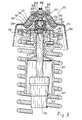
- assembly 7 is fitted integral with rod 8 on shock absorber 4 and comprises a plate 16 for supporting the top end 18 of spring 6, a flexible rubber pad 19 securable in known manner to the said dome-shaped body portion 3, preferably by means of screws or bolts 20, and a ball joint 21 connecting rod 8 integral with flexible pad 19.
- assembly 7 is fitted integral with the top end 22 of rod 8
- plate 16 is fitted angularly integral with end 22, for example, by means of sleeve 23.
- joint 21 comprises a pin 25, a cup-shaped body 26 secured integral with flexible pad 19, and at least one pair of opposed semispherical thrust bearings 27 arranged facing each other, gripping pin 25 and housed inside the said cup-shaped body 26.
- pin 25 is fitted integral with rod 8, projecting in relation to end 22, and is provided on its free end with a spherical bulb 29 housed in mobile manner inside a spherical cavity 30 defined by the said thrust bearings 27.
- the latter are gripped onto pin 25 and locked inside cup-shaped body 26, in such a manner as to universally secure bulb 29 onto body 26, by means, for example, of a threaded ring nut 31, screwed into the mouth of body 26, and by means of respective Belleville washers 32 secured onto thrust bearings 27 by ring nut 31 and also designed to take up any working slack caused by wear on bulb 29 or thrust bearings 27.
- pin 25 is secured onto end 22 by means of a threaded coupling 35, so as to enable assembly of sleeve 23 and allow plate 16 to be locked onto rod 8.
- Pin 25, may obviously be formed integral in one piece with rod 8, in which case, place 16 and joint 21 must be assembled prior to inserting rod 8 inside body 9.
- Flexible pad 19 is of essentially known structure and comprises an essentially rigid, cup-shaped outer sleeve 38 made of metal, a rigid sleeve 39, also cup-shaped, concentric with sleeve 38 and constituting the innermost part of paid 19, and an intermediate, elastically deformable sleeve 40 made of rubber or any other elastomer and preferably vulcanized to both sleeves 39 and 38 in such a manner as to secure the latter together elastically.
- Inner sleeve 39 is designed to house body 26 and is secured integral with the same in any convenient manner, e.g. force fitted or welded.
- a stop cap 50 may conveniently be fitted integral with the bottom wall on body 26, subsequent to insertion of the latter inside sleeve 39, in such a manner as to prevent accidental withdrawal of the said body 26 and, with it joint 21, from sleeve 39.
- Body 26 is preferably clicked into sleeve 39 by means of appropriate sizing of the latter, so that, during assembly, pad 19 may be fitted straight onto vehicle body portion 3, using screws 20, whereas joint 21 and plate 16 may be fitted separately onto shock absorber 4, in such a manner as to form a subassembly, which may subsequently be clicked onto the vehicle body in one single operation, by inserting body 26 inside sleeve 39.
- subsequent assembly of stop cap 50 presents any possibility of accidental withdrawal of joint 21 from pad 19, once suspension 1 is fully assembled.
- shock absorber 4 is free to move in any direction in relation to pad 1 9 and the vehicle body, thus enabling shock absorber 4 to accompany any jolting or steering control movement of wheel 2.
- rod 8 and plate 1 6 are free, not only to turn in relation to body portion 3, but also to change position in relation to the same by rocking conically about the axis of symmetry of sleeves 38 and 39. This prevents any resistance developing on flexible assembly 7 according to the present invention, even in the event of severe jolting or steering of the wheel supported on the suspension, thus providing for greater driving comfort and easier steering of the vehicle fitted with such a suspension.
- a suspension of the type described herein is relatively cheap to produce and extremely easy to assemble. Furthermore, part of the suspension may be assembled off-line, as a subassembly, thus providing for more accurate assembly and even lower cost.
- the foregoing characteristics, in particular, easy assembly and low-cost production, may be considerably improved by adopting, in place of suspension 1 as described, the variation shown in detail in Fig.3.
- Suspension 1 0 1 is also preferably a McPherson type, though the following description may obviously apply to any other known type of suspension designed for the purpose of supporting steering wheels.
- Suspension 10 1 comprises a known type of shock absorber 10 4 connectable, at the bottom end, to the said wheel and, at the top end, to "dome” 103, a coil spring 106 fitted in known manner onto shock absorber 104, and a flexible assembly 107 designed to secure the top of rod 108 in shock absorber 104 to "dome” 103.
- shock absorber 104 also comprises a body 109 to which is secured in known manner (not shown) the bottom end of spring 106 and which is fitted integral in known manner to the said vehicle wheel, and a sleeve 200 fitted onto the top of body 109 for protecting rod 108.
- Flexible assembly 107 is integral with rod 108 on shock absorber 104 and comprises a plate 116 for supporting the top end 118 of spring 106, a rubber paid 119 securable to "dome" 103 in any appropriate manner (not shown), e.g. by means of screws or bolts, or formed integral with the same, and a ball joint 121 universally connecting rod 1 08 integral with flexible pad 1 19.
- flexible assembly 107 is fitted in integral manner onto the top end 122 (preferably threaded) of rod 108, whereas plate 116 is fitted angularly integral with end 122, either directly or, as shown, indirectly by means of joint 121.
- the said joint 121 comprises a pin 125, a cup-shaped casing 126 secured integral with rod 108 and fitted externally integral with plate 1 1 6, and at least one pair of opposed semispherical thrust bearings 127 arranged facing each other, gripping pin 125 and, in turn, housed inside cup-shaped casing 126.
- Flexible pad 119 is of essentially known structure and comprises an essentially rigid, cup-shaped outer sleeve 138 made of metal and, for example, formed integral with dome 103, a rigid sleeve 139 also cup-shaped, concentric with sleeve 138 and constituting the innermost part of pad 119, and an intermediate, elastically deformable sleeve 140 made of rubber or any other elastomer and preferably vulcanized to both sleeves 139 and 138 in such a manner as to secure the latter together elastically.
- Inner sleeve 139 is designed in such a manner as to house joint 121 and is preferably provided at the top with an outer stop cap 150 secured in any appropriate manner, e.g. welded, and designed to cooperate with a top appendix 201 in elastomer sleeve 140 in such a manner as to limit the vertical stroke of shock absorber 104 allowed by flexible pad 119.
- pin 125 is secured integral and in projecting manner inside sleeve 139 by means of a threaded coupling consisting of a threaded end 202 on pin 125 and a respective nut 203 provided with appropriate locking means.
- Pin 125 is also provided on its free end with a spherical bulb 129 housed in idle manner' inside a spherical cavity 1 30 defined by thrust bearings 127.
- the latter are gripped onto pin 125 and locked inside cup-shaped body 126, in such a manner as to universally secure bulb 129 to body 126, by retaining means preferably consisting of a bottom wall 205 on casing 126, the said wall having a centre through hole 206 enabling entry of the free end of pin 125 inside casing 126, and a funnel-shaped end 210 on casing 126 located opposite the said bottom wall 205 and calked or pressed in any permanently deformable manner onto lower thrust bearing 127.
- end 210 is provided with a threaded sleeve 211 designed to screw onto threaded end 122 of rod 108 for securing casing 126 to the same, and is fitted integral on the outside with plate 116 which is fitted onto funnel-shaped end 210 in any appropriate manner, e.g. by permanent deformation or welding.
- sleeve 211 is secured angularly integral with rod 108 by means of a tab 212 bent inside a side cavity 213 formed on rod 108 next to end 122.
- suspension 101 may be assembled by first assembling joint 121, by fitting bulb 129 and thrust bearings 127 inside casing 126 and permanently deforming funnel-shaped end 210, and then assembling the joint 121 so formed onto shock absorber 104 by screwing and then locking sleeve 211 onto threaded end 122, after first fitting plate 116 onto casing 126.
- the subassembly so formed may then be fitted directly onto flexible pad 119 by locking pin 125, by means of nut 203, onto inner sleeve 139, in such a manner as to form suspension 101 which may then be assembled on-line onto the vehicle body.
- the said subassembly may be sent directly onto the assembly line, taking care to assemble pad 119 beforehand onto the vehicle body.
- final assembly of suspension 101 consists in assembling the same onto the vehicle body, thus enabling on--line assembly work to be speeded up and simplified.
Landscapes
- Engineering & Computer Science (AREA)
- Mechanical Engineering (AREA)
- Vehicle Body Suspensions (AREA)
Applications Claiming Priority (4)
| Application Number | Priority Date | Filing Date | Title |
|---|---|---|---|
| IT5416684U IT8454166V0 (it) | 1984-12-14 | 1984-12-14 | Sospensione di tipo perfezionato per una ruota sterzante di un veicolo |
| IT5416684U | 1984-12-14 | ||
| IT5406985U | 1985-11-22 | ||
| IT5406985U IT206483Z2 (it) | 1985-11-22 | 1985-11-22 | Sospensione di tipo perfezionato per un veicolo |
Publications (1)
| Publication Number | Publication Date |
|---|---|
| EP0187970A1 true EP0187970A1 (de) | 1986-07-23 |
Family
ID=26329597
Family Applications (1)
| Application Number | Title | Priority Date | Filing Date |
|---|---|---|---|
| EP85115930A Withdrawn EP0187970A1 (de) | 1984-12-14 | 1985-12-13 | Aufhängung für gelenktes Rad eines Fahrzeuges |
Country Status (1)
| Country | Link |
|---|---|
| EP (1) | EP0187970A1 (de) |
Cited By (10)
| Publication number | Priority date | Publication date | Assignee | Title |
|---|---|---|---|---|
| GB2211269A (en) * | 1987-10-16 | 1989-06-28 | Fichtel & Sachs Ag | A shock absorber unit |
| EP0386776A1 (de) * | 1989-03-10 | 1990-09-12 | Mazda Motor Corporation | Hinterradaufhängungsvorrichtung für ein Fahrzeug mit Hinterradlenkung |
| GB2241765A (en) * | 1990-03-09 | 1991-09-11 | Fichtel & Sachs Ag | Suspension strut |
| US5454585A (en) * | 1994-08-08 | 1995-10-03 | General Motors Corporation | Strut assembly with bearing axis alignment |
| US5467971A (en) * | 1994-08-08 | 1995-11-21 | General Motors Corporation | Strut assembly with integral bearing and spring seat |
| EP0867316A1 (de) * | 1997-03-28 | 1998-09-30 | Renault | Vorrichtung zur Befestigung des oberen Endteils eines Federbeins an der Fahrzeugkarosserie |
| EP1219474A1 (de) * | 2000-10-11 | 2002-07-03 | Toyo Tire & Rubber Co., Ltd . | Federbeinlagerbefestigung |
| DE10125822A1 (de) * | 2001-05-26 | 2002-11-28 | Bayerische Motoren Werke Ag | Anbindung eines Federbein-Stützlagers an der Karosserie eines Fahrzeugs |
| US6988718B1 (en) * | 1999-07-14 | 2006-01-24 | Mannesmann Sachs Ag | Spring strut, optionally with internal level regulation |
| CN109050743A (zh) * | 2018-07-16 | 2018-12-21 | 天津市路士美科技发展有限公司 | 一种滑步车 |
Citations (6)
| Publication number | Priority date | Publication date | Assignee | Title |
|---|---|---|---|---|
| FR35904E (fr) * | 1927-09-21 | 1930-04-05 | Tatra Ets | Montage pour demi-essieux oscillants de voitures automobiles |
| US3075600A (en) * | 1959-10-06 | 1963-01-29 | Willys Motors Inc | Independent driving steering wheel suspension mechanism |
| DE2242442A1 (de) * | 1972-08-29 | 1974-03-07 | Daimler Benz Ag | Elastisches lager |
| DE2705321B2 (de) * | 1977-02-09 | 1978-11-23 | A. Ehrenreich Gmbh & Co Kg, 4000 Duesseldorf | Oberes Stützlager mit einem elastisch gelagerten Kugelgelenk fUr ein Fahrzeug-Federbein |
| DE2852655B1 (de) * | 1978-12-06 | 1980-04-03 | Ehrenreich Gmbh & Co Kg A | Oberes Stuetzlager fuer ein einen Radachsschenkel tragendes Federbein fuer Kraftfahrzeuge |
| FR2519589A1 (fr) * | 1981-12-29 | 1983-07-18 | Riv Officine Di Villar Perosa | Support elastique pour amortisseur de suspension avant de vehicule |
-
1985
- 1985-12-13 EP EP85115930A patent/EP0187970A1/de not_active Withdrawn
Patent Citations (6)
| Publication number | Priority date | Publication date | Assignee | Title |
|---|---|---|---|---|
| FR35904E (fr) * | 1927-09-21 | 1930-04-05 | Tatra Ets | Montage pour demi-essieux oscillants de voitures automobiles |
| US3075600A (en) * | 1959-10-06 | 1963-01-29 | Willys Motors Inc | Independent driving steering wheel suspension mechanism |
| DE2242442A1 (de) * | 1972-08-29 | 1974-03-07 | Daimler Benz Ag | Elastisches lager |
| DE2705321B2 (de) * | 1977-02-09 | 1978-11-23 | A. Ehrenreich Gmbh & Co Kg, 4000 Duesseldorf | Oberes Stützlager mit einem elastisch gelagerten Kugelgelenk fUr ein Fahrzeug-Federbein |
| DE2852655B1 (de) * | 1978-12-06 | 1980-04-03 | Ehrenreich Gmbh & Co Kg A | Oberes Stuetzlager fuer ein einen Radachsschenkel tragendes Federbein fuer Kraftfahrzeuge |
| FR2519589A1 (fr) * | 1981-12-29 | 1983-07-18 | Riv Officine Di Villar Perosa | Support elastique pour amortisseur de suspension avant de vehicule |
Cited By (14)
| Publication number | Priority date | Publication date | Assignee | Title |
|---|---|---|---|---|
| GB2211269A (en) * | 1987-10-16 | 1989-06-28 | Fichtel & Sachs Ag | A shock absorber unit |
| GB2211269B (en) * | 1987-10-16 | 1991-09-18 | Fichtel & Sachs Ag | A shock absorber unit |
| EP0386776A1 (de) * | 1989-03-10 | 1990-09-12 | Mazda Motor Corporation | Hinterradaufhängungsvorrichtung für ein Fahrzeug mit Hinterradlenkung |
| GB2241765A (en) * | 1990-03-09 | 1991-09-11 | Fichtel & Sachs Ag | Suspension strut |
| GB2241765B (en) * | 1990-03-09 | 1994-02-16 | Fichtel & Sachs Ag | Suspension strut |
| US5467971A (en) * | 1994-08-08 | 1995-11-21 | General Motors Corporation | Strut assembly with integral bearing and spring seat |
| US5454585A (en) * | 1994-08-08 | 1995-10-03 | General Motors Corporation | Strut assembly with bearing axis alignment |
| EP0867316A1 (de) * | 1997-03-28 | 1998-09-30 | Renault | Vorrichtung zur Befestigung des oberen Endteils eines Federbeins an der Fahrzeugkarosserie |
| FR2761303A1 (fr) * | 1997-03-28 | 1998-10-02 | Renault | Dispositif de fixation de l'extremite superieure d'une jambe de suspension sur la caisse d'un vehicule |
| US6988718B1 (en) * | 1999-07-14 | 2006-01-24 | Mannesmann Sachs Ag | Spring strut, optionally with internal level regulation |
| EP1219474A1 (de) * | 2000-10-11 | 2002-07-03 | Toyo Tire & Rubber Co., Ltd . | Federbeinlagerbefestigung |
| EP1219474A4 (de) * | 2000-10-11 | 2006-11-22 | Toyo Tire & Rubber Co | Federbeinlagerbefestigung |
| DE10125822A1 (de) * | 2001-05-26 | 2002-11-28 | Bayerische Motoren Werke Ag | Anbindung eines Federbein-Stützlagers an der Karosserie eines Fahrzeugs |
| CN109050743A (zh) * | 2018-07-16 | 2018-12-21 | 天津市路士美科技发展有限公司 | 一种滑步车 |
Similar Documents
| Publication | Publication Date | Title |
|---|---|---|
| US6007079A (en) | Direct acting end link for stabilizer bar | |
| EP2268495B1 (de) | Gebogene buchse mit torsionsschlupf | |
| US5954353A (en) | Plug in direct acting stabilizer bar link | |
| US6254114B1 (en) | Composite stabilizer bar link | |
| US6783136B2 (en) | Modular ball-joint assembly | |
| US4600072A (en) | Independent wheel suspension using thrust bearing constant velocity universal drive joints as suspension members in combination with a wheel assembly and differential coupled to pivot about a transverse stabilizer | |
| EP0187970A1 (de) | Aufhängung für gelenktes Rad eines Fahrzeuges | |
| US7354054B2 (en) | Link assembly for a vehicle suspension system | |
| US20020113353A1 (en) | Arrangement with a helical spring and a support bearing for spring struts | |
| US6854917B2 (en) | Low-torque pivot bushing | |
| US6019383A (en) | Suspension link assembly | |
| US4372418A (en) | Front set of wheels for an automobile vehicle | |
| US6250840B1 (en) | Tie rod end | |
| AU2007324191B2 (en) | Stabilizer device with wheeled guide arm | |
| MXPA96006307A (es) | Junta a pivote pre-cargada | |
| EP0122891B1 (de) | Änderungen an Aufhängungen von Kraftfahrzeugen | |
| EP1000780A1 (de) | Fahrzeugaufhängungssystem | |
| US5387004A (en) | Coupling rod for jointed attachment of a U-shape stabilizer arm | |
| US3198507A (en) | Torsion bar connection | |
| US5992866A (en) | Motor-vehicle rear suspension | |
| US6612594B2 (en) | Connector rod | |
| WO2002058987A1 (en) | Outer tie rod assembly connector body | |
| GB2112497A (en) | A resilient support for a shock absorber of a vehicle front suspension | |
| KR0126352Y1 (ko) | 맥퍼슨형 현가장치의 스트러트의 개선된 상부장착 구조 | |
| KR20210043911A (ko) | 차량용 스테빌라이저 바 링크 |
Legal Events
| Date | Code | Title | Description |
|---|---|---|---|
| PUAI | Public reference made under article 153(3) epc to a published international application that has entered the european phase |
Free format text: ORIGINAL CODE: 0009012 |
|
| AK | Designated contracting states |
Kind code of ref document: A1 Designated state(s): DE FR GB SE |
|
| 17P | Request for examination filed |
Effective date: 19860929 |
|
| 17Q | First examination report despatched |
Effective date: 19871127 |
|
| STAA | Information on the status of an ep patent application or granted ep patent |
Free format text: STATUS: THE APPLICATION IS DEEMED TO BE WITHDRAWN |
|
| 18D | Application deemed to be withdrawn |
Effective date: 19880408 |
|
| RIN1 | Information on inventor provided before grant (corrected) |
Inventor name: BELLETTI, RENZO Inventor name: MESSINA, CARMELO |