EP0187201A2 - Insertable partition for subdividing drawers and the like - Google Patents
Insertable partition for subdividing drawers and the like Download PDFInfo
- Publication number
- EP0187201A2 EP0187201A2 EP85112219A EP85112219A EP0187201A2 EP 0187201 A2 EP0187201 A2 EP 0187201A2 EP 85112219 A EP85112219 A EP 85112219A EP 85112219 A EP85112219 A EP 85112219A EP 0187201 A2 EP0187201 A2 EP 0187201A2
- Authority
- EP
- European Patent Office
- Prior art keywords
- divider
- plug
- leg
- spring tongue
- designed
- Prior art date
- Legal status (The legal status is an assumption and is not a legal conclusion. Google has not performed a legal analysis and makes no representation as to the accuracy of the status listed.)
- Withdrawn
Links
Images
Classifications
-
- A—HUMAN NECESSITIES
- A47—FURNITURE; DOMESTIC ARTICLES OR APPLIANCES; COFFEE MILLS; SPICE MILLS; SUCTION CLEANERS IN GENERAL
- A47B—TABLES; DESKS; OFFICE FURNITURE; CABINETS; DRAWERS; GENERAL DETAILS OF FURNITURE
- A47B88/00—Drawers for tables, cabinets or like furniture; Guides for drawers
- A47B88/90—Constructional details of drawers
- A47B88/969—Drawers having means for organising or sorting the content
- A47B88/975—Drawers having means for organising or sorting the content in the form of repositionable partition walls
-
- A—HUMAN NECESSITIES
- A47—FURNITURE; DOMESTIC ARTICLES OR APPLIANCES; COFFEE MILLS; SPICE MILLS; SUCTION CLEANERS IN GENERAL
- A47B—TABLES; DESKS; OFFICE FURNITURE; CABINETS; DRAWERS; GENERAL DETAILS OF FURNITURE
- A47B88/00—Drawers for tables, cabinets or like furniture; Guides for drawers
- A47B88/90—Constructional details of drawers
- A47B88/969—Drawers having means for organising or sorting the content
Definitions
- the invention relates to a plug-in divider made of plastic for dividing compartments of drawers, storage boxes and the like, in particular for the transverse division of an intermediate compartment lying between two longitudinal compartments, the divider sheet of the plug-in divider having at both ends connection elements for the shift-proof plug connection with the parallel compartment walls.
- plastic plug-in dividers are used, which consist of a thin divider sheet with a U-shaped clamping bracket arranged at the end.
- the plug-in dividers are attached with the aid of their clamping bracket to the side wall of the drawer or else to the drawer into longitudinal dividers dividing individual longitudinal compartments and the like in the desired position by means of a grid connection. secured against slipping sideways.
- the clamping bracket of the cross divider also has a card pocket integrally formed on its outer leg, into which an identification card can be inserted, which carries the characteristic data of the items to be stored in the assigned field.
- plug-in dividers etc., at their two ends with the aid of plug-in and / or grid connections. can be connected to the partition walls.
- a plug-in divider made of plastic is known from EU-OS 0 083 563, the divider sheet of which carries a U-shaped clamping bracket at its end, while the other end has a locking lug, an adjustable rider or the like. has or which surrounds in a grid of the wall in question.
- the object of the invention is to design a plug-in divider of the type mentioned at the outset as inexpensively as possible to produce a plastic part in such a way that, when avoiding a U-shaped clamping bracket, which engages over and engages around the relevant compartment wall and is therefore disruptive when inserted into an intermediate compartment in the adjacent compartment, this constricting, would surround, a reliable fit of the connector is guaranteed.
- Connection members consist of flat legs arranged approximately at right angles to the plane of the divider blade, of which at least one leg is designed as an elastic tongue in the longitudinal direction of the divider blade.
- the plug divider has at its two ends connection elements in the form of flat legs, which can bear against the compartment walls on the inside and can be reliably fixed to the compartment walls. Since the legs do not protrude laterally from the compartment receiving the plug-in divider over the compartment walls, the adjacent longitudinal compartments are not constricted when the plug-in divider is used for the transverse division of intermediate compartments.
- the spring elasticity of the leg designed as a spring tongue results in a reliable tight fit of the plug-in divider on the compartment walls even in the event of vibrations, without, however, making it difficult to insert, detach and reconnect the cross-divider. At the same time, this measure achieves a certain compensation for possible inaccuracies in fit.
- the plug divider according to the invention can be manufactured as a comparatively simple, inexpensive one-piece plastic part.
- both legs of the plug divider are designed as a spring tongue.
- one leg is designed as an essentially rigid support leg and only the other leg as a spring tongue.
- the support leg forms, in particular, a broad support base for the end support of the thin divider sheet, while the spring tongue effects an elastic support of the divider sheet which secures the plug-in or latching connection.
- the rigid support leg in an L-shaped arrangement and the leg designed as a spring tongue in a T arrangement are preferably connected to the divider blade, although both legs can also be connected in a T or L arrangement to the divider blade.
- both legs each carry at least one, preferably a plurality of cams which surround the rows of holes or beads of the compartment walls.
- the leg designed as a spring tongue is connected in one piece to the divider blade in its upper end region and can be elastically deflected with its lower free end, of course there being sufficient space between the spring tongue and the end edge of the divider blade for the elastic deflection movements.
- the spring tongue With the help of this configuration of the spring tongue, large spring travel can be achieved with sufficiently large spring restoring forces.
- the leg designed as a spring tongue widens towards its free end.
- 1 is a storage box or drawer or the like. designated with parallel longitudinal or compartment walls 2 and the bottom 3 of the drawer. Between the compartment walls 2 there is a longitudinal compartment 4 which is divided in the transverse direction by at least one plug-in divider 5 inserted from above.
- the compartment walls 2 consist of flat hollow profiles. In the illustrated embodiment, it is assumed that the compartment 4 is an intermediate compartment, which lies between two outer compartments 6 and 7.
- the illustrated plug divider 5 is made in one piece from plastic. It consists of a flat divider sheet 8 which carries at both ends an integrally formed leg 9 or 10, the width of which is considerably greater than the thickness of the divider sheet 8.
- the flat leg 9 is integral with its one vertical longitudinal edge on the divider sheet 8 attached. Accordingly, it is located in an L-shaped arrangement on the divider sheet 8.
- the other leg 10 is connected in one piece in a T arrangement to the divider sheet 8, so that it projects beyond the divider sheet on both sides.
- the two legs 9 and 10 are arranged approximately at right angles to the plane of the divider blade 8.
- the other leg 10 is formed by a spring tongue which can be deflected in the longitudinal direction of the divider blade, that is to say in the direction of the arrow 11.
- the leg 10 or the spring tongue forming it is integrally connected to the divider sheet in the upper end region, so that he or she connects with the bottom ren free end can be deflected elastically in the direction of arrow 11.
- Fig. 2 shows that the leg 10 designed as a spring tongue widens from above towards its free end.
- both legs 9 and 10 there are two molded cams 13 and 14 in a parallel arrangement next to each other.
- the two vertical compartment walls 2 each have a row of holes 15 with vertical elongated holes.
- the plug-in divider 5 is inserted into the compartment 4 from above, the elastic leg] 0 designed as a spring tongue being initially pushed back somewhat elastically by the compartment wall 2 in question.
- the cams 13 and 14 snap into the corresponding holes in the rows of holes 15 in the compartment walls 2.
- the elasticity of the leg 10, which is designed as a spring tongue, secures the snap-in connections and at the same time ensures that the plug-in divider 5 is sufficiently firmly seated on the compartment walls 2.
- the cams 13 and 14 slide out of the holes in the rows 15 of holes.
- At least the cams 14 arranged on the elastic leg 10 have rounded or inclined snap-in and snap-out surfaces 16 and 17.
- the latching surfaces 17 promote the latching of the cams 14 into the relevant holes in the rows of holes 15, while the upper latching surfaces 16 facilitate the release of the latching connections when the plug-in divider 5 is lifted out.
- the legs 9 and q 10 provide broad support for the divider sheet 8 on the two compartment walls 2.
- legs 9 and 10 can be connected to the divider sheet 8 in a T or L arrangement.
- the legs can be arranged on the divider sheet so that the plug-in divider is U-shaped or Z-shaped in plan view.
Abstract
Description
Die Erfindung betrifft einen Steckteiler aus Kunststoff zur Fachunterteilung von Schubladen, Aufbewahrungskästen u.dgl., insbesondere zur Querunterteilung eines zwischen zwei Längsfächern liegenden Zwischenfachs, wobei das Teilerblatt des Steckteilers an seinen beiden Enden Anschlußorgane für die verschiebesichere Steckverbindung mit den parallelen Fachwänden aufweist.The invention relates to a plug-in divider made of plastic for dividing compartments of drawers, storage boxes and the like, in particular for the transverse division of an intermediate compartment lying between two longitudinal compartments, the divider sheet of the plug-in divider having at both ends connection elements for the shift-proof plug connection with the parallel compartment walls.
Zur Unterteilung von Schubladen, Aufbewahrungskästen u.dgl. in einzelne Fächer, die der Aufnahme von Kleinteilen, Kleinpackungen usw. dienen, werden Kunststoff-Steckteiler verwendet, die aus einem dünnen Teilerblatt mit einem endseitig hieran angeordneten U-förmigen Klemmbügel bestehen. Die Steckteiler werden mit Hilfe ihres Klemmbügels auf die Seitenwand der Schublade oder aber auf die Schublade in einzelne Längsfächer unterteilende Längsteiler aufgesteckt und in der gewünschten Position mittels einer Rasterverbin- .dung od.dgl. gegen seitliches Verrutschen gesichert. Insbesondere bei Apothekenschüben weist der Klemmbügel des Querteilers zugleich eine an seinem Außenschenkel angeformte Kartentasche auf, in die eine Kennkarte eingesteckt werden kann, welche die Kenndaten des in dem zugeordneten Feld befindlichen Aufbewahrungsguts trägt.For dividing drawers, storage boxes and the like. In individual compartments, which serve to hold small parts, small packs, etc., plastic plug-in dividers are used, which consist of a thin divider sheet with a U-shaped clamping bracket arranged at the end. The plug-in dividers are attached with the aid of their clamping bracket to the side wall of the drawer or else to the drawer into longitudinal dividers dividing individual longitudinal compartments and the like in the desired position by means of a grid connection. secured against slipping sideways. In particular in pharmacy drawers, the clamping bracket of the cross divider also has a card pocket integrally formed on its outer leg, into which an identification card can be inserted, which carries the characteristic data of the items to be stored in the assigned field.
Da bei den bekannten Steckteilern der vorgenannten Art das Teilerblatt nur einseitig über seinen Klemmhalter gehalten wird, ist es mit seinem anderen freien Ende unter elastischer Verformung seitlich ausschwenkbar. Dies ermöglicht es, das abgeteilte Fach durch Ausschwenken des Teilerblattes etwas zu erweitern, so daß auch bei engem und vollbesetztem Fach die Ware erfaßt und bequem aus dem Fach herausgehoben werden kann. Ein Nachteil des Steckteilers besteht allerdings darin, daß bei Materialermüdung seine Klemmung nachläßt und daß er durch versehentliches Anstoßen oder durch die vom Aufbewahrungsgut beim Öffnen und Schließen der Schublade ausgeübten stoßartigen Verschiebekräfte verrutschen kann, wodurch sich die Fachgröße unkontrolliert verändert. Außerdem kann das frei auslenkbare Ende des Teilerblattes ein Verrutschen der Ware bei öffnungs- oder Schließbewegung des Schubladens nicht sicher verhindern, da es durch schwere Ware zur Seite gedrückt werden kann.Since in the known plug-in dividers of the aforementioned type Divider sheet is held only on one side via its clamp holder, it can be swung out laterally with its other free end under elastic deformation. This makes it possible to expand the divided compartment somewhat by swiveling out the divider sheet, so that the goods can be grasped and conveniently lifted out of the compartment even when the compartment is narrow and fully occupied. A disadvantage of the plug-in divider, however, is that when the material gets tired, its clamping subsides and that it can slip due to accidental bumping or due to the abrupt shifting forces exerted by the storage items when opening and closing the drawer, causing the compartment size to change in an uncontrolled manner. In addition, the freely deflectable end of the divider sheet cannot reliably prevent the goods from slipping when the drawer is opened or closed, since it can be pushed aside by heavy goods.
Bekannt sind auch Steckteiler, die an ihren beiden Enden mit Hilfe von Steck- und/oder Rasterverbindungen u.dgl. an den Fachwänden angeschlossen werden. Beispielsweise ist aus der EU-OS 0 083 563 ein Steckteiler aus Kunststoff bekannt, dessen Teilerblatt an seinem Ende einen U-förmigen Klemmbügel trägt, während es am anderen Ende eine Riegelnase, einen verstellbaren Reiter od.dgl. aufweist, die bzw. der in eine Rasterung der betreffenden Wand einfaßt.Also known are plug-in dividers, etc., at their two ends with the aid of plug-in and / or grid connections. can be connected to the partition walls. For example, a plug-in divider made of plastic is known from EU-OS 0 083 563, the divider sheet of which carries a U-shaped clamping bracket at its end, while the other end has a locking lug, an adjustable rider or the like. has or which surrounds in a grid of the wall in question.
Aufgabe der Erfindung ist es, einen Steckteiler der eingangs genannten Art als möglichst preisgünstig herzustellendes Kunststoffteil so auszugestalten, daß bei Vermeidung eines U-förmigen Klemmbügels, der die betreffende Fachwand über-und umgreift und daher beim Einsetzen in ein Zwischenfach störend in das benachbarte Fach, dieses einengend, einfassen würde, ein zuverlässiger Sitz des Steckteilers gewährleistet ist.The object of the invention is to design a plug-in divider of the type mentioned at the outset as inexpensively as possible to produce a plastic part in such a way that, when avoiding a U-shaped clamping bracket, which engages over and engages around the relevant compartment wall and is therefore disruptive when inserted into an intermediate compartment in the adjacent compartment, this constricting, would surround, a reliable fit of the connector is guaranteed.
Diese Aufgabe wird erfindungsgemäß dadurch gelöst, daß die Anschlußorgane aus etwa rechtwinklig zur Ebene des Teilerblattes angeordneten flachen Schenkeln bestehen, von denen zumindest der eine Schenkel als eine in Längsrichtung des Teilerblattes elastische Federzunge ausgebildet ist.This object is achieved in that the Connection members consist of flat legs arranged approximately at right angles to the plane of the divider blade, of which at least one leg is designed as an elastic tongue in the longitudinal direction of the divider blade.
Bei dem crfindungsgemäßon Stcokteiler/wird also auf die Verwendung eines U-förmigen Klemmbügels verzichtet; statt dessen weist der Steckteiler an seinen beiden Enden Anschlußorgane in Gestalt von flachen Schenkeln auf, die sich innenseitig gegen die Fachwände anlagen können und an den Fachwänden zuverlässig festlegen lassen. Da die Schenkel nicht aus dem den Steckteiler aufnehmenden Fach über die Fachwände hinweg seitlich herausragen, werden bei Verwendung des Steckteilers zur Querunterteilung von Zwischenfächern die benachbarten Längsfächer nicht eingeengt. Die Federelastizität des als Federzunge ausgebildeten Schenkels bewirkt einen zuverlässigen Festsitz des Steckteilers an den Fachwänden auch bei Erschütterungen, ohne dabei aber das Einstecken, Lösen und Umstecken des Querteilers zu erschweren. Zugleich wird mit dieser Maßnahme ein gewisser Ausgleich von etwaigen Passungsungenauigkeiten erzielt. Der erfindungsgemäße Steckteiler läßt sich als vergleichsweise einfaches, preisgünstiges einstückiges Kunststoff teil herstellen.In the case of the stcok divider /, the use of a U-shaped clamping bracket is therefore dispensed with; instead, the plug divider has at its two ends connection elements in the form of flat legs, which can bear against the compartment walls on the inside and can be reliably fixed to the compartment walls. Since the legs do not protrude laterally from the compartment receiving the plug-in divider over the compartment walls, the adjacent longitudinal compartments are not constricted when the plug-in divider is used for the transverse division of intermediate compartments. The spring elasticity of the leg designed as a spring tongue results in a reliable tight fit of the plug-in divider on the compartment walls even in the event of vibrations, without, however, making it difficult to insert, detach and reconnect the cross-divider. At the same time, this measure achieves a certain compensation for possible inaccuracies in fit. The plug divider according to the invention can be manufactured as a comparatively simple, inexpensive one-piece plastic part.
Es wäre an sich möglich, beide Schenkel des Steckteilers als Federzunge auszubilden. Bei einer bevorzugten Ausführungsform der Erfindung ist aber der eine Schenkel als ein im wesentlichen starrer Stützschenkel und nur der andere Schenkel als Federzunge ausgebildet. Der Stützschenkel bildet in besonderem Maße eine breite Stützbasis zur Endabstützung des dünnen Teilerblattes, während die Federzunge eine die Steck- bzw. Rastverbindung sichernde elastische Abstützung des Teilerblattes bewirkt. Vorzugsweise ist der starre Stützschenkel in L-förmiger Anordnung und der als Federzunge ausgebildete Schenkel in T-Anordnung mit dem Teilerblatt verbunden, obwohl auch beide Schenkel in T- oder in L-Anordnung mit dem Teilerblatt verbunden sein können.It would be possible in itself to design both legs of the plug divider as a spring tongue. In a preferred embodiment of the invention, however, one leg is designed as an essentially rigid support leg and only the other leg as a spring tongue. The support leg forms, in particular, a broad support base for the end support of the thin divider sheet, while the spring tongue effects an elastic support of the divider sheet which secures the plug-in or latching connection. The rigid support leg in an L-shaped arrangement and the leg designed as a spring tongue in a T arrangement are preferably connected to the divider blade, although both legs can also be connected in a T or L arrangement to the divider blade.
In weiterer Ausgestaltung der Erfindung tragen beide Schenkel jeweils mindestens einen, vorzugsweise mehrere, in Loch-oder Sickenreihen der Fachwände einfassende Nocken. Diese Anordnung gewährleistet in Verbindung mit der genannten Federelastizität nicht nur einen festen und unverrückbaren Sitz des Steckteilers, sondern hat auch den Vorteil, daß an den das Fach begrenzenden Fachwänden nur einfache Loch- oder Sickenreihen als Rasterungen vorgesehen zu werden brauchen, die keine in das Fach vorspringende Ausformungen oder Anschlußteile der Wände erfordern.In a further embodiment of the invention, both legs each carry at least one, preferably a plurality of cams which surround the rows of holes or beads of the compartment walls. This arrangement, in conjunction with the spring elasticity mentioned, not only ensures a firm and immovable fit of the plug-in divider, but also has the advantage that only simple rows of holes or beads need to be provided as grids on the compartment walls delimiting the compartment, none of which are in the compartment protruding formations or connecting parts of the walls require.
Bei einer bevorzugten Ausführungsform der Erfindung ist der als Federzunge ausgebildete Schenkel in seinem oberen Endbereich einstückig mit dem Teilerblatt verbunden und mit seinem unteren freien Ende elastisch auslenkbar, wobei selbstverständlich zwischen der Federzunge und der Stirnkante des Teilerblattes ausreichend Freiraum für die elastischen Auslenkbewegungen vorhanden ist. Mit Hilfe dieser Ausgestaltung der Federzunge lassen sich große Federwege bei ausreichend großen Federrückstellkräften erzielen. In dieser Hinsicht vorteilhaft ist es weiterhin, wenn sich derals Federzunge ausgebildete Schenkel zu seinem freien Ende hin verbreitert.In a preferred embodiment of the invention, the leg designed as a spring tongue is connected in one piece to the divider blade in its upper end region and can be elastically deflected with its lower free end, of course there being sufficient space between the spring tongue and the end edge of the divider blade for the elastic deflection movements. With the help of this configuration of the spring tongue, large spring travel can be achieved with sufficiently large spring restoring forces. In this regard, it is also advantageous if the leg designed as a spring tongue widens towards its free end.
Es empfiehlt sich im übrigen, die Nocken an den beiden Schenkeln etwa gleich auszubilden und so anzuordnen, daß sie auf gleicher Höhe liegen. Dies ermöglicht es, den Steckteiler in jeder der beiden Einbaulagen an den Fachwänden anzuschließen.It is also advisable to design the cams on the two legs approximately the same and to arrange them so that they are at the same height. This makes it possible to connect the plug divider to the compartment walls in each of the two installation positions.
Die Erfindung wird nachfolgend im Zusammenhang mit dem in der Zeichnung dargestellten bevorzugten Ausführungsbeispiel näher erläutert. In der Zeichnung zeigen:
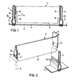
- Fig. 1 einen erfindungsgemäßen Steckteiler im Anschlußzustand an den beiden parallelen Fachwänden einer Schublade' od.dgl., wobei letztere im Vertikalschnitt gezeigt ist;
- Fig. 2 den Steckteiler nach Fig. 1 im gelösten Zustand in perspektivischer Darstellung.
- Fig. 1 shows a plug-in divider according to the invention in the connected state on the two parallel compartment walls of a drawer or the like., The latter in the Verti is shown;
- Fig. 2 shows the plug-in divider according to Fig. 1 in the released state in a perspective view.
In der Zeichnung ist mit 1 ein Aufbewahrungskasten oder eine Schublade od.dgl. mit parallelen Längs- oder Fachwänden 2 und dem Boden 3 der Schublade bezeichnet. Zwischen den Fachwänden 2 befindet sich ein Längsfach 4, welches durch mindestens einen von oben eingesteckten Steckteiler 5 in Querrichtung unterteilt wird. Die Fachwände 2 bestehen aus flachen Hohlprofilen. Bei dem dargestellten Ausführungsbeispiel ist angenommen, daß das Fach 4 ein Zwischenfach ist, welches zwischen zwei äußeren Fächern 6 und 7 liegt.In the drawing, 1 is a storage box or drawer or the like. designated with parallel longitudinal or
Der dargestellte Steckteiler 5 ist einstückig aus Kunststoff gefertigt. Er besteht aus einem flachen Teilerblatt 8, welches an seinen beiden Enden jeweils einen einstückig angeformten Schenkel 9 bzw. 10 trägt, deren Breite beträchtlich größer ist als die Dicke des Teilerblattes 8. Der flache Schenkel 9 ist mit seiner einen vertikalen Längskante am Teilerblatt 8 einstückig befestigt. Er befindet sich demgemäß in L-förmiger Anordnung am Teilerblatt 8. Der andere Schenkel 10 ist in T-Anordnung mit dem Teilerblatt 8 einstückig verbunden, so daß er nach beiden Seiten über das Teilerblatt vorragt. Die beiden Schenkel 9 und 10 sind dabei etwa rechtwinklig zur Ebene des Teilerblattes 8 angeordnet.The illustrated
Während der flache Schenkel 9 ein im wesentlichen starr mit dem Teilerblatt 8 verbundener Stützschenkel ist, wird der andere Schenkel 10 von einer Federzunge gebildet, die in Längsrichtung des Teilerblattes, also in Pfeilrichtung 11 federelastisch auslenkbar ist. Der Schenkel 10 bzw. die ihn bildende Federzunge ist im oberen Endbereich einstückig mit dem Teilerblatt verbunden, so daß er bzw. sie mit dem unteren freien Ende elastisch in Pfeilrichtung 11 auslenkbar ist. Hinter dem federelastischen Schenkel 10 ist ein Schlitz 12 als Freiraum für die elastische Auslenkung des Schenkels ausgeformt. Fig. 2 zeigt, daß sich der als Federzunge ausgebildete Schenkel 10 von oben zu seinem freien Ende hin verbreitert.While the
An beiden Schenkeln 9 und 10 befinden sich jeweils zwei angeformte Nocken 13 bzw. 14 in Parallelanordnung nebeneinander. Die beiden vertikalen Fachwände 2 weisen als Rasterung jeweils eine Lochreihe 15 mit vertikalen Langlöchern auf. Der Steckteiler 5 wird von oben in das Fach 4 eingeführt, wobei der als Federzunge ausgebildete elastische Schenkel ]0 durch die betreffende Fachwand 2 zunächst etwas elastisch zurückgedrückt wird. In der Einbauposition rasten die Nocken 13 und 14 in die entsprechenden Löcher der Lochreihen 15 der Fachwände 2 ein. Die Elastizität des als Federzunge ausgebildeten Schenkels 10 sichert die Rastverbindungen und bewirkt zugleich einen ausreichenden Festsitz des Steckteilers 5 an den Fachwänden 2. Zum Lösen des Steckteilers 5 braucht dieser lediglich an seinem Teilerblatt 8 nach oben gezogen zu werden. Hierbei gleiten die Nocken 13 und 14 aus den Löchern der Lochreihen 15 heraus. Zumindest die an dem elastischen Schenkel 10 angeordneten Nocken 14 weisen gerundete bzw. geneigte Einrast- und Ausrastflächen 16 und 17 auf. Beim Einstecken des Steckteilers 5 in das Fach 4 begünstigen die Einrastflächen 17 das Einrasten der Nocken 14 in die betreffenden Löcher der Lochreihen 15, während die oberen Ausrastflächen 16 das Lösen der Rastverbindungen beim Herausheben des Steckteilers 5 erleichtern. Im Einbauzustand bewirken die Schenkel 9 unq10 eine breitflächige Abstützung des Teilerblattes 8 an den beiden Fachwänden 2.On both
Es besteht die Möglichkeit, beide Schenkel 9 und 10 in T- oder L-Anordnung mit dem Teilerblatt 8 zu verbinden. Im letztgenannten Fall können die Schenkel so am Teilerblatt angeordnet werden, daß der Steckteiler, in Draufsicht, U- oder Z-förmig ausgestaltet ist.It is possible to connect both
Claims (10)
Applications Claiming Priority (2)
| Application Number | Priority Date | Filing Date | Title |
|---|---|---|---|
| DE19853500543 DE3500543A1 (en) | 1985-01-10 | 1985-01-10 | CONNECTOR FOR SUB-DIVIDING DRAWERS AND THE LIKE |
| DE3500543 | 1985-01-10 |
Publications (2)
| Publication Number | Publication Date |
|---|---|
| EP0187201A2 true EP0187201A2 (en) | 1986-07-16 |
| EP0187201A3 EP0187201A3 (en) | 1987-01-14 |
Family
ID=6259507
Family Applications (1)
| Application Number | Title | Priority Date | Filing Date |
|---|---|---|---|
| EP85112219A Withdrawn EP0187201A3 (en) | 1985-01-10 | 1985-09-26 | Insertable partition for subdividing drawers and the like |
Country Status (2)
| Country | Link |
|---|---|
| EP (1) | EP0187201A3 (en) |
| DE (1) | DE3500543A1 (en) |
Cited By (1)
| Publication number | Priority date | Publication date | Assignee | Title |
|---|---|---|---|---|
| EP1845024A1 (en) * | 2006-04-13 | 2007-10-17 | BITO-LAGERTECHNIK BITTMANN GmbH | Compartment division arrangement for dividing the interior of a container |
Families Citing this family (4)
| Publication number | Priority date | Publication date | Assignee | Title |
|---|---|---|---|---|
| DE8808466U1 (en) * | 1988-07-01 | 1988-10-20 | Robert Thoma Gmbh Rotho - Kunststoffwerke, 7800 Freiburg, De | |
| DE8808467U1 (en) * | 1988-07-01 | 1988-10-20 | Robert Thoma Gmbh Rotho - Kunststoffwerke, 7800 Freiburg, De | |
| US5395049A (en) * | 1994-01-24 | 1995-03-07 | Huhn; Ray A. | Box engaging retainer for collectors' cards |
| DE202016103477U1 (en) * | 2016-06-30 | 2017-10-05 | Grass Gmbh | Device for partitioning an interior of a movable furniture part and furniture with such a device |
Citations (4)
| Publication number | Priority date | Publication date | Assignee | Title |
|---|---|---|---|---|
| FR1283923A (en) * | 1960-12-27 | 1962-02-09 | Improvements to boxes with variable compartments | |
| US3497081A (en) * | 1968-02-26 | 1970-02-24 | Field Mfg Corp | Shelf divider mechanisms |
| FR2247179A1 (en) * | 1973-10-11 | 1975-05-09 | Steelcase Inc | |
| DE3211859A1 (en) * | 1982-03-31 | 1983-10-13 | Peter 6550 Bad Kreuznach Seitz | Strip-shaped movable merchandise divider for dividing merchandise on shelves |
Family Cites Families (2)
| Publication number | Priority date | Publication date | Assignee | Title |
|---|---|---|---|---|
| DE7147587U (en) * | 1900-01-01 | Horn J | Long and cross dividers for containers | |
| US2824349A (en) * | 1953-02-06 | 1958-02-25 | Jean Jacques Wiehr | Device for positioning boards at a predetermined angle |
-
1985
- 1985-01-10 DE DE19853500543 patent/DE3500543A1/en not_active Withdrawn
- 1985-09-26 EP EP85112219A patent/EP0187201A3/en not_active Withdrawn
Patent Citations (4)
| Publication number | Priority date | Publication date | Assignee | Title |
|---|---|---|---|---|
| FR1283923A (en) * | 1960-12-27 | 1962-02-09 | Improvements to boxes with variable compartments | |
| US3497081A (en) * | 1968-02-26 | 1970-02-24 | Field Mfg Corp | Shelf divider mechanisms |
| FR2247179A1 (en) * | 1973-10-11 | 1975-05-09 | Steelcase Inc | |
| DE3211859A1 (en) * | 1982-03-31 | 1983-10-13 | Peter 6550 Bad Kreuznach Seitz | Strip-shaped movable merchandise divider for dividing merchandise on shelves |
Cited By (1)
| Publication number | Priority date | Publication date | Assignee | Title |
|---|---|---|---|---|
| EP1845024A1 (en) * | 2006-04-13 | 2007-10-17 | BITO-LAGERTECHNIK BITTMANN GmbH | Compartment division arrangement for dividing the interior of a container |
Also Published As
| Publication number | Publication date |
|---|---|
| EP0187201A3 (en) | 1987-01-14 |
| DE3500543A1 (en) | 1986-07-10 |
Similar Documents
| Publication | Publication Date | Title |
|---|---|---|
| EP2765886B1 (en) | Device for storing utensils, especially tools | |
| DE2927114A1 (en) | SHELVING SYSTEM | |
| DE8106304U1 (en) | STORAGE DEVICE | |
| DE2213024B2 (en) | DISPENSER FOR RAZOR UNITS | |
| DE2644824B2 (en) | Hanging folder | |
| DE1927066B2 (en) | Guide part for printed circuit boards | |
| EP0187201A2 (en) | Insertable partition for subdividing drawers and the like | |
| DE10237138A1 (en) | Storage rack for a refrigerator | |
| DE202020100739U1 (en) | Device for feeding goods | |
| EP0123077A1 (en) | Tool bearing | |
| EP0275894B1 (en) | Filing container for documents standing on edge | |
| AT519456B1 (en) | Device for introducing curtain slides into a guide rail | |
| EP0064754B1 (en) | Holding device for prospectuses and the like flat material | |
| EP0173810A2 (en) | Shelf subdivision with inserting partitions for drawings or the like | |
| EP0063250A2 (en) | Drawer rack for storing small items | |
| DE3314838C2 (en) | ||
| EP0529112B1 (en) | Slide magazine | |
| EP1266371B1 (en) | Device for holding turning plates or the like | |
| AT392441B (en) | LABELING RIDER | |
| DE3700435A1 (en) | Insertable divider for subdividing compartments of drawers and the like, in particular for chemist's shop cabinets | |
| DE19502686C2 (en) | Presentation floor for paper, stationery and office supplies | |
| WO1999047863A1 (en) | Oven rack or baking tray for a baking oven | |
| DE2837683C2 (en) | Storage container open at the top with at least one movable partition | |
| DE2600025C2 (en) | Drawer cabinet | |
| DE3015764A1 (en) | Partition for sheet metal drawer - has projections engaging in base recesses to stand upright and support insert trays |
Legal Events
| Date | Code | Title | Description |
|---|---|---|---|
| PUAI | Public reference made under article 153(3) epc to a published international application that has entered the european phase |
Free format text: ORIGINAL CODE: 0009012 |
|
| AK | Designated contracting states |
Kind code of ref document: A2 Designated state(s): AT BE CH FR IT LI LU NL |
|
| PUAL | Search report despatched |
Free format text: ORIGINAL CODE: 0009013 |
|
| 17P | Request for examination filed |
Effective date: 19861018 |
|
| AK | Designated contracting states |
Kind code of ref document: A3 Designated state(s): AT BE CH FR IT LI LU NL |
|
| STAA | Information on the status of an ep patent application or granted ep patent |
Free format text: STATUS: THE APPLICATION HAS BEEN WITHDRAWN |
|
| 18W | Application withdrawn |
Withdrawal date: 19870207 |
|
| RIN1 | Information on inventor provided before grant (corrected) |
Inventor name: FAHRENBERGER, REINER |