EP0529112B1 - Slide magazine - Google Patents
Slide magazine Download PDFInfo
- Publication number
- EP0529112B1 EP0529112B1 EP91114039A EP91114039A EP0529112B1 EP 0529112 B1 EP0529112 B1 EP 0529112B1 EP 91114039 A EP91114039 A EP 91114039A EP 91114039 A EP91114039 A EP 91114039A EP 0529112 B1 EP0529112 B1 EP 0529112B1
- Authority
- EP
- European Patent Office
- Prior art keywords
- slide
- magazine
- base
- slide magazine
- compartment
- Prior art date
- Legal status (The legal status is an assumption and is not a legal conclusion. Google has not performed a legal analysis and makes no representation as to the accuracy of the status listed.)
- Expired - Lifetime
Links
Images
Classifications
-
- G—PHYSICS
- G03—PHOTOGRAPHY; CINEMATOGRAPHY; ANALOGOUS TECHNIQUES USING WAVES OTHER THAN OPTICAL WAVES; ELECTROGRAPHY; HOLOGRAPHY
- G03B—APPARATUS OR ARRANGEMENTS FOR TAKING PHOTOGRAPHS OR FOR PROJECTING OR VIEWING THEM; APPARATUS OR ARRANGEMENTS EMPLOYING ANALOGOUS TECHNIQUES USING WAVES OTHER THAN OPTICAL WAVES; ACCESSORIES THEREFOR
- G03B21/00—Projectors or projection-type viewers; Accessories therefor
- G03B21/08—Projectors or projection-type viewers; Accessories therefor affording epidiascopic projection
-
- G—PHYSICS
- G03—PHOTOGRAPHY; CINEMATOGRAPHY; ANALOGOUS TECHNIQUES USING WAVES OTHER THAN OPTICAL WAVES; ELECTROGRAPHY; HOLOGRAPHY
- G03B—APPARATUS OR ARRANGEMENTS FOR TAKING PHOTOGRAPHS OR FOR PROJECTING OR VIEWING THEM; APPARATUS OR ARRANGEMENTS EMPLOYING ANALOGOUS TECHNIQUES USING WAVES OTHER THAN OPTICAL WAVES; ACCESSORIES THEREFOR
- G03B23/00—Devices for changing pictures in viewing apparatus or projectors
- G03B23/02—Devices for changing pictures in viewing apparatus or projectors in which a picture is removed from a stock and returned to the same stock or another one; Magazines therefor
- G03B23/04—Devices for changing pictures in viewing apparatus or projectors in which a picture is removed from a stock and returned to the same stock or another one; Magazines therefor with linear movement
- G03B23/044—Devices for changing pictures in viewing apparatus or projectors in which a picture is removed from a stock and returned to the same stock or another one; Magazines therefor with linear movement whereby the picture is returned to the same stock
Definitions
- the invention relates to a slide magazine with a base and with partition walls projecting upwards from the base, which are spaced apart from one another and form compartments for receiving a slide frame each, such as e.g. known from GB-A-2 094 498 ..
- Such slide magazines are only suitable for unilaterally removing slide frames because the dividing walls that delimit the individual compartments for slide frames are connected to one another on one long side of the slide magazine by means of a side wall that extends upwards from the base of the slide magazine, the height of this side wall only is insignificantly lower than the height of each partition above the base.
- the individual partition walls are spaced apart from one another in such a way that the slide magazines are suitable for any slide frames of standardized thickness.
- a significant deficiency of these known slide magazines is that the slide frames are not arranged in a spill-proof manner.
- the invention has for its object to provide a slide magazine of the type mentioned, which are suitable for receiving and storing all conventional slide frames of standardized thickness, the slide frames in the slide magazine can be arranged spill-proof and can be easily removed from the slide magazine.
- the dividing walls have a height adapted to the slide frames and are connected at their end remote from the base to secure a slide frame located in a compartment against falling out by a strip-shaped holding element which extends over the length of the slide magazine extends that each compartment can be equipped or emptied with a slide frame from its two sides, and that at least one resilient holding element is provided on each side of each compartment to secure the slide frame located in a compartment against falling out laterally.
- the corresponding resilient holding element can in this case be provided, for example, on the dividing wall delimiting the corresponding compartment, ie on its two side edges.
- a slide magazine which is easy to produce is obtained if resilient fingers are formed on the base of the two distal end portions of the bottom of each compartment, which project laterally in opposite directions and are formed at their opposite ends with upstanding retaining lugs for holding a corresponding slide frame .
- the two retaining lugs of a compartment are at a distance from one another which corresponds to the length of an edge of the slide frame having a square peripheral edge.
- the resilient fingers By suitably designing the resilient fingers, it is possible to ensure suitable resilience properties, by means of which, even after a long period of use of the slide magazine, a slide holder is securely held in a compartment of the slide magazine between the resilient holding elements or the holding noses which project upward from the resilient fingers the top strip-shaped holding element is given.
- such fingers can be formed relatively easily and, on the other hand, this results in a spring force which is sufficiently large to use the spring fingers or the holding lugs which stand up from them to slide the slide frame located in a compartment against the top-side strip-shaped holding element with such a force press that the corresponding slide frame is prevented from accidentally falling out of the slide magazine, but the slide frame can easily be removed from the slide magazine by the action of a certain force on the corresponding slide frame, as given by the gripping and removal device of a slide projector .
- the slide magazine according to the invention is suitable, due to the appropriate design of its base, both for use in conventional slide projectors in which the slide frames are removed from the slide magazine only on one side, but the slide magazine according to the invention is particularly intended for use in connection with a novel slide projector which has two grips - or removal devices is designed so that slide frames can be removed from the slide magazine both from one side and from the opposite other side and can be arranged again in the slide magazine.
- slide projectors are especially slide projectors with cross-fade technology.
- a symmetrical design of the slide magazine is advantageous in order to minimize the risk of production rejects as a result of uneven shaping or hardening of the plastic material from which such slide magazines are made.
- the top-side strip-shaped holding element extends centrally in the longitudinal direction of the slide magazine and has a width in the transverse direction of the slide magazine that is small in comparison to the transverse dimension of the slide magazine.
- each partition wall in the vicinity of the base of the slide magazine has a transverse dimension corresponding to the base and if each partition wall is tapered towards the top-side strip-shaped retaining element. This results overall in a dimensionally stable slide magazine, which can be loaded from both sides or removed from both sides, and good accessibility to the slide frames.
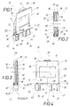
- the figures show an end section of the slide magazine 10 with a few partition walls 12 which stand up from a base 14 of the slide magazine 10.
- a compartment 16 is defined between adjacent partition walls 12 and is suitable for receiving and holding a slide frame 18.
- the base 14 has longitudinal elements 20, 22, 24 and 26, the longitudinal element 24 being designed as a toothed rack for driving the slide magazine 10.
- the partition walls 12 are spaced apart from one another in such a way that the slide magazine 10 is suitable for holding any conventional slide frame 18 with a standardized wall thickness.
- the partition walls 12 have a height which is adapted to the length of the edge of the square slide frame 18.
- the partitions 12 are connected to one another at their end remote from the base 14 by a strip-shaped holding element 28.
- the slide holder 18 located in compartments 16 is prevented from falling out of the slide magazine by the strip-shaped holding element 28.
- FIG. 4 also shows that the slide magazine 10 can be equipped with slide frames 18 from both sides, or that the slide frames 18 can be removed from the slide magazine 10 on both sides.
- a resilient holding element 30 is provided on each side of each compartment 16.
- the resilient holding elements 30 are formed by resilient fingers 32 which protrude laterally from the bottom 34 of each compartment 16 in opposite directions and are formed with holding lugs 36 on their upper side.
- the two retaining lugs 36 of each compartment 16 are at a distance from one another which corresponds to the length of the edge 38 of the square slide frame 18.
- recesses 40 are formed between the longitudinal elements 20 and 22 by means of corresponding shaped slides and recesses 42 laterally next to the longitudinal element.
- recesses 44 are formed in the bottom 34 for shaping the top-side strip-shaped holding element 28, which are caused by the corresponding mold slides of the mold for producing the slide magazine 10.
- FIG. 4 also clearly shows that the resilient fingers 32 have a small length compared to the transverse dimension of the slide magazine 10.
- Figures 1 and 4 further illustrate that each partition 12 in the vicinity of the base 14 has a transverse dimension corresponding to the base 14 and that each partition 12 is tapered toward the top-side strip-shaped holding element 28.
- FIGS. 1 to 4 the same details are each designated with the same reference numbers, so that it is unnecessary to describe all of these details in detail in connection with the individual figures.
Description
Die Erfindung betrifft ein Diamagazin mit einer Basis und mit von der Basis nach oben wegstehenden Trennwänden, die voneinander beabstandet sind und Abteile zur Aufnahme je eines Diarähmchens bilden, wie z.B. aus GB-A-2 094 498 bekannt..The invention relates to a slide magazine with a base and with partition walls projecting upwards from the base, which are spaced apart from one another and form compartments for receiving a slide frame each, such as e.g. known from GB-A-2 094 498 ..
Derartige Diamagazine sind nur zur einseitigen Entnahme von Diarähmchen geeignet, weil die die einzelnen Abteile für Diarähmchen begrenzenden Trennwände auf der einen Längsseite des Diamagazins mittels einer Seitenwand miteinander verbunden sind, die sich von der Basis des Diamagazins nach oben erstreckt, wobei die Höhe dieser Seitenwand nur unwesentlich niedriger ist als die Höhe jeder Trennwand über der Basis. Bei diesen bekannten Diamagazinen weisen die einzelnen Trennwände voneinander einen solchen Abstand auf, dass die Diamagazine für beliebige Diarähmchen genormter Dicke geeignet sind. Ein erheblicher Mangel dieser bekannten Diamagazine besteht darin, dass in ihnen die Diarähmchen nicht verschüttsicher angeordnet sind.Such slide magazines are only suitable for unilaterally removing slide frames because the dividing walls that delimit the individual compartments for slide frames are connected to one another on one long side of the slide magazine by means of a side wall that extends upwards from the base of the slide magazine, the height of this side wall only is insignificantly lower than the height of each partition above the base. In these known slide magazines, the individual partition walls are spaced apart from one another in such a way that the slide magazines are suitable for any slide frames of standardized thickness. A significant deficiency of these known slide magazines is that the slide frames are not arranged in a spill-proof manner.
Der Erfindung liegt die Aufgabe zugrunde, ein Diamagazin der eingangs genannten Art zu schaffen, das zur Aufnahme und Lagerung aller üblichen Diarähmchen genormter Dicke geeignet sind, wobei die Diarähmchen im Diamagazin verschüttsicher anordbar und einfach aus dem Diamagazin entnehmbar sind.The invention has for its object to provide a slide magazine of the type mentioned, which are suitable for receiving and storing all conventional slide frames of standardized thickness, the slide frames in the slide magazine can be arranged spill-proof and can be easily removed from the slide magazine.
Diese Aufgabe wird erfindungsgemäss dadurch gelöst, dass die Trennwände eine an die Diarähmchen angepasste Höhe aufweisen und an ihrem von der Basis entfernten Ende zum Sichern eines in einem Abteil befindlichen Diarähmchens gegen Herausfallen miteinander durch ein streifenförmiges Halteelement verbunden sind, das sich über die Länge des Diamagazins erstreckt, dass jedes Abteil von seinen beiden Seiten mit einem Diarähmchen bestückbar bzw. entleerbar ist, und dass zum Sichern des in einem Abteil befindlichen Diarähmchens gegen seitliches Herausfallen an jeder Seite jedes Abteils mindestens ein federndes Halteelement vorgesehen ist. Das entsprechende federnde Halteelement kann hierbei z.B. an der das entsprechende Abteil begrenzenden Trennwand, d.h. an deren beiden Seitenrändern vorgesehen sein. Ein einfach herzustellendes Diamagazin ergibt sich, wenn an den beiden voneinander entfernten Endabschnitten des Bodens jedes Abteils an der Basis federnde Finger ausgebildet sind, die in entgegengesetzte Richtungen seitlich wegstehen und an ihren voneinander abgewandten Enden mit nach oben stehenden Haltenasen zum Halten eines entsprechenden Diarähmchens ausgebildet sind. Die beiden Haltenasen eines Abteils weisen hierbei voneinander einen Abstand auf, der der Länge einer Randkante des einen quadratischen Umfangsrand besitzenden Diarähmchens entspricht.This object is achieved according to the invention in that the dividing walls have a height adapted to the slide frames and are connected at their end remote from the base to secure a slide frame located in a compartment against falling out by a strip-shaped holding element which extends over the length of the slide magazine extends that each compartment can be equipped or emptied with a slide frame from its two sides, and that at least one resilient holding element is provided on each side of each compartment to secure the slide frame located in a compartment against falling out laterally. The corresponding resilient holding element can in this case be provided, for example, on the dividing wall delimiting the corresponding compartment, ie on its two side edges. A slide magazine which is easy to produce is obtained if resilient fingers are formed on the base of the two distal end portions of the bottom of each compartment, which project laterally in opposite directions and are formed at their opposite ends with upstanding retaining lugs for holding a corresponding slide frame . The two retaining lugs of a compartment are at a distance from one another which corresponds to the length of an edge of the slide frame having a square peripheral edge.
Durch geeignete Ausbildung der federnden Finger ist es möglich, passende Federungseigenschaften zu gewährleisten, durch welche auch nach einer langen Benutzungsdauer des Diamagazins eine sichere Halterung eines Diarähmchens in einem Abteil des Diamagazins zwischen den federnden Halteelementen bzw. den von den federnden Fingern nach oben stehenden Haltenasen und dem oberseitigen streifenförmigen Halteelement gegeben ist. Zum einen sind derartige Finger relativ einfach ausbildbar und zum anderen ergibt sich hierdurch eine ausreichend grosse Federkraft, um mit Hilfe der federnden Finger bzw. der von diesen nach oben stehenden Haltenasen das in einem Abteil befindliche Diarähmchen gegen das oberseitige streifenförmige Halteelement mit einer solchen Kraft zu drücken, dass das entsprechende Diarähmchen an einem ungewollten Herausfallen aus dem Diamagazin gehindert ist, wobei das Diarähmchen jedoch durch Einwirkung einer bestimmten Kraft auf das entsprechende Diarähmchen, wie sie durch die Greif- und Entnahmeeinrichtung eines Diaprojektors gegeben ist, problemlos aus dem Diamagazin entnommen werden kann. Das erfindungsgemässe Diamagazin eignet sich durch passende Ausbildung seiner Basis sowohl zum Einsatz in herkömmlichen Diaprojektoren, bei welchen die Diarähmchen aus dem Diamagazin nur einseitig entnommen werden, das erfindungsgemässe Diamagazin ist jedoch insbes. zur Anwendung in Verbindung mit einem neuartigen Diaprojektor vorgesehen, der mit zwei Greif- bzw. Entnahmeeinrichtungen ausgebildet ist, um Diarähmchen sowohl von der einen als auch von der gegenüberliegenden anderen Seite aus dem Diamagazin entnehmen und wieder im Diamagazin anordnen zu können. Bei diesen Diaprojektoren handelt es sich insbes. um Diaprojektoren mit Überblendtechnik.By suitably designing the resilient fingers, it is possible to ensure suitable resilience properties, by means of which, even after a long period of use of the slide magazine, a slide holder is securely held in a compartment of the slide magazine between the resilient holding elements or the holding noses which project upward from the resilient fingers the top strip-shaped holding element is given. On the one hand, such fingers can be formed relatively easily and, on the other hand, this results in a spring force which is sufficiently large to use the spring fingers or the holding lugs which stand up from them to slide the slide frame located in a compartment against the top-side strip-shaped holding element with such a force press that the corresponding slide frame is prevented from accidentally falling out of the slide magazine, but the slide frame can easily be removed from the slide magazine by the action of a certain force on the corresponding slide frame, as given by the gripping and removal device of a slide projector . The slide magazine according to the invention is suitable, due to the appropriate design of its base, both for use in conventional slide projectors in which the slide frames are removed from the slide magazine only on one side, but the slide magazine according to the invention is particularly intended for use in connection with a novel slide projector which has two grips - or removal devices is designed so that slide frames can be removed from the slide magazine both from one side and from the opposite other side and can be arranged again in the slide magazine. These slide projectors are especially slide projectors with cross-fade technology.
Eine symmetrische Ausbildung des Diamagazins ist vorteilhaft um die Gefahr von Produktionsausschuss infolge ungleichmässiger Formung bzw. Aushärtung des Kunststoffmaterials, aus welchem derartige Diamagazine bestehen, zu minimieren. Zu diesem Zweck ist es vorteilhaft, wenn das oberseitige streifenförmige Halteelement sich mittig in Längsrichtung des Diamagazins erstreckt und in Querrichtung des Diamagazins eine Breite besitzt, die im Vergleich zur Querabmessung des Diamagazins klein ist. Durch eine solche Dimensionierung ist es problemlos möglich, das streifenförmige Halteteil mit entsprechenden Formschiebern im Diamagazin-Formwerkzeug herzustellen, wobei diese Formschieber in der Basis bzw. im Boden jedes Abteils eine entsprechende Aussparung freilassen. Durch diese Aussparungen im Boden jedes Abteils ergibt sich ausserdem nicht nur eine Materialeinsparung sondern gleichzeitig auch eine Gewichtsreduktion des Diamagazins. Demselben Zweck dient es, wenn jede Trennwand in der Nachbarschaft der Basis des Diamagazins eine der Basis entsprechende Querabmessung aufweist und wenn jede Trennwand zum oberseitigen streifenförmigen Rückhalteelement hin verjüngt ist. Dadurch ergibt sich insgesamt ein formstabiles, von beiden Seiten bestückbares bzw. beidseitig entnehmbares Diamagazin und eine gute Zugänglichkeit zu den Diarähmchen.A symmetrical design of the slide magazine is advantageous in order to minimize the risk of production rejects as a result of uneven shaping or hardening of the plastic material from which such slide magazines are made. For this purpose, it is advantageous if the top-side strip-shaped holding element extends centrally in the longitudinal direction of the slide magazine and has a width in the transverse direction of the slide magazine that is small in comparison to the transverse dimension of the slide magazine. Such a dimensioning makes it possible to produce the strip-shaped holding part in the slide magazine molding tool with corresponding mold slides without any problems, these mold slides leaving a corresponding recess in the base or bottom of each compartment. These recesses in the bottom of each compartment also result in not only material savings but also a reduction in weight of the slide magazine. The same purpose is served if each partition wall in the vicinity of the base of the slide magazine has a transverse dimension corresponding to the base and if each partition wall is tapered towards the top-side strip-shaped retaining element. This results overall in a dimensionally stable slide magazine, which can be loaded from both sides or removed from both sides, and good accessibility to the slide frames.
Weitere Einzelheiten, Merkmale und Vorteile ergeben sich aus der nachfolgenden Beschreibung eines in der Zeichnung abschnittweise dargestellten Ausführungsbeispieles des erfindungsgemässen Diamagazins. Es zeigt:
- Fig. 1
- eine räumliche Darstellung eines Endabschnittes des Diamagazins, wobei ein Abteil ohne und das durchgeschnitten gezeichnete Abteil mit einem Diarähmchen gezeichnet ist,
- Fig. 2
- eine Draufsicht auf den Abschnitt des Diamagazins gemäss Fig. 1 in Blickrichtung des Pfeiles II,
- Fig. 3
- eine Ansicht des Abschnittes des Diamagazins gem. Fig. 1 in Blickrichtung des Pfeiles III von der Seite, und
- Fig. 4
- eine Ansicht des durchgeschnitten gezeichneten Endabschnittes des Diamagazins gemäss Fig. 1 in Blickrichtung des Pfeiles IV von vorne.
- Fig. 1
- 3 shows a spatial representation of an end section of the slide magazine, a compartment without and the section drawn with a section being drawn being drawn with a slide frame,
- Fig. 2
- 1 in the viewing direction of arrow II,
- Fig. 3
- a view of the section of the slide magazine acc. Fig. 1 in the direction of arrow III from the side, and
- Fig. 4
- a view of the cut end section of the slide magazine according to FIG. 1 in the direction of arrow IV from the front.
Die Figuren zeigen einen Endabschnitt des Diamagazins 10 mit einigen Trennwänden 12, die von einer Basis 14 des Diamagazins 10 nach oben stehen. Zwischen benachbarten Trennwänden 12 ist jeweils ein Abteil 16 festgelegt, das zur Aufnahme und Halterung eines Diarähmchens 18 geeignet ist.The figures show an end section of the
Die Basis 14 weist Längselemente 20, 22, 24 und 26 auf, wobei das Längselement 24 als Zahnstange zum Antrieb des Diamagazins 10 ausgebildet ist.The
Die Trennwände 12 weisen voneinander einen derartigen Abstand auf, dass das Diamagazin 10 zur Aufnahme jedes beliebigen herkömmlichen Diarähmchens 18 genormter Wanddicke geeignet ist.The
Wie insbes. aus Fig. 4 deutlich ersichtlich ist, weisen die Trennwände 12 eine Höhe auf, die an die Länge der Randkante des quadratischen Diarähmchens 18 angepasst ist. Die Trennwände 12 sind an ihrem von der Basis 14 entfernten Ende miteinander durch ein streifenförmiges Halteelement 28 verbunden. Durch das streifenförmige Halteelement 28 werden die in Abteilen 16 befindlichen Diarähmchen 18 an einem Herausfallen aus dem Diamagazin gehindert. Aus Fig. 4 ist auch ersichtlich, dass das Diamagazin 10 von seinen beiden Seiten mit Diarähmchen 18 bestückbar ist, bzw. dass die Diarähmchen 18 beidseitig aus dem Diamagazin 10 entnehmbar sind. Zum Sichern jedes Diarähmchens 18 gegen ungewolltes seitliches Herausfallen aus dem entsprechenden Abteil 16 des Diamagazins 10 ist an jeder Seite jedes Abteils 16 ein federndes Halteelement 30 vorgesehen. Bei dem in den Figuren gezeichneten Diarähmchen 10 sind die federnden Halteelemente 30 durch federnde Finger 32 gebildet, die vom Boden 34 jedes Abteils 16 in entgegengesetzte Richtungen seitlich wegstehen und an ihrer Oberseite mit Haltenasen 36 ausgebildet sind. Die beiden Haltenasen 36 jedes Abteils 16 weisen voneinander einen Abstand auf, welcher der Länge der Randkante 38 des quadratischen Diarähmchens 18 entspricht.As can be clearly seen in particular from FIG. 4, the
Zur Ausformung der federnden Finger 32 mit den Haltenasen 36 sind zwischen den Längselementen 20 und 22 durch entsprechende Formschieber bedingte Aussparungen 40 und seitlich neben dem Längselement 26 Aussparungen 42 ausgebildet. Entsprechend sind zur Ausformung des oberseitigen streifenförmigen Halteelementes 28 im Boden 34 Aussparungen 44 ausgebildet, die durch die entsprechenden Formschieber des Formwerkzeugs zur Herstellung des Diamagazins 10 bedingt sind.To shape the
Aus Fig. 4 ist ausserdem deutlich ersichtlich, dass die federnden Finger 32 im Vergleich zur Querabmessung des Diamagazins 10 eine kleine Länge besitzen. Die Figuren 1 und 4 verdeutlichen ferner, dass jede Trennwand 12 in der Nachbarschaft der Basis 14 eine der Basis 14 entsprechende Querabmessung aufweist und dass jede Trennwand 12 zum oberseitigen streifenförmigen Halteelement 28 hin verjüngt ausgebildet ist.FIG. 4 also clearly shows that the
In den Figuren 1 bis 4 sind gleiche Einzelheiten jeweils mit denselben Bezugsziffern bezeichnet, so dass es sich erübrigt, alle diese Einzelheiten in Verbindung mit den einzelnen Figuren jeweils detailliert zu beschreiben.In FIGS. 1 to 4, the same details are each designated with the same reference numbers, so that it is unnecessary to describe all of these details in detail in connection with the individual figures.
Claims (4)
- Slide magazine having a base (14) and having partitions (12) which project upwards away from the base (14), are spaced apart, and form compartments (16) for receiving a slide frame (18) in each case, characterized in that the partitions (12) have a height which is adapted to the slide frames (18) and, to secure a slide frame (18) located in a compartment (16) from dropping out, are connected to one another at their end which is remote from the base (14) by means of a strip-shaped holding element (28) which extends over the length of the slide magazine (10); in that each compartment (16) can be loaded with a slide frame (18) or emptied from both its sides; and in that at least one resilient holding element (30) is provided on each side of each compartment (16) to secure the slide frame (18) located in a compartment (16) from dropping out laterally.
- Slide magazine according to Claim 1, characterized in that resilient fingers (32) are formed at the two end sections, remote from one another, of the bottom (34) of each compartment (16) to form the holding elements (30) at the base (14), which fingers project laterally in opposite directions and are formed, at their ends facing away from one another, with upwardly disposed holding lugs (36) for holding a corresponding slide frame (18).
- Slide magazine according to Claim 1, characterized in that the strip-shaped holding element (28) at the top extends centrally in the longitudinal direction of the slide magazine (10) and has a width, in the transverse direction of the slide magazine (10), which is small compared to the transverse dimension of the slide magazine (10).
- Slide magazine according to one of the preceding claims, characterized in that, in the vicinity of the base (14) of the slide magazine (10), each partition (12) has a transverse dimension corresponding to the base (14) and is tapered towards the strip-shaped holding element (28) at the top.
Priority Applications (7)
| Application Number | Priority Date | Filing Date | Title |
|---|---|---|---|
| EP91114039A EP0529112B1 (en) | 1991-08-22 | 1991-08-22 | Slide magazine |
| ES91114039T ES2078401T3 (en) | 1991-08-22 | 1991-08-22 | SLIDE WAREHOUSE. |
| DE59106325T DE59106325D1 (en) | 1991-08-22 | 1991-08-22 | Slide magazine. |
| US07/922,852 US5210556A (en) | 1991-08-22 | 1992-07-31 | Slide magazine |
| KR1019920014382A KR950008350B1 (en) | 1991-08-22 | 1992-08-11 | Slide magzine |
| JP4244201A JPH06342188A (en) | 1991-08-22 | 1992-08-20 | Slide magazine |
| CN92109650A CN1030802C (en) | 1991-08-22 | 1992-08-21 | Slide magazine |
Applications Claiming Priority (1)
| Application Number | Priority Date | Filing Date | Title |
|---|---|---|---|
| EP91114039A EP0529112B1 (en) | 1991-08-22 | 1991-08-22 | Slide magazine |
Publications (2)
| Publication Number | Publication Date |
|---|---|
| EP0529112A1 EP0529112A1 (en) | 1993-03-03 |
| EP0529112B1 true EP0529112B1 (en) | 1995-08-23 |
Family
ID=8207062
Family Applications (1)
| Application Number | Title | Priority Date | Filing Date |
|---|---|---|---|
| EP91114039A Expired - Lifetime EP0529112B1 (en) | 1991-08-22 | 1991-08-22 | Slide magazine |
Country Status (7)
| Country | Link |
|---|---|
| US (1) | US5210556A (en) |
| EP (1) | EP0529112B1 (en) |
| JP (1) | JPH06342188A (en) |
| KR (1) | KR950008350B1 (en) |
| CN (1) | CN1030802C (en) |
| DE (1) | DE59106325D1 (en) |
| ES (1) | ES2078401T3 (en) |
Families Citing this family (1)
| Publication number | Priority date | Publication date | Assignee | Title |
|---|---|---|---|---|
| US5555042A (en) * | 1994-10-06 | 1996-09-10 | Eastman Kodak Company | Apparatus for automatically feeding slides into a film scanner |
Family Cites Families (9)
| Publication number | Priority date | Publication date | Assignee | Title |
|---|---|---|---|---|
| US2931116A (en) * | 1958-03-18 | 1960-04-05 | Bausch & Lomb | Slide projector tray |
| US3416250A (en) * | 1966-03-23 | 1968-12-17 | Airequipt Inc | Metal slide magazine |
| AT273534B (en) * | 1966-06-02 | 1969-08-11 | Meopta Narodni Podnik | Slide changing device for projectors with two essentially parallel axes |
| FR1524772A (en) * | 1967-05-29 | 1968-05-10 | Meopta Narodni Podnik | Method for changing slides in the projection windows of a lantern designed for this purpose, and device for carrying out this method |
| US3532421A (en) * | 1967-12-15 | 1970-10-06 | Airequipt Inc | Modular slide tray |
| DE1901091A1 (en) * | 1969-01-10 | 1970-08-06 | Airequipt Inc | Slide containers consisting of modules |
| US3830566A (en) * | 1972-08-25 | 1974-08-20 | Gaf Corp | Small slide tray |
| FR2489978A1 (en) * | 1980-09-09 | 1982-03-12 | Automatisme Cie Gle | BASKET FOR STORING AND SORTING FILES AND MACHINE FOR READING FILES ARRANGED IN SUCH BASKETS |
| DE3108696C2 (en) * | 1981-03-07 | 1983-05-26 | Ernst Leitz Wetzlar Gmbh, 6330 Wetzlar | Longitudinal magazine |
-
1991
- 1991-08-22 EP EP91114039A patent/EP0529112B1/en not_active Expired - Lifetime
- 1991-08-22 DE DE59106325T patent/DE59106325D1/en not_active Expired - Fee Related
- 1991-08-22 ES ES91114039T patent/ES2078401T3/en not_active Expired - Lifetime
-
1992
- 1992-07-31 US US07/922,852 patent/US5210556A/en not_active Expired - Fee Related
- 1992-08-11 KR KR1019920014382A patent/KR950008350B1/en not_active IP Right Cessation
- 1992-08-20 JP JP4244201A patent/JPH06342188A/en active Pending
- 1992-08-21 CN CN92109650A patent/CN1030802C/en not_active Expired - Fee Related
Also Published As
| Publication number | Publication date |
|---|---|
| DE59106325D1 (en) | 1995-09-28 |
| CN1070747A (en) | 1993-04-07 |
| KR930004799A (en) | 1993-03-23 |
| CN1030802C (en) | 1996-01-24 |
| EP0529112A1 (en) | 1993-03-03 |
| ES2078401T3 (en) | 1995-12-16 |
| KR950008350B1 (en) | 1995-07-27 |
| US5210556A (en) | 1993-05-11 |
| JPH06342188A (en) | 1994-12-13 |
Similar Documents
| Publication | Publication Date | Title |
|---|---|---|
| DE2324755A1 (en) | FRAME TO ACCOMMODATE CONNECTING BOXES FROM PRINTED CIRCUIT CARDS | |
| EP0476343B1 (en) | Box for screwdriver bits | |
| DE2113434C3 (en) | Container for holding and individual dispensing of pencil leads | |
| WO1992000690A1 (en) | Kit for making office desks | |
| DE3421288C2 (en) | Storage containers, in particular for floppy disks | |
| EP0529112B1 (en) | Slide magazine | |
| DE2431462C2 (en) | Dividing organ for drawers | |
| DE3108696C2 (en) | Longitudinal magazine | |
| CH640357A5 (en) | DIAMAGAZINE. | |
| DE2615457A1 (en) | Casette tape storage magazine - has drawer in two halves hingeing together on transverse axis | |
| DE1541194B2 (en) | Dental waste bin and holder | |
| EP0187201A2 (en) | Insertable partition for subdividing drawers and the like | |
| EP0121710A2 (en) | Insert for cash tills | |
| CH640712A5 (en) | Chest of drawers having a housing made of plastic | |
| DE2915981C2 (en) | ||
| DE2847726A1 (en) | CONTAINER IN THE FORM OF A POLYGONAL BOX | |
| DE10013620B4 (en) | Device for holding turning boards or the like. | |
| DE19754960A1 (en) | Stacking basket for retail outlets | |
| DE19842619A1 (en) | General-purpose plastics box for transport and storage is cheap to manufacture, durable and adaptable during manufacture to different types of content | |
| DE659105C (en) | Display and distribution cabinet | |
| DE1759502C3 (en) | Door leaf | |
| DE2600025C2 (en) | Drawer cabinet | |
| EP0873705A2 (en) | Connection of a partition wall by means of a rail for receiving and supporting objects | |
| EP0714622B1 (en) | Chest of drawers with plastic housing | |
| AT221254B (en) | Facility for storing keys |
Legal Events
| Date | Code | Title | Description |
|---|---|---|---|
| PUAI | Public reference made under article 153(3) epc to a published international application that has entered the european phase |
Free format text: ORIGINAL CODE: 0009012 |
|
| AK | Designated contracting states |
Kind code of ref document: A1 Designated state(s): DE ES FR GB IT SE |
|
| 17P | Request for examination filed |
Effective date: 19930629 |
|
| 17Q | First examination report despatched |
Effective date: 19941207 |
|
| GRAA | (expected) grant |
Free format text: ORIGINAL CODE: 0009210 |
|
| AK | Designated contracting states |
Kind code of ref document: B1 Designated state(s): DE ES FR GB IT SE |
|
| REF | Corresponds to: |
Ref document number: 59106325 Country of ref document: DE Date of ref document: 19950928 |
|
| GBT | Gb: translation of ep patent filed (gb section 77(6)(a)/1977) |
Effective date: 19950911 |
|
| ET | Fr: translation filed | ||
| ITF | It: translation for a ep patent filed |
Owner name: STUDIO TORTA SOCIETA' SEMPLICE |
|
| REG | Reference to a national code |
Ref country code: ES Ref legal event code: FG2A Ref document number: 2078401 Country of ref document: ES Kind code of ref document: T3 |
|
| PLBE | No opposition filed within time limit |
Free format text: ORIGINAL CODE: 0009261 |
|
| STAA | Information on the status of an ep patent application or granted ep patent |
Free format text: STATUS: NO OPPOSITION FILED WITHIN TIME LIMIT |
|
| 26N | No opposition filed | ||
| PG25 | Lapsed in a contracting state [announced via postgrant information from national office to epo] |
Ref country code: GB Effective date: 19960822 |
|
| PG25 | Lapsed in a contracting state [announced via postgrant information from national office to epo] |
Ref country code: SE Effective date: 19960823 Ref country code: ES Free format text: THE PATENT HAS BEEN ANNULLED BY A DECISION OF A NATIONAL AUTHORITY Effective date: 19960823 |
|
| GBPC | Gb: european patent ceased through non-payment of renewal fee |
Effective date: 19960822 |
|
| PG25 | Lapsed in a contracting state [announced via postgrant information from national office to epo] |
Ref country code: FR Effective date: 19970430 |
|
| PG25 | Lapsed in a contracting state [announced via postgrant information from national office to epo] |
Ref country code: DE Effective date: 19970501 |
|
| EUG | Se: european patent has lapsed |
Ref document number: 91114039.0 |
|
| REG | Reference to a national code |
Ref country code: FR Ref legal event code: ST |
|
| REG | Reference to a national code |
Ref country code: ES Ref legal event code: FD2A Effective date: 20001204 |
|
| PG25 | Lapsed in a contracting state [announced via postgrant information from national office to epo] |
Ref country code: IT Free format text: LAPSE BECAUSE OF NON-PAYMENT OF DUE FEES;WARNING: LAPSES OF ITALIAN PATENTS WITH EFFECTIVE DATE BEFORE 2007 MAY HAVE OCCURRED AT ANY TIME BEFORE 2007. THE CORRECT EFFECTIVE DATE MAY BE DIFFERENT FROM THE ONE RECORDED. Effective date: 20050822 |