EP0187094B1 - Berührungsloses Wirbelstromprüfverfahren und Vorrichtung zur Durchführung dieses Verfahrens - Google Patents
Berührungsloses Wirbelstromprüfverfahren und Vorrichtung zur Durchführung dieses Verfahrens Download PDFInfo
- Publication number
- EP0187094B1 EP0187094B1 EP85402524A EP85402524A EP0187094B1 EP 0187094 B1 EP0187094 B1 EP 0187094B1 EP 85402524 A EP85402524 A EP 85402524A EP 85402524 A EP85402524 A EP 85402524A EP 0187094 B1 EP0187094 B1 EP 0187094B1
- Authority
- EP
- European Patent Office
- Prior art keywords
- probe
- workpiece
- measurement
- impedance
- monitoring
- Prior art date
- Legal status (The legal status is an assumption and is not a legal conclusion. Google has not performed a legal analysis and makes no representation as to the accuracy of the status listed.)
- Expired
Links
- 238000000034 method Methods 0.000 title claims description 14
- 238000012360 testing method Methods 0.000 title description 2
- 239000000523 sample Substances 0.000 claims description 43
- 238000005259 measurement Methods 0.000 claims description 25
- 238000000926 separation method Methods 0.000 claims description 4
- 238000013519 translation Methods 0.000 claims description 3
- 238000012544 monitoring process Methods 0.000 claims 6
- 230000001105 regulatory effect Effects 0.000 claims 1
- 239000000463 material Substances 0.000 description 5
- 230000003071 parasitic effect Effects 0.000 description 4
- 230000007547 defect Effects 0.000 description 3
- 238000013459 approach Methods 0.000 description 2
- 238000000576 coating method Methods 0.000 description 2
- 238000012937 correction Methods 0.000 description 2
- 230000032798 delamination Effects 0.000 description 2
- 230000000694 effects Effects 0.000 description 2
- 238000007711 solidification Methods 0.000 description 2
- 230000008023 solidification Effects 0.000 description 2
- 241001080024 Telles Species 0.000 description 1
- 239000000919 ceramic Substances 0.000 description 1
- 239000011248 coating agent Substances 0.000 description 1
- 239000002826 coolant Substances 0.000 description 1
- 238000001514 detection method Methods 0.000 description 1
- 230000006866 deterioration Effects 0.000 description 1
- 238000010586 diagram Methods 0.000 description 1
- 239000006185 dispersion Substances 0.000 description 1
- 230000005611 electricity Effects 0.000 description 1
- 238000011156 evaluation Methods 0.000 description 1
- 238000010438 heat treatment Methods 0.000 description 1
- 238000004519 manufacturing process Methods 0.000 description 1
- 238000009659 non-destructive testing Methods 0.000 description 1
- 230000035515 penetration Effects 0.000 description 1
- 230000000737 periodic effect Effects 0.000 description 1
- 230000035699 permeability Effects 0.000 description 1
- 230000010363 phase shift Effects 0.000 description 1
- 230000035939 shock Effects 0.000 description 1
Images
Classifications
-
- G—PHYSICS
- G01—MEASURING; TESTING
- G01N—INVESTIGATING OR ANALYSING MATERIALS BY DETERMINING THEIR CHEMICAL OR PHYSICAL PROPERTIES
- G01N27/00—Investigating or analysing materials by the use of electric, electrochemical, or magnetic means
- G01N27/72—Investigating or analysing materials by the use of electric, electrochemical, or magnetic means by investigating magnetic variables
- G01N27/82—Investigating or analysing materials by the use of electric, electrochemical, or magnetic means by investigating magnetic variables for investigating the presence of flaws
- G01N27/90—Investigating or analysing materials by the use of electric, electrochemical, or magnetic means by investigating magnetic variables for investigating the presence of flaws using eddy currents
- G01N27/9046—Investigating or analysing materials by the use of electric, electrochemical, or magnetic means by investigating magnetic variables for investigating the presence of flaws using eddy currents by analysing electrical signals
- G01N27/9053—Compensating for probe to workpiece spacing
Definitions
- the invention relates to a method and a device for non-destructive testing by eddy currents.
- the eddy current control consists, for example, in supplying a coil mounted on a probe, by a periodic current of given frequency, in presenting the probe on the part to be checked and in analyzing the variations in impedance of the coil caused by eddy currents induced in the room.
- Impedance is a vector with two components, one resistive, the other reactive.
- the eddy current control devices using any two orthonormal axes do not generally make it possible to know the two resistive and reactive axes.
- current devices include a means of adjusting the phase shift of the components, it is thus possible to move the reference frame by rotation; they also include a means of adjustment by translation. The components obtained are therefore deduced from the resistive and reactive components by simple change of reference. Thereafter, only the horizontal component and the vertical component of the impedance will be discussed.
- this value When viewing the value of the impedance of a coil of an absolute type control probe on an oscilloscope, this value is represented by a point. If we approach the probe of a metallic part this point describes a curve which we will call thereafter detachment curve. This curve extends between two extreme points: a point representative of the value of the impedance of the coil called "air”, that is to say when it is sufficiently far from the part to not not undergo its influence and a point representative of the value of the impedance of the coil when the probe is in contact with the workpiece.
- an air gap between the probe and the part due for example to the presence of a coating which does not conduct electricity on the surface of the part or else to a layer of air acts on the length of the curve as a function of its thickness.
- the invention proposes to use the properties of this curve and relates to a method for characterizing the electrically conductive parts according to parameters which have an influence on the separation curve. It can be applied each time the control is carried out by spot measurement on the part and can be extended to control methods where a scan of the surface of the part is carried out.
- Patent DE 3 324 444 provides for making an eddy current measurement without contact between the part and the probe using a differential probe with two coils which fulfills a double function of measuring the delamination on the one hand and of checking the fault. of the room on the other hand.
- This device makes it possible to know at any time the error of measurement of the defect due to the variation of delamination and uses a complex calculation unit to permanently correct this error, during the scanning of the part.
- the present invention also aims to carry out a control without contact between the probe and the part, but by using a measurement probe to a single coil which requires neither error correction calculation means nor differential probe with double coil.
- the abovementioned drawbacks are remedied by positioning the probe, in line with the measurement point on the workpiece at a distance from the surface corresponding to a predetermined value of a first component of the impedance of the coil, the measurement is then performed on the second component.
- the first component is chosen, that which is most influenced by the probe-part distance (see claim 1).
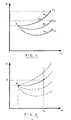
- FIG. 1 represents a bundle of detachment curves for parts of different thicknesses.
- FIG. 2 illustrates the principle of the method according to the invention.
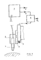
- FIG. 3 gives a schematic representation of the apparatus according to the invention.
- FIG. 1 shows the separation curves obtained for parts of three different thicknesses e l , e 2 , e 3 , these curves converge at point A which corresponds to the value of the impedance of the coil in position distant from the rooms.
- the phase of the recording equipment has been adjusted so that they have an orientation roughly parallel to the horizontal axis.
- oh moves from A to c 1 which is the value of the impedance at the point of contact; for different thicknesses e 1 , e z , e 3 we obtain the curves Ac i , A C2 and Ac 3 .
- Figure 2 shows the principle of the method according to the invention; it is illustrated in an application for measuring the thicknesses of a batch of parts.
- the phase of the eddy current control device is adjusted (this device does not in itself present anything particular), so as to obtain on the oscilloscope a bundle of separation curves for the range of thicknesses concerned. , approximately parallel to one of the two axes.
- This beam is shown in dashed lines and is oriented horizontally in the example chosen.
- the probe is approached substantially normally on the surface of the part in the vicinity of the measurement point at a sufficient distance so that on the screen the point representative of the impedance is at A. This can be achieved by using movement support means automatic preprogrammed.
- the probe is then driven in a translational movement towards the workpiece until the horizontal component H reaches a predetermined value H o .
- H o a predetermined value
- the choice of this first component corresponds to the substantially horizontal orientation of the beam.
- This value H o will have been chosen by a prior test, in order to obtain a significant value of the vertical component for the parts concerned by the measurement.
- FIG. 3 gives a schematic representation of a device allowing the implementation of the method.
- the probe 1 is mounted on a support 2 comprising a carriage 3 movable in translation along a trajectory normal to a part 4 to be checked maintained on a base.
- the devices for prepositioning the part with respect to the probe are not shown in the diagram because they are not part of the invention, they can be manual or automatic with programmed drive means.
- the carriage 3 is driven by a motor 5, for example an electric motor, which receives a control signal from a control system 6 known per se.
- the box of the system 6 comprises a means making it possible to display a reference value H o and an input for a signal H. This system has the function of comparing H to H o and controlling the supply of the motor until the two values become equal.
- the signal H corresponds to one of the components, for example horizontal, of the impedance of the coil, delivered by the control device 7 by eddy currents.
- This device 7 is also a commercial device; its function is in particular to power the probe, to analyze the variations of im pedance and deliver two signals H and V representative of its components.
- the invention is not limited to the embodiment shown; it includes all the equivalents within the reach of those skilled in the art.
- the application is not limited to the measurement of thicknesses.
Landscapes
- Chemical & Material Sciences (AREA)
- Analytical Chemistry (AREA)
- Electrochemistry (AREA)
- Physics & Mathematics (AREA)
- Health & Medical Sciences (AREA)
- Life Sciences & Earth Sciences (AREA)
- Chemical Kinetics & Catalysis (AREA)
- Biochemistry (AREA)
- General Health & Medical Sciences (AREA)
- General Physics & Mathematics (AREA)
- Immunology (AREA)
- Pathology (AREA)
- Investigating Or Analyzing Materials By The Use Of Magnetic Means (AREA)
- Measurement Of Length, Angles, Or The Like Using Electric Or Magnetic Means (AREA)
Claims (4)
Applications Claiming Priority (2)
| Application Number | Priority Date | Filing Date | Title |
|---|---|---|---|
| FR8419409A FR2574938B1 (fr) | 1984-12-19 | 1984-12-19 | Methode de controle par courants de foucault sans contact et dispositif de mise en oeuvre |
| FR8419409 | 1984-12-19 |
Publications (3)
| Publication Number | Publication Date |
|---|---|
| EP0187094A1 EP0187094A1 (de) | 1986-07-09 |
| EP0187094B1 true EP0187094B1 (de) | 1988-10-26 |
| EP0187094B2 EP0187094B2 (de) | 1992-05-13 |
Family
ID=9310756
Family Applications (1)
| Application Number | Title | Priority Date | Filing Date |
|---|---|---|---|
| EP85402524A Expired - Lifetime EP0187094B2 (de) | 1984-12-19 | 1985-12-18 | Berührungsloses Wirbelstromprüfverfahren und Vorrichtung zur Durchführung dieses Verfahrens |
Country Status (4)
| Country | Link |
|---|---|
| US (1) | US4727322A (de) |
| EP (1) | EP0187094B2 (de) |
| DE (1) | DE3565895D1 (de) |
| FR (1) | FR2574938B1 (de) |
Families Citing this family (37)
| Publication number | Priority date | Publication date | Assignee | Title |
|---|---|---|---|---|
| DE3686330T2 (de) * | 1985-12-28 | 1993-02-18 | Yamaha Corp | Kontaktloser markierungssensor. |
| GB8622702D0 (en) * | 1986-09-20 | 1986-10-29 | Ford Motor Co | Measuring coating thickness |
| US4849693A (en) * | 1988-02-29 | 1989-07-18 | Battelle Memorial Institute | Automated measurement system employing eddy currents to adjust probe position and determine metal hardness |
| US5200704A (en) * | 1991-02-28 | 1993-04-06 | Westinghouse Electric Corp. | System and method including a buried flexible sheet target impregnated with ferromagnetic particles and eddy current probe for determining proximity of a non-conductive underground structure |
| ES2108728T3 (es) * | 1991-03-13 | 1998-01-01 | Westinghouse Electric Corp | Procedimiento para determinar la magnitud de la deformacion inducida en un material en respuesta a una fuerza de compresion. |
| US5223793A (en) * | 1991-04-29 | 1993-06-29 | Intex Inc. | Apparatus for controlled rotation of a sphere or ball for inspecting or marking the surface with a predetermined pattern |
| US5394084A (en) * | 1991-12-23 | 1995-02-28 | The Boeing Company | Method and apparatus for reducing errors in eddy-current conductivity measurements due to lift-off by interpolating between a plurality of reference conductivity measurements |
| US5420507A (en) * | 1992-09-28 | 1995-05-30 | Edward L. Laskowski | Method and apparatus for sensing a target characteristic by measuring both impedance and resonant frequency of a tank circuit |
| US5552704A (en) * | 1993-06-25 | 1996-09-03 | Tencor Instruments | Eddy current test method and apparatus for measuring conductance by determining intersection of lift-off and selected curves |
| US5541510A (en) * | 1995-04-06 | 1996-07-30 | Kaman Instrumentation Corporation | Multi-Parameter eddy current measuring system with parameter compensation technical field |
| US6285183B1 (en) | 1996-09-30 | 2001-09-04 | Mcdonnell Douglas Corporation | Method and system for measuring the volume loss of a metal substrate |
| DE19860487A1 (de) * | 1998-12-28 | 2000-07-06 | Siemens Ag | Verfahren und Vorrichtung zur räumlichen Vermessung einer Inhomogenität an einer Oberfläche eines Kernreaktorbauteils und Anwendung des Verfahrens zur Vermessung einer elektrisch praktisch nicht leitenden Schicht |
| US6346807B1 (en) * | 1999-10-22 | 2002-02-12 | Bently Nevada Corporation | Digital eddy current proximity system: apparatus and method |
| RU2190845C2 (ru) * | 1999-12-16 | 2002-10-10 | Общество с ограниченной ответственностью "Петролазер" | Вихретоковый дефектоскоп |
| JP3758439B2 (ja) * | 1999-12-20 | 2006-03-22 | 日本精工株式会社 | 曲面を有する被検査体の欠陥を曲面に沿って非接触で検出する方法 |
| SE520322C2 (sv) | 2000-03-23 | 2003-06-24 | Daprox Ab | Sätt och anordning för avståndsbestämning mellan en stator och en denna motstående roterande rotor |
| TWI241398B (en) * | 2000-03-28 | 2005-10-11 | Toshiba Corp | Eddy current loss measuring sensor, film thickness measuring device, film thickness measuring method and recording medium |
| US6549006B2 (en) | 2000-04-07 | 2003-04-15 | Cuong Duy Le | Eddy current measurements of thin-film metal coatings using a selectable calibration standard |
| US6741076B2 (en) | 2000-04-07 | 2004-05-25 | Cuong Duy Le | Eddy current measuring system for monitoring and controlling a CMP process |
| US20030210041A1 (en) * | 2000-04-07 | 2003-11-13 | Le Cuong Duy | Eddy current measuring system for monitoring and controlling a chemical vapor deposition (CVD) process |
| US6762604B2 (en) | 2000-04-07 | 2004-07-13 | Cuong Duy Le | Standalone eddy current measuring system for thickness estimation of conductive films |
| US6407546B1 (en) * | 2000-04-07 | 2002-06-18 | Cuong Duy Le | Non-contact technique for using an eddy current probe for measuring the thickness of metal layers disposed on semi-conductor wafer products |
| US6593737B2 (en) | 2000-08-24 | 2003-07-15 | Shell Oil Company | Method for measuring the wall thickness of an electrically conductive object |
| JP2002148012A (ja) * | 2000-11-08 | 2002-05-22 | Ulvac Japan Ltd | 膜厚測定装置及び膜厚測定方法 |
| US6933718B2 (en) * | 2001-06-12 | 2005-08-23 | The Boeing Company | Quantification method and system for corrosion and damage assessment |
| US7215117B2 (en) | 2001-10-17 | 2007-05-08 | Esr Technology Ltd. | Measurement with a magnetic field |
| GB0124910D0 (en) | 2001-10-17 | 2001-12-05 | Accentus Plc | Measurement of material properties |
| US20040207395A1 (en) * | 2002-04-08 | 2004-10-21 | Moshe Sarfaty | Eddy current-capacitance sensor for conducting film characterization |
| JP4451111B2 (ja) * | 2003-10-20 | 2010-04-14 | 株式会社荏原製作所 | 渦電流センサ |
| US7295003B2 (en) * | 2004-09-22 | 2007-11-13 | The Boeing Company | Non-destructive testing system and method utilizing a magnetic field to identify defects in a layer of a laminated material |
| US7830140B2 (en) * | 2007-08-07 | 2010-11-09 | General Electric Company | Eddy current system and method for estimating material properties of parts |
| FI20085456A7 (fi) * | 2008-05-15 | 2009-11-16 | Valtion Teknillinen Tutkimuskeskus | Menetelmä ja laitteisto sähköisen koodin tunnistamiseksi |
| GB0820930D0 (en) * | 2008-11-17 | 2008-12-24 | Dvs Techology Ltd | Coating thickness measurement |
| US20130249540A1 (en) * | 2012-03-22 | 2013-09-26 | Olympus Ndt Inc. | Eddy current array probe and method for lift-off compensation during operation without known lift references |
| US9335151B2 (en) | 2012-10-26 | 2016-05-10 | Applied Materials, Inc. | Film measurement |
| CN106404899A (zh) * | 2016-08-29 | 2017-02-15 | 爱德森(厦门)电子有限公司 | 一种涡流检测提离晃动补偿方法 |
| CN116086300B (zh) * | 2023-04-07 | 2023-06-09 | 苏州中科科仪技术发展有限公司 | 一种磁悬浮分子泵位移传感器的校准方法及其应用 |
Family Cites Families (12)
| Publication number | Priority date | Publication date | Assignee | Title |
|---|---|---|---|---|
| US3358225A (en) * | 1964-03-27 | 1967-12-12 | Richard S Peugeot | Lift-off compensation for eddy current testers |
| GB1130870A (en) * | 1966-10-20 | 1968-10-16 | Nat Res Dev | Method and apparatus for detecting and measuring cracks in metal structures |
| US3718855A (en) * | 1970-11-30 | 1973-02-27 | R Cordova | Eddy current flaw detection system |
| JPS5376926A (en) * | 1976-12-21 | 1978-07-07 | Nippon Kokan Kk | Molten metal level monitor controller of continuous casting machine that use eddy flow system range finder for measurement of molten metal level |
| DE2815228C3 (de) * | 1978-04-08 | 1980-11-27 | Institut Dr. Friedrich Foerster Pruefgeraetebau, 7410 Reutlingen | Prüfanordnung für die zerstörungsfreie Prüfung von metallischem Prüfgut |
| US4215310A (en) * | 1978-07-10 | 1980-07-29 | United States Steel Corporation | Magnetic testing method and apparatus having provision for eliminating inaccuracies caused by gaps between probe and test piece |
| US4438754A (en) * | 1979-08-14 | 1984-03-27 | Shell Oil Company | Method for sensing and remotely controlling a tool to workpiece spatial relationship |
| CA1158314A (en) * | 1980-08-18 | 1983-12-06 | Majesty (Her) In Right Of Canada As Represented By Atomic Energy Of Cana Da Limited | Eddy current surface probe |
| JPS57178155A (en) * | 1981-04-27 | 1982-11-02 | Hitachi Ltd | Eddy current test equipment |
| US4596953A (en) * | 1982-04-14 | 1986-06-24 | Daidotokushuko Kabushikikaisha | Apparatus for scanning a material for detection of flaws and having material axis deviation detection |
| US4641092A (en) * | 1982-07-08 | 1987-02-03 | Sumitomo Metal Industries, Ltd. | Rotary probe apparatus for detecting flaws in a test object |
| US4644274A (en) * | 1983-04-01 | 1987-02-17 | General Electric Company | Apparatus for supporting an eddy current probe used to scan an irregular surface |
-
1984
- 1984-12-19 FR FR8419409A patent/FR2574938B1/fr not_active Expired
-
1985
- 1985-12-17 US US06/809,785 patent/US4727322A/en not_active Expired - Lifetime
- 1985-12-18 DE DE8585402524T patent/DE3565895D1/de not_active Expired
- 1985-12-18 EP EP85402524A patent/EP0187094B2/de not_active Expired - Lifetime
Also Published As
| Publication number | Publication date |
|---|---|
| FR2574938B1 (fr) | 1986-12-26 |
| DE3565895D1 (en) | 1988-12-01 |
| EP0187094A1 (de) | 1986-07-09 |
| FR2574938A1 (fr) | 1986-06-20 |
| EP0187094B2 (de) | 1992-05-13 |
| US4727322A (en) | 1988-02-23 |
Similar Documents
| Publication | Publication Date | Title |
|---|---|---|
| EP0187094B1 (de) | Berührungsloses Wirbelstromprüfverfahren und Vorrichtung zur Durchführung dieses Verfahrens | |
| FR2602053A1 (fr) | Dispositif et procede d'essais non destructifs d'une piece par la mesure de l'impedance de courants de foucault | |
| WO2010070125A1 (fr) | Dispositif de regulation d'un anemometre à fil | |
| EP0146091B1 (de) | Verfahren und System zur zerstörungsfreien Prüfung durch Wirbelströme unter Verwendung von überstreichenden Frequenzen | |
| WO2011151530A1 (fr) | Procede et dispositif de mesure de l'epaisseur d'une couche de revetement sur une bande en defilement | |
| EP0435757B1 (de) | Verfahren und Vorrichtung zur gleichzeitigen Messung des Abstandes zwischen metallischen Tuben und der Oxyde-Dicke auf den Tuben | |
| FR2548351A1 (fr) | Procede et appareillage de mesure sans contact d'une coquille solidifiee d'une piece metallique coulee | |
| FR2513753A1 (fr) | Sonde profilometrique pour la verification interne des tubes | |
| CN111266583A (zh) | 一种金属增材制造的在线检测系统和金属增材制造装置 | |
| FR2558599A1 (fr) | Procede et dispositif de compensation automatique des erreurs mecaniques d'un gradientmetre magnetique | |
| EP0290513B1 (de) | Verfahren zum feststellen der variationen der wandstärke eines elektrisch leitenden körpers | |
| KR101158781B1 (ko) | 초전도 코일 테스트 | |
| FR2743148A1 (fr) | Dispositif et procede de controle de tubes par courants de foucault | |
| EP0021893A1 (de) | Verfahren und Vorrichtung zur Wirbelstromprüfung metallischer Produkte und Anwendung der Vorrichtung und des Verfahrens | |
| US6414480B1 (en) | Method and system for eddy current inspection calibration | |
| US7388369B2 (en) | Method and apparatus for measuring hydrogen concentration in zirconium alloy components in the fuel pool of a nuclear power plant | |
| JP4157597B2 (ja) | ウエハのシリコン層の探傷装置及び探傷方法 | |
| JPH05149927A (ja) | 導電膜検査方法およびその装置 | |
| EP0061956B1 (de) | Verfahren zur wirbelstromzerstörungsfreien Prüfung unabhängig von dem Abstand der Sonden relativ zu dem Probenstück und Vorrichtung zur Ausübung des Verfahrens | |
| EP0736173B1 (de) | Verfahren und vorrichtung zur magnetischen kontrolle metallischer produkte | |
| FR2689637A1 (fr) | Procédé et installation de contrôle non destructif d'une pièce utilisant un capteur à courants de foucault. | |
| CN109967910A (zh) | 焊接熔深在线检测装置及方法 | |
| EP3710816A1 (de) | Verfahren zur charakterisierung und überwachung der homogenität von durch lasersintern hergestellten metallteilen | |
| FR2531537A1 (fr) | Procede et appareil pour la detection de defauts par courants de foucault | |
| EP2368126B1 (de) | Anemometersonde und herstellungsverfahren |
Legal Events
| Date | Code | Title | Description |
|---|---|---|---|
| PUAI | Public reference made under article 153(3) epc to a published international application that has entered the european phase |
Free format text: ORIGINAL CODE: 0009012 |
|
| 17P | Request for examination filed |
Effective date: 19860116 |
|
| AK | Designated contracting states |
Kind code of ref document: A1 Designated state(s): BE CH DE FR GB IT LI NL SE |
|
| 17Q | First examination report despatched |
Effective date: 19880330 |
|
| ITF | It: translation for a ep patent filed | ||
| GRAA | (expected) grant |
Free format text: ORIGINAL CODE: 0009210 |
|
| AK | Designated contracting states |
Kind code of ref document: B1 Designated state(s): BE CH DE FR GB IT LI NL SE |
|
| GBT | Gb: translation of ep patent filed (gb section 77(6)(a)/1977) | ||
| REF | Corresponds to: |
Ref document number: 3565895 Country of ref document: DE Date of ref document: 19881201 |
|
| PLBI | Opposition filed |
Free format text: ORIGINAL CODE: 0009260 |
|
| 26 | Opposition filed |
Opponent name: ASEA BROWN BOVERI AB Effective date: 19890718 |
|
| NLR1 | Nl: opposition has been filed with the epo |
Opponent name: ASEA BROWN BOVERI AB |
|
| ITTA | It: last paid annual fee | ||
| PUAH | Patent maintained in amended form |
Free format text: ORIGINAL CODE: 0009272 |
|
| STAA | Information on the status of an ep patent application or granted ep patent |
Free format text: STATUS: PATENT MAINTAINED AS AMENDED |
|
| 27A | Patent maintained in amended form |
Effective date: 19920513 |
|
| AK | Designated contracting states |
Kind code of ref document: B2 Designated state(s): BE CH DE FR GB IT LI NL SE |
|
| REG | Reference to a national code |
Ref country code: CH Ref legal event code: AEN |
|
| ITF | It: translation for a ep patent filed | ||
| NLR3 | Nl: receipt of modified translations in the netherlands language after an opposition procedure | ||
| NLR2 | Nl: decision of opposition | ||
| REG | Reference to a national code |
Ref country code: GB Ref legal event code: 777B |
|
| GBTA | Gb: translation of amended ep patent filed (gb section 77(6)(b)/1977) |
Effective date: 19930316 |
|
| EAL | Se: european patent in force in sweden |
Ref document number: 85402524.4 |
|
| REG | Reference to a national code |
Ref country code: GB Ref legal event code: IF02 |
|
| REG | Reference to a national code |
Ref country code: FR Ref legal event code: TP Ref country code: FR Ref legal event code: CD |
|
| PGFP | Annual fee paid to national office [announced via postgrant information from national office to epo] |
Ref country code: SE Payment date: 20031125 Year of fee payment: 19 Ref country code: CH Payment date: 20031125 Year of fee payment: 19 |
|
| PGFP | Annual fee paid to national office [announced via postgrant information from national office to epo] |
Ref country code: NL Payment date: 20031126 Year of fee payment: 19 |
|
| PGFP | Annual fee paid to national office [announced via postgrant information from national office to epo] |
Ref country code: GB Payment date: 20031127 Year of fee payment: 19 Ref country code: FR Payment date: 20031127 Year of fee payment: 19 |
|
| PGFP | Annual fee paid to national office [announced via postgrant information from national office to epo] |
Ref country code: BE Payment date: 20031128 Year of fee payment: 19 |
|
| PGFP | Annual fee paid to national office [announced via postgrant information from national office to epo] |
Ref country code: DE Payment date: 20031210 Year of fee payment: 19 |
|
| PG25 | Lapsed in a contracting state [announced via postgrant information from national office to epo] |
Ref country code: GB Free format text: LAPSE BECAUSE OF NON-PAYMENT OF DUE FEES Effective date: 20041218 |
|
| PG25 | Lapsed in a contracting state [announced via postgrant information from national office to epo] |
Ref country code: SE Free format text: LAPSE BECAUSE OF NON-PAYMENT OF DUE FEES Effective date: 20041219 |
|
| PG25 | Lapsed in a contracting state [announced via postgrant information from national office to epo] |
Ref country code: LI Free format text: LAPSE BECAUSE OF NON-PAYMENT OF DUE FEES Effective date: 20041231 Ref country code: CH Free format text: LAPSE BECAUSE OF NON-PAYMENT OF DUE FEES Effective date: 20041231 Ref country code: BE Free format text: LAPSE BECAUSE OF NON-PAYMENT OF DUE FEES Effective date: 20041231 |
|
| BERE | Be: lapsed |
Owner name: SOC. NATIONALE D'ETUDE ET DE CONSTRUCTION DE MOTEU Effective date: 20041231 |
|
| PG25 | Lapsed in a contracting state [announced via postgrant information from national office to epo] |
Ref country code: NL Free format text: LAPSE BECAUSE OF NON-PAYMENT OF DUE FEES Effective date: 20050701 Ref country code: DE Free format text: LAPSE BECAUSE OF NON-PAYMENT OF DUE FEES Effective date: 20050701 |
|
| EUG | Se: european patent has lapsed | ||
| GBPC | Gb: european patent ceased through non-payment of renewal fee |
Effective date: 20041218 |
|
| REG | Reference to a national code |
Ref country code: CH Ref legal event code: PL |
|
| PG25 | Lapsed in a contracting state [announced via postgrant information from national office to epo] |
Ref country code: FR Free format text: LAPSE BECAUSE OF NON-PAYMENT OF DUE FEES Effective date: 20050831 |
|
| NLV4 | Nl: lapsed or anulled due to non-payment of the annual fee |
Effective date: 20050701 |
|
| REG | Reference to a national code |
Ref country code: FR Ref legal event code: ST |
|
| BERE | Be: lapsed |
Owner name: SOC. NATIONALE D'ETUDE ET DE CONSTRUCTION DE MOTEU Effective date: 20041231 |