EP0187069B1 - Einrichtung und Verfahren zur Steuerung von gelenkten Fahrzeugen - Google Patents
Einrichtung und Verfahren zur Steuerung von gelenkten Fahrzeugen Download PDFInfo
- Publication number
- EP0187069B1 EP0187069B1 EP85402315A EP85402315A EP0187069B1 EP 0187069 B1 EP0187069 B1 EP 0187069B1 EP 85402315 A EP85402315 A EP 85402315A EP 85402315 A EP85402315 A EP 85402315A EP 0187069 B1 EP0187069 B1 EP 0187069B1
- Authority
- EP
- European Patent Office
- Prior art keywords
- beacons
- transmission
- control
- reception
- vehicle
- Prior art date
- Legal status (The legal status is an assumption and is not a legal conclusion. Google has not performed a legal analysis and makes no representation as to the accuracy of the status listed.)
- Expired - Lifetime
Links
- 238000000034 method Methods 0.000 title claims abstract description 7
- 230000010287 polarization Effects 0.000 claims abstract description 18
- 230000005540 biological transmission Effects 0.000 claims abstract description 10
- 238000001514 detection method Methods 0.000 claims abstract description 10
- 230000005855 radiation Effects 0.000 claims abstract description 10
- 230000000694 effects Effects 0.000 claims abstract description 6
- 239000002184 metal Substances 0.000 claims description 4
- 238000003491 array Methods 0.000 claims 1
- 238000009434 installation Methods 0.000 claims 1
- 230000010363 phase shift Effects 0.000 claims 1
- 230000001939 inductive effect Effects 0.000 abstract 1
- 238000000926 separation method Methods 0.000 abstract 1
- 230000000712 assembly Effects 0.000 description 5
- 238000000429 assembly Methods 0.000 description 5
- 230000008878 coupling Effects 0.000 description 4
- 238000010168 coupling process Methods 0.000 description 4
- 238000005859 coupling reaction Methods 0.000 description 4
- 230000011664 signaling Effects 0.000 description 4
- 238000010586 diagram Methods 0.000 description 3
- 230000003071 parasitic effect Effects 0.000 description 3
- 230000006978 adaptation Effects 0.000 description 2
- 230000015572 biosynthetic process Effects 0.000 description 1
- 238000002592 echocardiography Methods 0.000 description 1
- 230000005670 electromagnetic radiation Effects 0.000 description 1
- 238000002513 implantation Methods 0.000 description 1
- 239000000463 material Substances 0.000 description 1
- 238000003786 synthesis reaction Methods 0.000 description 1
- 229910000859 α-Fe Inorganic materials 0.000 description 1
Images


Classifications
-
- B—PERFORMING OPERATIONS; TRANSPORTING
- B61—RAILWAYS
- B61L—GUIDING RAILWAY TRAFFIC; ENSURING THE SAFETY OF RAILWAY TRAFFIC
- B61L3/00—Devices along the route for controlling devices on the vehicle or train, e.g. to release brake or to operate a warning signal
- B61L3/02—Devices along the route for controlling devices on the vehicle or train, e.g. to release brake or to operate a warning signal at selected places along the route, e.g. intermittent control simultaneous mechanical and electrical control
- B61L3/08—Devices along the route for controlling devices on the vehicle or train, e.g. to release brake or to operate a warning signal at selected places along the route, e.g. intermittent control simultaneous mechanical and electrical control controlling electrically
- B61L3/12—Devices along the route for controlling devices on the vehicle or train, e.g. to release brake or to operate a warning signal at selected places along the route, e.g. intermittent control simultaneous mechanical and electrical control controlling electrically using magnetic or electrostatic induction; using radio waves
- B61L3/125—Devices along the route for controlling devices on the vehicle or train, e.g. to release brake or to operate a warning signal at selected places along the route, e.g. intermittent control simultaneous mechanical and electrical control controlling electrically using magnetic or electrostatic induction; using radio waves using short-range radio transmission
Definitions
- the present invention mainly relates to a control device for guided vehicles, for example for trains as well as a method of their automatic piloting.
- Driving a guide vehicle requires knowledge of a great deal of information. Some of this information is linked to the geographic location of the vehicle. Thus, for example, a portion of the track corresponds to an optimal speed of the train.
- Patent FR-2 131 832 describes a train control device by reflection of electromagnetic energy on beacons placed on the track.
- US Patent 3,426,349 describes the use of transponders placed on railroad tracks to control trains.
- the device which is the subject of the present invention comprises signaling devices distributed along the path that the vehicle has to travel, as well as means for detecting said signaling devices.
- the detection means can be coupled to automatic processing means controlling for example the speed of the train, the opening or closing of the doors, the switching on or off of the lights or the voice synthesis of a message.
- the signaling means are passive beacons capable of returning a characteristic signal when they are illuminated by a beam of microwave energy.
- the detection means of the signaling means are for example low power radars.
- the main object of the invention is a device for controlling a guided vehicle comprising beacons reflecting electromagnetic waves, fixed on the path to be covered and means for detecting said beacons which are fixed on said vehicle and which comprise a device for transmission-reception of electromagnetic waves comprising a transmission antenna and a reception antenna characterized in that the radiation axis of the transmission antenna has a non-zero angle with the plane normal to the speed vector of the vehicle and that the beacons are retrodirectives, and a method implementing such a device.
- FIGS. 1 to 8 the same references have been used to designate the same elements.
- Track 1 is equipped with two sets, 2 and 3, of passive beacons 4.
- the beacons constituting a set 2 or 3, are all placed at a same distance from the rails.
- the floors are equipped with means for detecting the beacons 4 at the spacings corresponding to the locations of these beacons.
- FIG. 1 only two sets of beacons 2 and 3 are shown, it being understood that a larger number of set of beacons can be used, determined by the amount of information to be transmitted to the train.
- the sets 2, 3 of tags 4 are doubled, placed symmetrically with respect to the axis of the path that the vehicle has to travel. It is thus possible, for example, to program a different speed for each direction of traffic.
- the tags 4 of the assembly 2 are for example intended to regulate the speed of a train.
- large distance between the beacons 4 ensures great speed of the train.
- the tightening of the beacons controls the slowing of the train.
- the tags 4 of the assembly 3 control, for example, a train stop.
- the taking into account of the tags belonging to the set 2, to the set 3 or to the sets 2 and 3 is controlled for example by an electrical signal circulating in the rail.
- a first embodiment of the device according to the invention comprising two antennas 6 inclined at an angle ⁇ relative to the plane 42.
- the plane 42 is a plane normal to the speed vector of the vehicle 43 In the case where the vehicle 43 moves horizontally the plane 42 is vertical.
- the antennas 6 are fixed to the train 43.
- the tag 4 is made integral with the ground 5, for example between the rails, not shown.
- the electromagnetic waves are emitted by the transmitting antenna follow the axis 8 of said antenna and are reflected by the beacon 4 along the axis 9 of the receiving antenna.
- the use of a transmitting antenna and a separate antenna for reception makes it possible to obtain a good decoupling of the transmitted signal from the received signal.
- the beacon 4 is equipped with means making it possible to rotate the plane of polarization by 90 °.
- a device is for example constituted by a lattice of metal wires embedded in plastic material placed in front of a reflective metal plate.
- the echoes reflected by such a beacon will have a polarization orthogonal to the polarization emitted.
- the radiation reflected by the ground will mainly have the same polarization as the radiation emitted.
- FIG. 3 one can see an embodiment of the device according to the invention comprising a single transmit-receive antenna 6 placed vertically above a beacon 4 ensuring the rotation of the polarization of the emitted radiation.
- the tag 4 has for example the same structure as the tag 4 of FIG. 2.
- the tag 4 comprises two metal plates forming a dihedral. It is well known to those skilled in the art that a dihedral causes the polarization rotation of the electromagnetic radiation received. The dihedral edge is contained in the bisector plane with respect to the polarization planes.
- FIG. 4 one can see a device according to the present invention comprising a single transmit-receive antenna 6 inclined at an angle 8 relative to the plane 42.
- the beacon 4 comprises a reflective plane placed perpendicular to the axis 8 of the antenna 6.
- the Doppler frequency f e is given by the formula: where v is the train speed and the wavelength used. To do this, it suffices to demodulate the signal received by the signal of the same frequency as the transmitted signal and to filter by a high-pass filter.
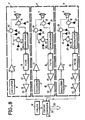
- FIG. 8 Such an exemplary embodiment is illustrated in FIG. 8.
- the ratio (signal / parasitic echo) is improved by the use of an inclined beam associated with a retrodirective beacon 4.
- the signals reflected by the ground in the absence of a beacon take a direction 48 different from the axis 8 of the antenna 6.
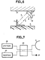
- an exemplary embodiment of the device according to the invention can be seen comprising a transmitting antenna 6 and a receiving antenna 6 inclined at an angle 8 relative to the plane 42, associated with a retrodirective plate 4.
- FIG. 6 one can see an embodiment of the device according to the invention comprising a single transmit-receive antenna 6 inclined at an angle 6 relative to the plane 42, associated with a retrodirective beacon 4.
- the tag 4 ensures the polarization rotation of the waves received.
- the use of the polarization rotation associated with the use of the Doppler effect makes it possible to obtain a very good decoupling of transmission signals with respect to the reception signals.
- the use of the single antenna makes it possible to reduce the cost and the bulk of the system.
- the edge of the dihedral forming a beacon 4 is advantageously not parallel to the plane of the ground 5.
- the use of such an edge makes it possible to overcome the polarization rotation generated by dihedrons present on the track, for example the ballasts supporting the rails.
- dihedron as a reflective beacon increases the alignment tolerances of the beacon and the antenna. Indeed, the axis of the energy reflected on a dihedral whose walls are perpendicular is parallel to the axis of the incident energy.
- beacons whose presence or orientation can be remotely controlled. Such beacons can for example order to slow down or stop at a train, in the event of an incident on the track.
- the device comprises a single transmit-receive antenna 6, a transmitter 28, a receiver 29 and a hybrid coupling 22 between the antenna, the transmitter and the receiver.
- the fourth output of the hybrid ring 22 is coupled to a suitable load 21, such a coupling has the drawback of requiring a good adaptation of the antenna to the transmitter 28 and to the receiver 29.
- the coupling by hybrid ring or magic T hangs six decibels in power.
- an exemplary embodiment of the radar device according to the invention can be seen comprising three transmitting-receiving assemblies 7 corresponding to three groups of beacons present on the ground. It is understood that the number of transmitter-receiver assemblies 7 is not limited to three. It is determined by the amount of information that you want to transmit to the train. In the event that the number of groups of radar assemblies 7 required risks causing electromagnetic couplings between various assemblies 7, it is advantageous to use different orientations of beacons and / or different working frequencies.
- Each transceiver assembly 7 comprises an oscillator 8, an amplifier 9 connected to a circulator 10 connected to the antenna 6.
- the antenna 6 On reception, the antenna 6 is connected to a circulator 12, to a demodulation device 50, to a doppler filter 14, to a low frequency amplifier 15 and to a threshold amplifier 16.
- a directional coupler 11 takes energy from the output of amplifier 9 and supplies it to demodulator 50.
- the coupler directive 11 comprises a circulator 13.
- the circulators 10, 12, 13 make it possible to isolate the rest of the circuit from standing waves. These are for example ferrite circulators.
- the circulators 10, 12, 13 as well as the directional coupler 11 are each connected to an adaptation load 21.
- the oscillator 8 is a transistor oscillator.
- the Doppler filter 14 is a high pass filter stopping the DC component of the signal prov from demodulation.
- the threshold amplifier 16 presents at its output a signal of fixed amplitude in the case where the signal applied to its output is greater than a fixed threshold. Otherwise, the threshold amplifier 16 does not present an electrical signal at its output. Thus the detection of a beacon causes the momentary presence of a positive signal at the output of the assembly 7.
- the output of the amplifier 16 is connected to a door "NO" logic 51.
- the outputs of the transceiver assemblies 7 are connected to a control circuit 17.
- the control circuit 17 is connected to a clock 18 and to a control line 19.
- the control line 19 indicates to the circuit control unit 17 for example the transmission-reception sets 7 to be validated.
- the control circuit 17 is for example a logic circuit.
- the control circuit 17 is a programmable circuit, for example a microprocessor.
- the control circuit 17 transmits orders to the various devices under its control by a control bus 20. Simultaneously the control circuit 17 provides information to the display board on board the train and / or to the control center outside of the train.
- Bus 20 is connected to interfaces and / or digital-analog converters necessary for actuating the control devices.
- the use of the Doppler effect makes it possible to determine the speed of the vehicle 43 relative to the ground 5.
- the demodulator 50 is connected to bandpass filters stepped in frequency (not shown in the figure) .
- the filter at the outlet of which the signal is present indicates the speed of the vehicle 43.
- the antenna 6 has two crossed polarization accesses. One is connected to circulator 10, the other to circulator 12.
- continuous emission radars are used.
- the invention mainly applies to the control of guided vehicles, such as for example trains or the metro.
Landscapes
- Engineering & Computer Science (AREA)
- Mechanical Engineering (AREA)
- Train Traffic Observation, Control, And Security (AREA)
- Control Of Position, Course, Altitude, Or Attitude Of Moving Bodies (AREA)
- Radar Systems Or Details Thereof (AREA)
Claims (17)
Priority Applications (1)
| Application Number | Priority Date | Filing Date | Title |
|---|---|---|---|
| AT85402315T ATE50951T1 (de) | 1984-11-30 | 1985-11-26 | Einrichtung und verfahren zur steuerung von gelenkten fahrzeugen. |
Applications Claiming Priority (2)
| Application Number | Priority Date | Filing Date | Title |
|---|---|---|---|
| FR8418328A FR2574037B1 (fr) | 1984-11-30 | 1984-11-30 | Dispositif et procede de commande de vehicules guides |
| FR8418328 | 1984-11-30 |
Publications (2)
| Publication Number | Publication Date |
|---|---|
| EP0187069A1 EP0187069A1 (de) | 1986-07-09 |
| EP0187069B1 true EP0187069B1 (de) | 1990-03-14 |
Family
ID=9310130
Family Applications (1)
| Application Number | Title | Priority Date | Filing Date |
|---|---|---|---|
| EP85402315A Expired - Lifetime EP0187069B1 (de) | 1984-11-30 | 1985-11-26 | Einrichtung und Verfahren zur Steuerung von gelenkten Fahrzeugen |
Country Status (6)
| Country | Link |
|---|---|
| US (1) | US4713663A (de) |
| EP (1) | EP0187069B1 (de) |
| AT (1) | ATE50951T1 (de) |
| CA (1) | CA1245749A (de) |
| DE (1) | DE3576478D1 (de) |
| FR (1) | FR2574037B1 (de) |
Families Citing this family (6)
| Publication number | Priority date | Publication date | Assignee | Title |
|---|---|---|---|---|
| FR2645309B1 (fr) * | 1989-04-04 | 1991-06-07 | Usil Flandres Artois | Dispositif de detection du passage d'au moins un mobile en au moins un point determine de son deplacement |
| US5684490A (en) * | 1995-03-01 | 1997-11-04 | The Ohio State University | Highway vehicle guidance system |
| FR2812457B1 (fr) | 2000-07-28 | 2004-05-28 | Thomson Csf | Reflecteur hyperfrequence actif a bi-polarisation, notamment pour antenne a balalyage electronique |
| ITTO20030978A1 (it) * | 2003-12-05 | 2005-06-06 | Ansaldo Segnalamento Ferroviario S P A | Boa (balise) per segnalazione ferroviaria e metodo di realizzazione della boa stessa. |
| GB201218217D0 (en) * | 2012-10-10 | 2012-11-21 | Blackburn Raymond W | Fluid dispenser with isolation membrane |
| CN109070903B (zh) * | 2016-05-12 | 2020-02-14 | 株式会社京三制作所 | 地面装置 |
Family Cites Families (9)
| Publication number | Priority date | Publication date | Assignee | Title |
|---|---|---|---|---|
| DE508105C (de) * | 1928-11-10 | 1930-09-25 | Fritz Hofmann Dipl Ing | Vorrichtung zur Ausscheidung der Wirksamkeit fremden Lichtes bei optischen Signaluebertragungen |
| DE759668C (de) * | 1940-04-20 | 1954-04-22 | Aeg | Vorrichtung zur elektrischen Zeichengebung von oder nach Fahrzeugen mittels Ultraschallwellen |
| US3426349A (en) * | 1967-04-04 | 1969-02-04 | Gen Electric | Vehicle locating system |
| FR2131832B1 (de) * | 1971-03-29 | 1974-05-31 | Automatisme Cie Gle | |
| US3787679A (en) * | 1972-01-26 | 1974-01-22 | British Railways Board | Train communication system |
| US4012736A (en) * | 1974-12-11 | 1977-03-15 | Merlin A. Pierson | Radar speedometer |
| JPS5174334A (en) * | 1974-12-24 | 1976-06-28 | Nissan Motor | Sharyoyo shogaibutsukenchisochi |
| US4339753A (en) * | 1979-12-19 | 1982-07-13 | Rca Corporation | Vehicle identification system |
| US4319245A (en) * | 1980-05-29 | 1982-03-09 | Rca Corporation | Doppler signal processing apparatus |
-
1984
- 1984-11-30 FR FR8418328A patent/FR2574037B1/fr not_active Expired - Fee Related
-
1985
- 1985-11-26 EP EP85402315A patent/EP0187069B1/de not_active Expired - Lifetime
- 1985-11-26 AT AT85402315T patent/ATE50951T1/de not_active IP Right Cessation
- 1985-11-26 DE DE8585402315T patent/DE3576478D1/de not_active Expired - Fee Related
- 1985-11-27 US US06/802,352 patent/US4713663A/en not_active Expired - Lifetime
- 1985-11-28 CA CA000496471A patent/CA1245749A/fr not_active Expired
Also Published As
| Publication number | Publication date |
|---|---|
| FR2574037B1 (fr) | 1993-09-10 |
| CA1245749A (fr) | 1988-11-29 |
| DE3576478D1 (de) | 1990-04-19 |
| ATE50951T1 (de) | 1990-03-15 |
| US4713663A (en) | 1987-12-15 |
| EP0187069A1 (de) | 1986-07-09 |
| FR2574037A1 (fr) | 1986-06-06 |
Similar Documents
| Publication | Publication Date | Title |
|---|---|---|
| CN207664236U (zh) | 波导装置、缝隙阵列天线以及雷达 | |
| CN208092228U (zh) | 融合装置 | |
| CN207542369U (zh) | 雷达系统以及无线通信系统 | |
| CN208093710U (zh) | 缝隙阵列天线以及无线通信系统 | |
| CN208093764U (zh) | 缝隙阵列天线和具有该缝隙阵列天线的雷达 | |
| CN207664207U (zh) | 雷达系统 | |
| CN207977436U (zh) | 雷达系统 | |
| CA2367310C (fr) | Dispositif et procede pour la localisation ponctuelle d'un vehicule ferroviaire le long d'une voie ferree equipee de balises et antenne destinee a equiper un tel dispositif | |
| CN108987866A (zh) | 波导装置以及具有该波导装置的天线装置 | |
| NL9001599A (nl) | Inrichting voor het lokaliseren en identificeren van antwoorders. | |
| CN108736141A (zh) | 缝隙阵列天线及雷达 | |
| US12614839B2 (en) | Waveguide with radiation slots and parasitic elements for asymmetrical coverage | |
| EP0187069B1 (de) | Einrichtung und Verfahren zur Steuerung von gelenkten Fahrzeugen | |
| EP0933648A1 (de) | Doppler-Radar-Verkehrserfassungssystem | |
| GB2405277A (en) | Radar system having isolated transmit and receive feeds at the antenna | |
| EP0729038B1 (de) | Vorrichtung zum Orten von Fahrzeugen die sich entlang von Wellen-Ausbreitungsmitteln bewegen | |
| US12230130B2 (en) | System and method for vehicle traffic signaling | |
| US3408646A (en) | System for localizing trains along a track | |
| EP4016732A1 (de) | Wellenleiter mit schlitzgespeisten dipolelementen | |
| JP5008488B2 (ja) | 金属物体検出システム | |
| JPH07198838A (ja) | 自動車用ナビゲーション装置 | |
| EP0704714A1 (de) | Mikrowellen-Durchfahrt-Sensor mit einem besonderen Reflektor | |
| JPS61117929A (ja) | 車両検知レ−ダ機能を有する路車間無線通信用路上機 | |
| NZ782704B2 (en) | A system, a vehicle and a method for the detection of position and geometry of line infrastructures, particularly for a railway line | |
| David | Retroreflective data/voice communication sensor for cooperative automatic vehicle control |
Legal Events
| Date | Code | Title | Description |
|---|---|---|---|
| PUAI | Public reference made under article 153(3) epc to a published international application that has entered the european phase |
Free format text: ORIGINAL CODE: 0009012 |
|
| AK | Designated contracting states |
Kind code of ref document: A1 Designated state(s): AT BE CH DE GB IT LI LU NL SE |
|
| 17P | Request for examination filed |
Effective date: 19861222 |
|
| 17Q | First examination report despatched |
Effective date: 19880909 |
|
| RAP3 | Party data changed (applicant data changed or rights of an application transferred) |
Owner name: THOMSON-CSF |
|
| GRAA | (expected) grant |
Free format text: ORIGINAL CODE: 0009210 |
|
| AK | Designated contracting states |
Kind code of ref document: B1 Designated state(s): AT BE CH DE GB IT LI LU NL SE |
|
| PG25 | Lapsed in a contracting state [announced via postgrant information from national office to epo] |
Ref country code: IT Free format text: LAPSE BECAUSE OF FAILURE TO SUBMIT A TRANSLATION OF THE DESCRIPTION OR TO PAY THE FEE WITHIN THE PRESCRIBED TIME-LIMIT;WARNING: LAPSES OF ITALIAN PATENTS WITH EFFECTIVE DATE BEFORE 2007 MAY HAVE OCCURRED AT ANY TIME BEFORE 2007. THE CORRECT EFFECTIVE DATE MAY BE DIFFERENT FROM THE ONE RECORDED. Effective date: 19900314 Ref country code: AT Effective date: 19900314 Ref country code: SE Effective date: 19900314 Ref country code: NL Effective date: 19900314 |
|
| REF | Corresponds to: |
Ref document number: 50951 Country of ref document: AT Date of ref document: 19900315 Kind code of ref document: T |
|
| REF | Corresponds to: |
Ref document number: 3576478 Country of ref document: DE Date of ref document: 19900419 |
|
| GBT | Gb: translation of ep patent filed (gb section 77(6)(a)/1977) | ||
| NLV1 | Nl: lapsed or annulled due to failure to fulfill the requirements of art. 29p and 29m of the patents act | ||
| PG25 | Lapsed in a contracting state [announced via postgrant information from national office to epo] |
Ref country code: LI Effective date: 19901130 Ref country code: LU Free format text: LAPSE BECAUSE OF NON-PAYMENT OF DUE FEES Effective date: 19901130 Ref country code: CH Effective date: 19901130 Ref country code: BE Effective date: 19901130 |
|
| PLBE | No opposition filed within time limit |
Free format text: ORIGINAL CODE: 0009261 |
|
| STAA | Information on the status of an ep patent application or granted ep patent |
Free format text: STATUS: NO OPPOSITION FILED WITHIN TIME LIMIT |
|
| 26N | No opposition filed | ||
| BERE | Be: lapsed |
Owner name: THOMSON-CSF Effective date: 19901130 |
|
| REG | Reference to a national code |
Ref country code: CH Ref legal event code: PL |
|
| ITTA | It: last paid annual fee | ||
| REG | Reference to a national code |
Ref country code: GB Ref legal event code: 732E |
|
| REG | Reference to a national code |
Ref country code: GB Ref legal event code: 732E |
|
| REG | Reference to a national code |
Ref country code: GB Ref legal event code: IF02 |
|
| PGFP | Annual fee paid to national office [announced via postgrant information from national office to epo] |
Ref country code: GB Payment date: 20021029 Year of fee payment: 18 |
|
| PGFP | Annual fee paid to national office [announced via postgrant information from national office to epo] |
Ref country code: DE Payment date: 20021104 Year of fee payment: 18 |
|
| PG25 | Lapsed in a contracting state [announced via postgrant information from national office to epo] |
Ref country code: GB Free format text: LAPSE BECAUSE OF NON-PAYMENT OF DUE FEES Effective date: 20031126 |
|
| PG25 | Lapsed in a contracting state [announced via postgrant information from national office to epo] |
Ref country code: DE Free format text: LAPSE BECAUSE OF NON-PAYMENT OF DUE FEES Effective date: 20040602 |
|
| GBPC | Gb: european patent ceased through non-payment of renewal fee |
Effective date: 20031126 |