EP0186901A2 - Videobandaufnahmegerät - Google Patents
Videobandaufnahmegerät Download PDFInfo
- Publication number
- EP0186901A2 EP0186901A2 EP85116535A EP85116535A EP0186901A2 EP 0186901 A2 EP0186901 A2 EP 0186901A2 EP 85116535 A EP85116535 A EP 85116535A EP 85116535 A EP85116535 A EP 85116535A EP 0186901 A2 EP0186901 A2 EP 0186901A2
- Authority
- EP
- European Patent Office
- Prior art keywords
- video tape
- tape recorder
- tape cassette
- vtr
- erasure prevention
- Prior art date
- Legal status (The legal status is an assumption and is not a legal conclusion. Google has not performed a legal analysis and makes no representation as to the accuracy of the status listed.)
- Granted
Links
Images
Classifications
-
- G—PHYSICS
- G11—INFORMATION STORAGE
- G11B—INFORMATION STORAGE BASED ON RELATIVE MOVEMENT BETWEEN RECORD CARRIER AND TRANSDUCER
- G11B20/00—Signal processing not specific to the method of recording or reproducing; Circuits therefor
- G11B20/10—Digital recording or reproducing
- G11B20/12—Formatting, e.g. arrangement of data block or words on the record carriers
-
- G—PHYSICS
- G11—INFORMATION STORAGE
- G11B—INFORMATION STORAGE BASED ON RELATIVE MOVEMENT BETWEEN RECORD CARRIER AND TRANSDUCER
- G11B33/00—Constructional parts, details or accessories not provided for in the other groups of this subclass
- G11B33/10—Indicating arrangements; Warning arrangements
-
- G—PHYSICS
- G11—INFORMATION STORAGE
- G11B—INFORMATION STORAGE BASED ON RELATIVE MOVEMENT BETWEEN RECORD CARRIER AND TRANSDUCER
- G11B15/00—Driving, starting or stopping record carriers of filamentary or web form; Driving both such record carriers and heads; Guiding such record carriers or containers therefor; Control thereof; Control of operating function
- G11B15/02—Control of operating function, e.g. switching from recording to reproducing
- G11B15/05—Control of operating function, e.g. switching from recording to reproducing by sensing features present on or derived from record carrier or container
- G11B15/06—Control of operating function, e.g. switching from recording to reproducing by sensing features present on or derived from record carrier or container by sensing auxiliary features on record carriers or containers, e.g. to stop machine near the end of a tape
- G11B15/07—Control of operating function, e.g. switching from recording to reproducing by sensing features present on or derived from record carrier or container by sensing auxiliary features on record carriers or containers, e.g. to stop machine near the end of a tape on containers
-
- G—PHYSICS
- G11—INFORMATION STORAGE
- G11B—INFORMATION STORAGE BASED ON RELATIVE MOVEMENT BETWEEN RECORD CARRIER AND TRANSDUCER
- G11B15/00—Driving, starting or stopping record carriers of filamentary or web form; Driving both such record carriers and heads; Guiding such record carriers or containers therefor; Control thereof; Control of operating function
- G11B15/02—Control of operating function, e.g. switching from recording to reproducing
- G11B15/10—Manually-operated control; Solenoid-operated control
-
- G—PHYSICS
- G11—INFORMATION STORAGE
- G11B—INFORMATION STORAGE BASED ON RELATIVE MOVEMENT BETWEEN RECORD CARRIER AND TRANSDUCER
- G11B20/00—Signal processing not specific to the method of recording or reproducing; Circuits therefor
- G11B20/02—Analogue recording or reproducing
-
- G—PHYSICS
- G11—INFORMATION STORAGE
- G11B—INFORMATION STORAGE BASED ON RELATIVE MOVEMENT BETWEEN RECORD CARRIER AND TRANSDUCER
- G11B31/00—Arrangements for the associated working of recording or reproducing apparatus with related apparatus
- G11B31/006—Arrangements for the associated working of recording or reproducing apparatus with related apparatus with video camera or receiver
-
- Y—GENERAL TAGGING OF NEW TECHNOLOGICAL DEVELOPMENTS; GENERAL TAGGING OF CROSS-SECTIONAL TECHNOLOGIES SPANNING OVER SEVERAL SECTIONS OF THE IPC; TECHNICAL SUBJECTS COVERED BY FORMER USPC CROSS-REFERENCE ART COLLECTIONS [XRACs] AND DIGESTS
- Y10—TECHNICAL SUBJECTS COVERED BY FORMER USPC
- Y10S—TECHNICAL SUBJECTS COVERED BY FORMER USPC CROSS-REFERENCE ART COLLECTIONS [XRACs] AND DIGESTS
- Y10S358/00—Facsimile and static presentation processing
- Y10S358/906—Hand-held camera with recorder in a single unit
Definitions
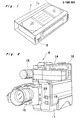
- the present invention generally relates to video tape recorders and more particularly, to a portable integrated video camera/recorder unit in which a video camera for converting an image of an object into video signals and a cassette type video tape recorder for recording onto a magnetic tape of a video tape cassette the video signals delivered from the video camera are integrally combined with each other.
- an erasure prevention tab 2 of a video tape cassette 1 of Fig. 1 is preliminarily snapped off so as to prevent erroneous erasure of the video signals from the magnetic tape or erroneous recording of the video signals onto the magnetic tape.
- an erasure prevention tab 2 of a video tape cassette 1 of Fig. 1 is preliminarily snapped off so as to prevent erroneous erasure of the video signals from the magnetic tape or erroneous recording of the video signals onto the magnetic tape.
- VTR video tape recorder
- the video tape cassette has the erasure prevention tab 2 as shown in Fig. I
- presence of the erasure prevention tab 2 is detected by the detection means such that the video signals can be freely recorded onto or erased from the magnetic tape.
- VTRs it has been generally so arranged that since it is not so necessary to directly convey information regarding presence and absence of the erasure prevention tab to the users, the VTRs do not have a function of displaying whether or not the loaded video tape cassette has the erasure prevention tab 2.
- the information regarding presence and absence of the erasure prevention tab 2 is vital for the operational efficiency. Namely, since the VTRs are required to be operated efficiently, it is desirable that recording of the video signals onto the magnetic tape can be started immediately upon loading of the video tape cassette into the VTRs.
- a recording standby state is established such that recording of the video signals onto the magnetic tape can be started if a decision has been made as to the image of the object to be recorded.
- an essential object of the present invention is to provide a VTR in which when a video tape cassette loaded into the VTR is provided with an erasure prevention tab and is not provided with the erasure prevention tab as in the case of a commercially available prerecorded video tape, the VTR is automatically set to a recording standby state and playback of the VTR can be performed immediately, respectively.
- Another important object of the present invention is to provide a VTR of the above described type in which changeover between a recording mode and a playback mode can be effected rapidly.
- a video tape recorder embodying the present invention comprises: a detection means for detecting presence and absence of an erasure prevention tab of a video tape cassette loaded into said video tape recorder; a display light emitting element; and a control means which is operatively associated with said detection means; said control means, when a first video tape cassette which is provided with said erasure prevention tab has been loaded into said video tape recorder, setting said video tape recorder to a recording standby state and turning on said display light emitting element; said control means, when a second video tape cassette which is not provided with said erasure prevention tab has been loaded into said video tape recorder, setting said video tape recorder to a stop state and flashing said display light emitting element.
- the VTR can be automatically set to the recording standby state or playback of the VTR can be performed immediately on the basis of whether or not the video tape cassette loaded into the VTR is provided with the erasure prevention tab.
- FIG. 2 and 3 an integrated video camera/recorder unit K according to the present invention, in which a video camera section 10 for converting an image of an object into video signals and a video tape recorder (VTR) section 11 for recording onto the magnetic tape of the video tape cassette
- VTR video tape recorder
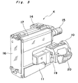
- the unit K further includes a cassette holder 12 for loading the video tape cassette 1 thereinto, an electronic viewfinder 14, a microphone 15, a battery mounting portion 16 for mounting a battery pack thereon, and a pivotal protective cover 17 for covering a mode changeover operating portion.
- a cassette ejection button (not shown) has been depressed after turning on of a power source switch 13 of the unit K, the cassette holder 12 is displaced in parallel with a side face of the VTR section 11 so as to be opened. Meanwhile, when the protective cover 17 has been pivoted so as to uncover the mode changeover operating portion, the mode changeover operating portion is exposed outwardly.
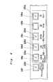
- the mode changeover operating portion includes a Still button (Still Picture Playback button) 18a, a Stop button 18b, a Rewind/Rewind Playback button 18c, a Playback button 18d, a Fast Forward/Fast Forward Playback button 18e and a Record/Playback button 18f.
- the symbol "slash (/)" indicates "or”. Namely, for example, "Rewind/Rewind Playback” means rewinding or rewindin playback. According, when the Rewind/Rewind Playback butto 18c is depressed after depression of the Stop button 18b the magnetic tape of the video tape cassette 1 is rewound. Meanwhile, when the Rewind/Rewind. Playback button 18c i:
- the Record/Playback button 18f is effectively actuated when the video tape cassette 1 having the erasure prevention tab 2 as shown in Fig. 1 has been loaded into the VTR section 11 by inserting the video tape cassette 1 into the cassette holder 12. If the Record/Playback button 18f is depressed when the VTR section 11 is in a recording standby state, the VTR section 11 is changed over to a playback mode so as to be in a still picture playback state. Meanwhile, on the contrary, if the Record/Playback button 18f is depressed when the VTR section 11 is in a playback state, a stop state, a rewinding state or a fast forwarding state, the VTR section 11 is set to the recording standby state.
- the unit K includes a Record Start/Stop button 19 and a grip belt 20 as shown in Fig. 3.
- the Record Start/Stop button 19 is provided adjacent to the grip belt 20 so as to be operated by a thumb of a right hand of the user.
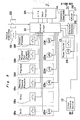
- buttons 18a-18f and 19 are delivered to a control circuit 21 constituted by, for example, a microcomputer.
- the control circuit 21 locates a depressed one of the buttons 18a-18f and 19 and stores its location in the case where the mode of the depressed one of the buttons 18a-18f and 19 is held.
- the VTR section 11 is set to one of the above described modes.
- LEDs 23a, 23c, 23d, 23e and 23f are embedded in central portions of the buttons 18a, 18c, 18d, 18e and 18f, respectively. Signals for turning on the LEDs 23a and 23c-23f are also outputted from the control circuit 21.
- the control circuit 21 controls a deck portion 24 of the VTR section 11 so as to set the VTR section 11 to a desired one of the modes.
- the cassette holder 12 is opened and then, the video tape cassette 1 is inserted into the cassette holder 12.
- the detection switch 22 detects kinds of the video tape cassette 1, i.e., presence and absence of the erasure prevention tab 2 of the video tape cassette 1.
- an actuator of the detection switch 22 is brought into contact with the erasure prevention tab 2 and thus, the detection switch 22 is turned on.
- the actuator of the detection switch 22 is inserted into a hole of the video tape cassette 1, which is defined by removal of the erasure prevention tab 2 therefrom and thus, the detection switch 22 is turned off. Accordingly, "on” and “off” signals of the detection switch 22 act as decision signals for determining presence and absence of the erasure prevention tab 2 of the video tape cassette 1, respectively. Since one of the decision signals of the detection switch 22 has been applied to the control circuit 21, the VTR section 11 is set to one of the modes by the decision signals and signals obtained upon operation of the buttons 18a-18f and 19. In addition, output signals are delivered from the control circuit 21 to the LEDs 23a and 23c-23f so as to operate the deck portion 24 of the VTR section 11.
- the VTR section 11 is immediately set to the recording standby state and the LED 23f for indicating recording is turned on.
- the Record Start/Stop button 19 is depressed and thus, the magnetic tape is caused to run such that an image of an object taken by the video camera section 10 is recorded, as video signals, onto the magnetic tape.
- the Record Start/Stop button 19 is depressed again, so that the VTR section 11 is set to the temporary stop state. Thereafter, in order to resume recording, the Record Start/Stop button 19 is depressed.
- the VTR section 11 is set to the temporary stop state (standby state) and then, the Record/Playback button 18f is depressed.
- the VTR section 11 is set to the still playback state, while the LED 23a for indicating display of a still picture and the LED 23d for indicating playback are turned on.
- the Rewind/Rewind Playback Button 18c is depressed when the VTR section 11 is in the playback state, so that the VTR section 11 is set to the rewinding playback state and thus, the recorded portion of the magnetic tape is played back while the magnetic tape is being rewound.
- the VTR section 11 is set to the rewinding state. Then, when the VTR section 11 is set to the playback state after the magnetic tape has been rewound up to a desired position by viewing a tape counter, etc., it becomes also possible to play back the recorded portion of the magnetic tape.
- the VTR section 11 is actuated as follows. Namely, since information that the video tape cassette 1 is not provided with the erasure prevention tab 2 is obtained by the detection switch 22 as described above, the VTR section 11 judges that it is not necessary to perform recording any more. Therefore, since the VTR section 11 is not set to the recording standby state, the VTR section 11 informs initially the user that the video tape cassette 1 loaded into the VTR section 11 is a commercially available prerecorded video tape cassette or a video tape cassette disabling recording regardless of whether or not the user is aware of this fact.
- the LED 23f for indicating recording is flashed by repeatedly turning on and off the LED 23f for 0.5 sec., respectively alternately.
- the integrated video camera/recorder unit K is provided with the electronic viewfinder 14 for monitoring an image of an object being taken by the video camera section 10.
- warning characters generated by a character generator 26, for example, "TAPE" are displayed on a screen of the electronic viewfinder 14, the user becomes aware immediately that the video tape cassette 1 loaded into the VTR section 11 is a commercially available prerecorded video tape cassette or a recorded video tape cassette, which is fairly convenient for the user. Accordingly, buttons which can be operated subsequently by the user are restricted to the buttons 18a, 18b and 18c.
- buttons 18f and 19 are not actuated. It is needless to say that in the case where one of the video tape cassettes 1 which is provided with and is not provided with the erasure prevention tab 2, respectively has been loaded into the VTR section 11 when the power source switch 13 is not turned on, the VTR section 11 is set to the above described modes after turning on of the power source switch 13. Meanwhile, in Fig. 5, reference numerals 27 and 28 represent a mixer and an output terminal, respectively.
- the VTR of the present invention when the video tape cassette provided with the erasure prevention tab has been loaded into the VTR, the VTR is automatically set to the recording standby state and the light emitting element for indicating recording is turned on. Meanwhile, when the video tape cassette which is not provided with the erasure prevention tab has been loaded into the VTR, the VTR is not set to the recording standby state and the light emitting element for indicating recording is flashed.
- the VTR can be operated remarkably efficiently and easily.
Landscapes
- Engineering & Computer Science (AREA)
- Multimedia (AREA)
- Signal Processing (AREA)
- Management Or Editing Of Information On Record Carriers (AREA)
Applications Claiming Priority (2)
| Application Number | Priority Date | Filing Date | Title |
|---|---|---|---|
| JP277150/84 | 1984-12-24 | ||
| JP59277150A JPH0624072B2 (ja) | 1984-12-24 | 1984-12-24 | カメラ一体型ビデオテ−プレコ−ダ |
Publications (3)
| Publication Number | Publication Date |
|---|---|
| EP0186901A2 true EP0186901A2 (de) | 1986-07-09 |
| EP0186901A3 EP0186901A3 (en) | 1987-10-07 |
| EP0186901B1 EP0186901B1 (de) | 1991-03-06 |
Family
ID=17579494
Family Applications (1)
| Application Number | Title | Priority Date | Filing Date |
|---|---|---|---|
| EP85116535A Expired - Lifetime EP0186901B1 (de) | 1984-12-24 | 1985-12-23 | Videobandaufnahmegerät |
Country Status (5)
| Country | Link |
|---|---|
| US (1) | US4731677A (de) |
| EP (1) | EP0186901B1 (de) |
| JP (1) | JPH0624072B2 (de) |
| KR (1) | KR900001260B1 (de) |
| DE (1) | DE3582041D1 (de) |
Cited By (3)
| Publication number | Priority date | Publication date | Assignee | Title |
|---|---|---|---|---|
| DE3727327A1 (de) * | 1986-08-22 | 1988-02-25 | Samsung Electronics Co Ltd | Leistungszufuhr- und eingangssignalschaltsteuerung fuer einen videorekorder |
| EP0259589A3 (en) * | 1986-09-08 | 1989-11-02 | Company Hewlett-Packard | Automatic loading hub for supply reel on reel to teel tape drive and method |
| EP0766241A1 (de) * | 1991-11-28 | 1997-04-02 | Sony Corporation | Videosignalwiedergabegerät |
Families Citing this family (9)
| Publication number | Priority date | Publication date | Assignee | Title |
|---|---|---|---|---|
| US4910604A (en) * | 1986-05-21 | 1990-03-20 | Canon Kabushiki Kaisha | Image transmission apparatus |
| KR910006609B1 (ko) * | 1986-12-18 | 1991-08-29 | 가시오 게이상기 가부시기가이샤 | 전자 스틸 카메라 |
| JPH01126659U (de) * | 1988-02-10 | 1989-08-30 | ||
| JPH0722356B2 (ja) * | 1988-06-11 | 1995-03-08 | 富士写真フイルム株式会社 | カメラ一体型vtrおよびビデオカメラ |
| KR100189867B1 (ko) * | 1991-01-30 | 1999-06-01 | 윤종용 | 비데오 카메라의 모우드 선택방법 |
| JP4944306B2 (ja) | 2001-04-16 | 2012-05-30 | キヤノン株式会社 | 記録装置 |
| JP3748257B2 (ja) * | 2003-01-31 | 2006-02-22 | 船井電機株式会社 | Ieee1394シリアルバスに接続されるコントローラ機器とそれを用いたネットワークシステム |
| JP2005182849A (ja) * | 2003-12-15 | 2005-07-07 | Canon Inc | 記録再生装置 |
| EP2213089B1 (de) * | 2007-10-26 | 2012-08-29 | Cisco Technology, Inc. | Daten-konnektor für ein elektronikgerät |
Family Cites Families (11)
| Publication number | Priority date | Publication date | Assignee | Title |
|---|---|---|---|---|
| US3588375A (en) * | 1970-01-14 | 1971-06-28 | Leach Corp | Multichannel tape recorder with double recording prevention means |
| JPS4736320U (de) * | 1971-05-14 | 1972-12-22 | ||
| BE803637A (fr) * | 1973-08-14 | 1973-12-03 | Staar Sa | Dispositif permettant d'empecher l'effacement d'une bande magnetique dans les appareils permettant un enregistrement et/ou une reproduction dans les deux sens de defilement de la bande |
| JPS6141193Y2 (de) * | 1977-03-16 | 1986-11-22 | ||
| JPS53144320U (de) * | 1977-04-20 | 1978-11-14 | ||
| JPS54140515A (en) * | 1978-04-23 | 1979-10-31 | Canon Inc | Video recorder |
| US4340095A (en) * | 1979-09-17 | 1982-07-20 | Dale John D | Material transferring apparatus |
| JPS57150282A (en) * | 1981-03-12 | 1982-09-17 | Hitachi Ltd | Magnetic picture recording and reproducing device |
| JPS5850869A (ja) * | 1981-09-21 | 1983-03-25 | Canon Inc | スチルビデオカメラ |
| JPS58203653A (ja) * | 1982-05-20 | 1983-11-28 | Canon Inc | 誤消去防止のための表示装置 |
| US4541010A (en) * | 1983-06-17 | 1985-09-10 | Polaroid Corporation | Electronic imaging camera |
-
1984
- 1984-12-24 JP JP59277150A patent/JPH0624072B2/ja not_active Expired - Lifetime
-
1985
- 1985-11-21 KR KR1019850008695A patent/KR900001260B1/ko not_active Expired
- 1985-12-18 US US06/810,695 patent/US4731677A/en not_active Expired - Lifetime
- 1985-12-23 DE DE8585116535T patent/DE3582041D1/de not_active Expired - Lifetime
- 1985-12-23 EP EP85116535A patent/EP0186901B1/de not_active Expired - Lifetime
Cited By (4)
| Publication number | Priority date | Publication date | Assignee | Title |
|---|---|---|---|---|
| DE3727327A1 (de) * | 1986-08-22 | 1988-02-25 | Samsung Electronics Co Ltd | Leistungszufuhr- und eingangssignalschaltsteuerung fuer einen videorekorder |
| EP0259589A3 (en) * | 1986-09-08 | 1989-11-02 | Company Hewlett-Packard | Automatic loading hub for supply reel on reel to teel tape drive and method |
| EP0766241A1 (de) * | 1991-11-28 | 1997-04-02 | Sony Corporation | Videosignalwiedergabegerät |
| US5832173A (en) * | 1991-11-28 | 1998-11-03 | Sony Corporation | Apparatus for reproducing a video signal recorded on tape and for searching the tape |
Also Published As
| Publication number | Publication date |
|---|---|
| US4731677A (en) | 1988-03-15 |
| DE3582041D1 (de) | 1991-04-11 |
| JPH0624072B2 (ja) | 1994-03-30 |
| EP0186901B1 (de) | 1991-03-06 |
| EP0186901A3 (en) | 1987-10-07 |
| KR900001260B1 (ko) | 1990-03-05 |
| KR860005360A (ko) | 1986-07-21 |
| JPS61150149A (ja) | 1986-07-08 |
Similar Documents
| Publication | Publication Date | Title |
|---|---|---|
| US4731677A (en) | Integrated video camera/recorder unit | |
| US7062576B2 (en) | Digital camera having imaging portion, first terminal, and second terminal for outputting signals based on image data in accordance with same data communication interface standard | |
| JP2899023B2 (ja) | ビデオシステム | |
| US6564002B1 (en) | Editing system and method, image recorder, editing device and recording medium | |
| KR910004322B1 (ko) | 재생 기능을 구비한 vtr 일체형 카메라 및 그 조작방법 | |
| US7489413B2 (en) | Apparatus having means for printing video signals of video camera attached thereto | |
| CA1278375C (en) | Cassette type recording apparatus | |
| US4727443A (en) | Method of protecting a magnetic recording medium in a magnetic recording/playback system and apparatus therefor | |
| US4417135A (en) | Power saving electronic counter circuit for tape recorder | |
| US5995319A (en) | Electronic apparatus having a main body and a detachable input /or output block | |
| US4701813A (en) | Method of protecting a magnetic recording medium in a magnetic recording/playback system and apparatus therefor | |
| JPWO2001015068A1 (ja) | 記録及び/又は再生装置及び記憶媒体のローディング方法 | |
| JPH05347727A (ja) | 撮像機器 | |
| JPS5841472A (ja) | カセツト | |
| JP2900376B2 (ja) | 静止画像記録再生装置 | |
| US5258875A (en) | Video tape recorder with the function of repetitive playback | |
| US6650829B2 (en) | Signal recording apparatus and method | |
| KR920003990B1 (ko) | 자기기록재생장치 | |
| JPS6341670Y2 (de) | ||
| JP2555017Y2 (ja) | テープレコーダ | |
| JP2902650B2 (ja) | 画像再生処理装置 | |
| JPH0542749B2 (de) | ||
| JPH0352157B2 (de) | ||
| JPH0548258Y2 (de) | ||
| KR200162989Y1 (ko) | 드럼의 이슬감지 기능을 갖는 브이시알 시스템 |
Legal Events
| Date | Code | Title | Description |
|---|---|---|---|
| PUAI | Public reference made under article 153(3) epc to a published international application that has entered the european phase |
Free format text: ORIGINAL CODE: 0009012 |
|
| AK | Designated contracting states |
Kind code of ref document: A2 Designated state(s): DE GB |
|
| PUAL | Search report despatched |
Free format text: ORIGINAL CODE: 0009013 |
|
| AK | Designated contracting states |
Kind code of ref document: A3 Designated state(s): DE GB |
|
| 17P | Request for examination filed |
Effective date: 19871117 |
|
| 17Q | First examination report despatched |
Effective date: 19900523 |
|
| GRAA | (expected) grant |
Free format text: ORIGINAL CODE: 0009210 |
|
| AK | Designated contracting states |
Kind code of ref document: B1 Designated state(s): DE GB |
|
| REF | Corresponds to: |
Ref document number: 3582041 Country of ref document: DE Date of ref document: 19910411 |
|
| PLBE | No opposition filed within time limit |
Free format text: ORIGINAL CODE: 0009261 |
|
| STAA | Information on the status of an ep patent application or granted ep patent |
Free format text: STATUS: NO OPPOSITION FILED WITHIN TIME LIMIT |
|
| 26N | No opposition filed | ||
| REG | Reference to a national code |
Ref country code: GB Ref legal event code: IF02 |
|
| PGFP | Annual fee paid to national office [announced via postgrant information from national office to epo] |
Ref country code: DE Payment date: 20041216 Year of fee payment: 20 |
|
| PGFP | Annual fee paid to national office [announced via postgrant information from national office to epo] |
Ref country code: GB Payment date: 20041222 Year of fee payment: 20 |
|
| PG25 | Lapsed in a contracting state [announced via postgrant information from national office to epo] |
Ref country code: GB Free format text: LAPSE BECAUSE OF EXPIRATION OF PROTECTION Effective date: 20051222 |
|
| REG | Reference to a national code |
Ref country code: GB Ref legal event code: PE20 |