EP0186546A1 - Elektrischer Schalter mit Schirm - Google Patents
Elektrischer Schalter mit Schirm Download PDFInfo
- Publication number
- EP0186546A1 EP0186546A1 EP85402285A EP85402285A EP0186546A1 EP 0186546 A1 EP0186546 A1 EP 0186546A1 EP 85402285 A EP85402285 A EP 85402285A EP 85402285 A EP85402285 A EP 85402285A EP 0186546 A1 EP0186546 A1 EP 0186546A1
- Authority
- EP
- European Patent Office
- Prior art keywords
- screen
- contacts
- switch
- flap
- cavity
- Prior art date
- Legal status (The legal status is an assumption and is not a legal conclusion. Google has not performed a legal analysis and makes no representation as to the accuracy of the status listed.)
- Granted
Links
- 239000007789 gas Substances 0.000 claims description 6
- 238000000926 separation method Methods 0.000 claims description 4
- 230000008878 coupling Effects 0.000 claims description 2
- 238000010168 coupling process Methods 0.000 claims description 2
- 238000005859 coupling reaction Methods 0.000 claims description 2
- 238000007789 sealing Methods 0.000 abstract description 3
- 238000006073 displacement reaction Methods 0.000 description 4
- 238000002955 isolation Methods 0.000 description 2
- 238000006677 Appel reaction Methods 0.000 description 1
- 230000000295 complement effect Effects 0.000 description 1
- 230000006837 decompression Effects 0.000 description 1
- 230000000694 effects Effects 0.000 description 1
- 238000010891 electric arc Methods 0.000 description 1
- 238000010926 purge Methods 0.000 description 1
- 238000010008 shearing Methods 0.000 description 1
- 230000001052 transient effect Effects 0.000 description 1
- 238000004804 winding Methods 0.000 description 1
Images
Classifications
-
- H—ELECTRICITY
- H01—ELECTRIC ELEMENTS
- H01H—ELECTRIC SWITCHES; RELAYS; SELECTORS; EMERGENCY PROTECTIVE DEVICES
- H01H9/00—Details of switching devices, not covered by groups H01H1/00 - H01H7/00
- H01H9/30—Means for extinguishing or preventing arc between current-carrying parts
- H01H9/32—Insulating body insertable between contacts
Definitions
- the invention relates to an electrical screen switch comprising in a housing two contacts movable relative to each other, means for controlling the opening of this switch, a movable screen and propulsion means which rapidly move a edge of this screen between the contacts so as to shear, between this edge and an insulating wall contained in the housing, the arc appearing between these contacts at the time of their separation.
- breaking devices capable of interrupting in a line where they are placed in series, either transient currents, for example, consecutive to the appearance of short circuits, or permanent currents whose nominal intensity is high.
- Such switches are already known, for example from French patent application No. 83 01749 of February 4, 1983 from the Applicant. If the means which are used to cause the displacement of the screen do not respond to the growth speed or to the threshold of the intensity of the current to be interrupted, there is a risk of not obtaining the same quality of cut-off in each of the situations where such an interruption is necessary.
- the object of the invention is therefore to provide such known switches with means which will be capable of adapting the speed of movement of the screen to the energy which is released by the arc at when it is established between contacts.
- the aim is achieved thanks to the fact that the screen provided with an opening through which one of the contacts of the switch passes, and a movable insulating flap to which it is connected, move at the same time in a body cavity so as to contain between them and surfaces of this cavity, a space of variable volume which contains one of the contacts which increases rapidly in volume when the heat of the arc appearing at the opening is communicated to the gases contained in this volume, and which is connected to the atmosphere for a particular position of this screen where the opening is no longer opposite the contact.
- the gas pressure developed at the moment when the arc appears is applied to a movable insulating drive flap which is connected to a movable screen and which forms at that time, with walls of the housing, a substantially sealed volume or space.
- variable volume is not comprised between walls belonging to a case having a hollow or tubular configuration
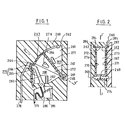
- an insulating flat screen 219 having an opening 220 can slide along a surface 221 belonging to a cavity 222 of an insulating housing 223; side edges 224, 225, see FIG. 4, as well as a rear portion 226 of the screen are engaged with a functional clearance in grooves 227, 228, 229 of the cavity to ensure, when the screen is moved towards the at the top of figure 3, an electrical isolation total stick between the cavity, where is placed a movable contact lever 230 whose contact pad 232 passes through the opening, and a fixed contact 231 which is set back from the surface 221.
- An end region 233 of the screen, directed towards the cavity has coupling means 234 able to cooperate with one end 235 of a flap 236 which pivots at the other end around an axis 237.
- This end this pivot point, as well as the lateral edges 247, 248 of the flap, cooperate with the walls of the cavity and, respectively, with the screen in a sufficiently tight manner so that an electric arc, appearing between the contacts at moment of their separation, produces, in the variable volume 238 of the cavity where the movable contact is located, a sufficiently rapid rise in pressure so that the screen is very quickly driven by the shutter towards the top of the figure and performs a shearing of this arc between the opening 220 and an edge 239 of the surface 221.
- a vent 240 passing through the housing to the cavity allows the variable volume to be purged for a certain position of the flap.
- Terminals 241, 242 and a flexible braid 243 make it possible to connect the switch 244 to a use circuit.
- an overcurrent for example, a magnetizable U-shaped part
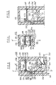
- the screen 250 and the flap 251 could be molded in a single insulating piece 256, the variable volume 252 being contained here between rigid screen walls 253 and 254, 254 ′, 254 "from the housing, and a deformable wall of the shutter 255 being embedded at one end in the housing to form an apparent pivot axis 257.
- an insulating housing body 260 comprises a cavity 261 having a cylindrical surface 262 opposite which angularly displaces with a very small clearance a screen of the same curvature 263 which is provided with an opening 264 to let pass, in its rest position, a movable contact 265 cooperating with the fixed contact 266 placed opposite.
- This rigid screen is integral with a radial flap 267 which is articulated on a transverse pivot 268 placed at the center of curvature of the surface 262 and which has, with the other walls 269, 270, 271 of the cavity 261, by means of cheeks 272 , 273 and to a hub 274, see FIG. 2, a sufficiently good seal so that the gases, the pressure of which rises in the space of variable volume 288 at the appearance of an arc resulting from the opening of the 'switch 275, drive the shutter clockwise; here again, decompression openings such as 276 in a cheek of the flap come opposite a vent 277 of the housing cavity for a particular position of the screen.
- terminals 278, 279, a braid 280, a pressure spring 281 and automatic opening means such as 282 are associated with the contact lever 283; moreover, the sealing of the screen is improved by virtue of tangential edges 284, 285 which circulate in grooves 286, 287 of the housing.
- the initial movement of the movable contact levers which slightly precedes the movement of the shutter and of the screen, so as to reveal the arc whose energy is exploited, is supposed to be caused by a magnetizable structure 246, respectively 282, whose effectiveness is real when the intensities of the currents flowing in the lever are very high and that other magnetic means of displacement are then subject to saturation.
- windings placed in series and associated with cores, or rapid movable pallets can be used so that the movements of these parts communicate initial openings to the various movable contacts.
Landscapes
- Arc-Extinguishing Devices That Are Switches (AREA)
- Circuit Breakers (AREA)
- Push-Button Switches (AREA)
- Electrical Discharge Machining, Electrochemical Machining, And Combined Machining (AREA)
- Breakers (AREA)
- Driving Mechanisms And Operating Circuits Of Arc-Extinguishing High-Tension Switches (AREA)
- Input Circuits Of Receivers And Coupling Of Receivers And Audio Equipment (AREA)
- Cookers (AREA)
- Switches That Are Operated By Magnetic Or Electric Fields (AREA)
- Automatic Disk Changers (AREA)
- Electronic Switches (AREA)
- Electrophonic Musical Instruments (AREA)
- Glass Compositions (AREA)
- Distribution Board (AREA)
- Switch Cases, Indication, And Locking (AREA)
- Oscillators With Electromechanical Resonators (AREA)
- Switches With Compound Operations (AREA)
- Saccharide Compounds (AREA)
Priority Applications (1)
| Application Number | Priority Date | Filing Date | Title |
|---|---|---|---|
| AT85402285T ATE40491T1 (de) | 1984-11-26 | 1985-11-25 | Elektrischer schalter mit schirm. |
Applications Claiming Priority (2)
| Application Number | Priority Date | Filing Date | Title |
|---|---|---|---|
| FR8417964 | 1984-11-26 | ||
| FR8417964A FR2573914B1 (fr) | 1984-11-26 | 1984-11-26 | Interrupteur electrique a ecran |
Publications (2)
| Publication Number | Publication Date |
|---|---|
| EP0186546A1 true EP0186546A1 (de) | 1986-07-02 |
| EP0186546B1 EP0186546B1 (de) | 1989-01-25 |
Family
ID=9309926
Family Applications (1)
| Application Number | Title | Priority Date | Filing Date |
|---|---|---|---|
| EP85402285A Expired EP0186546B1 (de) | 1984-11-26 | 1985-11-25 | Elektrischer Schalter mit Schirm |
Country Status (14)
| Country | Link |
|---|---|
| US (1) | US4659887A (de) |
| EP (1) | EP0186546B1 (de) |
| JP (1) | JPS61153909A (de) |
| AT (1) | ATE40491T1 (de) |
| BR (1) | BR8505921A (de) |
| CA (1) | CA1250009A (de) |
| CH (1) | CH664847A5 (de) |
| DE (1) | DE3541745C2 (de) |
| ES (1) | ES8609806A1 (de) |
| FR (1) | FR2573914B1 (de) |
| GB (1) | GB2167903B (de) |
| IE (1) | IE56994B1 (de) |
| IT (1) | IT1186215B (de) |
| ZA (1) | ZA859037B (de) |
Cited By (1)
| Publication number | Priority date | Publication date | Assignee | Title |
|---|---|---|---|---|
| EP0244276B1 (de) * | 1986-04-04 | 1991-06-05 | Telemecanique | Elektrischer Schalter für Schutzgerät, wie Schutzschalter |
Families Citing this family (13)
| Publication number | Priority date | Publication date | Assignee | Title |
|---|---|---|---|---|
| FR2596196B1 (fr) * | 1986-03-21 | 1988-08-26 | Telemecanique Electrique | Appareil interrupteur de protection muni d'un ecran de coupure d'arc |
| DE3723538A1 (de) * | 1987-07-16 | 1989-01-26 | Sachsenwerk Ag | Loeschkammer zur unterbrechung von laststromkreisen |
| DE3823790A1 (de) * | 1988-07-14 | 1990-01-18 | Asea Brown Boveri | Elektrisches installationsgeraet mit kontakttrennwand |
| CH677986A5 (de) * | 1988-07-27 | 1991-07-15 | Sprecher & Schuh Ag | |
| US4926610A (en) * | 1988-12-12 | 1990-05-22 | The Standard Products Company | Variable-width molding and brightwork |
| US5780800A (en) * | 1996-08-07 | 1998-07-14 | General Electric Company | Circuit breaker contact arm and spring shield |
| DE19726402B4 (de) * | 1997-06-21 | 2009-03-05 | Marquardt Gmbh | Elektrischer Schalter |
| DE10001632A1 (de) | 2000-01-17 | 2001-08-02 | Harting Automotive Gmbh & Co | Leitungsunterbrecher |
| DE102006033766A1 (de) * | 2006-01-25 | 2007-07-26 | Abb Technology Ag | Kontaktanordnung für eine Kurzschließeinrichtung in einer Mittel- oder Hochspannungsschaltanlage |
| DE102017207426A1 (de) * | 2017-05-03 | 2018-11-08 | Siemens Aktiengesellschaft | Mechanisches Schaltgerät zur Stromunterbrechung |
| CN108987139B (zh) * | 2017-06-01 | 2024-02-02 | 泰科电子(深圳)有限公司 | 电触头系统 |
| EP3561831B1 (de) * | 2018-04-24 | 2022-10-26 | ABB Schweiz AG | Elektrischer schalter |
| US11948762B2 (en) * | 2021-04-30 | 2024-04-02 | Astronics Advanced Electronic Systems Corp. | High voltage high current arc extinguishing contactor |
Citations (2)
| Publication number | Priority date | Publication date | Assignee | Title |
|---|---|---|---|---|
| DE472305C (de) * | 1927-10-30 | 1929-02-26 | Siemens Schuckertwerke Akt Ges | Loeschkammer fuer Schalter |
| EP0118333A1 (de) * | 1983-02-04 | 1984-09-12 | Telemecanique | Schalter mit einer sich beim Ausschalten zwischen den Kontakten einschiebenden Isolierstoffwand und mit Lichtbogenabquetschmittel zwischen der Isolierstoffwand und einem Isolierstoffgehäuse |
Family Cites Families (4)
| Publication number | Priority date | Publication date | Assignee | Title |
|---|---|---|---|---|
| DE2829860A1 (de) * | 1978-07-07 | 1980-01-17 | Hartmann & Braun Ag | Elektrischer schalter mit einander gegenueberliegenden schaltkontakten |
| CA1133504A (en) * | 1978-11-24 | 1982-10-12 | Robert J. Knopf | Carboxylated polyalkylene oxides |
| US4426562A (en) * | 1981-10-06 | 1984-01-17 | Westinghouse Electric Corp. | Rotary switch for switching very large DC currents |
| US4510360A (en) * | 1983-06-08 | 1985-04-09 | Westinghouse Electric Corp. | Circuit breaker with arc shield |
-
1984
- 1984-11-26 FR FR8417964A patent/FR2573914B1/fr not_active Expired
-
1985
- 1985-11-25 CA CA000496136A patent/CA1250009A/fr not_active Expired
- 1985-11-25 IT IT22976/85A patent/IT1186215B/it active
- 1985-11-25 CH CH5012/85A patent/CH664847A5/fr not_active IP Right Cessation
- 1985-11-25 AT AT85402285T patent/ATE40491T1/de active
- 1985-11-25 US US06/802,094 patent/US4659887A/en not_active Expired - Fee Related
- 1985-11-25 EP EP85402285A patent/EP0186546B1/de not_active Expired
- 1985-11-26 IE IE2969/85A patent/IE56994B1/xx unknown
- 1985-11-26 JP JP60265974A patent/JPS61153909A/ja active Pending
- 1985-11-26 GB GB8529130A patent/GB2167903B/en not_active Expired
- 1985-11-26 BR BR8505921A patent/BR8505921A/pt not_active IP Right Cessation
- 1985-11-26 ES ES549292A patent/ES8609806A1/es not_active Expired
- 1985-11-26 DE DE3541745A patent/DE3541745C2/de not_active Expired - Fee Related
- 1985-11-26 ZA ZA859037A patent/ZA859037B/xx unknown
Patent Citations (2)
| Publication number | Priority date | Publication date | Assignee | Title |
|---|---|---|---|---|
| DE472305C (de) * | 1927-10-30 | 1929-02-26 | Siemens Schuckertwerke Akt Ges | Loeschkammer fuer Schalter |
| EP0118333A1 (de) * | 1983-02-04 | 1984-09-12 | Telemecanique | Schalter mit einer sich beim Ausschalten zwischen den Kontakten einschiebenden Isolierstoffwand und mit Lichtbogenabquetschmittel zwischen der Isolierstoffwand und einem Isolierstoffgehäuse |
Cited By (1)
| Publication number | Priority date | Publication date | Assignee | Title |
|---|---|---|---|---|
| EP0244276B1 (de) * | 1986-04-04 | 1991-06-05 | Telemecanique | Elektrischer Schalter für Schutzgerät, wie Schutzschalter |
Also Published As
| Publication number | Publication date |
|---|---|
| DE3541745A1 (de) | 1986-05-28 |
| ATE40491T1 (de) | 1989-02-15 |
| DE3541745C2 (de) | 1995-06-08 |
| GB8529130D0 (en) | 1986-01-02 |
| GB2167903B (en) | 1989-06-07 |
| US4659887A (en) | 1987-04-21 |
| IT8522976A0 (it) | 1985-11-25 |
| ZA859037B (en) | 1986-08-27 |
| GB2167903A (en) | 1986-06-04 |
| ES8609806A1 (es) | 1986-07-16 |
| BR8505921A (pt) | 1986-08-19 |
| IE852969L (en) | 1986-05-26 |
| FR2573914B1 (fr) | 1987-02-06 |
| IE56994B1 (en) | 1992-02-26 |
| FR2573914A1 (fr) | 1986-05-30 |
| IT1186215B (it) | 1987-11-18 |
| CH664847A5 (fr) | 1988-03-31 |
| EP0186546B1 (de) | 1989-01-25 |
| ES549292A0 (es) | 1986-07-16 |
| JPS61153909A (ja) | 1986-07-12 |
| CA1250009A (fr) | 1989-02-14 |
Similar Documents
| Publication | Publication Date | Title |
|---|---|---|
| EP0186546B1 (de) | Elektrischer Schalter mit Schirm | |
| FR2677168A1 (fr) | Disjoncteur moyenne tension a energie de commande reduite. | |
| FR2714520A1 (fr) | Appareil électrique interrupteur à contacts séparables. | |
| EP0239068A1 (de) | Druckgasschalter | |
| EP0179834B1 (de) | Schaltvorrichtung mit trennwand zum unterbrechen des lichtbogens | |
| CH651421A5 (fr) | Disjoncteur a auto-soufflage pneumatique. | |
| EP0306382B1 (de) | Schalteranordnung für elektrische mehrpolige Schutzschalter mit mehreren Kontakten | |
| FR2720188A1 (fr) | Disjoncteur à autocompression réduite. | |
| EP1764811B1 (de) | Trennschalter mit einer verkleineten Lichtbogenlöschkammer | |
| EP0302390A1 (de) | Druckgasschalter für Hoch- oder Mittelspannung mit von der Lichtbogenenergie entnommener Ausschaltenergie | |
| WO2002049053A1 (fr) | Appareil de coupure electronique pour installation electrique | |
| EP0693763A1 (de) | Mittelspannung elektrischer Schalter | |
| EP0704872B1 (de) | Mittelspannungsschalter oder Schutzschalter | |
| EP1665316B1 (de) | Abschalteinrichtung für elektrischen strom mit vollständiger unterscheidung von zuständen | |
| FR2766609A1 (fr) | Interrupteur a gaz a volume d'expansion thermique compressible | |
| EP0458236B1 (de) | Mittelspannungsschalter | |
| EP1515352B1 (de) | Vorrichtung zur elektrischen Stromabschaltung mit einem translatorisch bewegbaren Kontakt | |
| FR2665030A1 (fr) | Dispositif de commutation recevant un certain nombre de commutateurs dans un boitier. | |
| CA1182153A (fr) | Dispositif de liberation des contacts mobiles de contacteurs aptes a limiter les courants de courts-circuits | |
| FR2589618A1 (fr) | Dispositif de protection pour condensateur en boitier etanche | |
| FR2845516A1 (fr) | Appareil electromagnetique de coupure a dispositif d'actionnement manuel | |
| EP0078719A1 (de) | Selbstblasschalter mit Dauermagnet | |
| FR2857779A1 (fr) | Disjoncteur multipolaire | |
| EP0794547A1 (de) | Elektrischer Schutzschalter mit elektromagnetischen Betätiger und Betätigungsmechanismus | |
| FR2705494A1 (fr) | Disjoncteur à manÓoeuvre assistée par voie électrodynamique. |
Legal Events
| Date | Code | Title | Description |
|---|---|---|---|
| PUAI | Public reference made under article 153(3) epc to a published international application that has entered the european phase |
Free format text: ORIGINAL CODE: 0009012 |
|
| 17P | Request for examination filed |
Effective date: 19851128 |
|
| AK | Designated contracting states |
Kind code of ref document: A1 Designated state(s): AT BE LU NL SE |
|
| 17Q | First examination report despatched |
Effective date: 19880524 |
|
| GRAA | (expected) grant |
Free format text: ORIGINAL CODE: 0009210 |
|
| AK | Designated contracting states |
Kind code of ref document: B1 Designated state(s): AT BE LU NL SE |
|
| REF | Corresponds to: |
Ref document number: 40491 Country of ref document: AT Date of ref document: 19890215 Kind code of ref document: T |
|
| PLBE | No opposition filed within time limit |
Free format text: ORIGINAL CODE: 0009261 |
|
| STAA | Information on the status of an ep patent application or granted ep patent |
Free format text: STATUS: NO OPPOSITION FILED WITHIN TIME LIMIT |
|
| 26N | No opposition filed | ||
| PGFP | Annual fee paid to national office [announced via postgrant information from national office to epo] |
Ref country code: AT Payment date: 19911018 Year of fee payment: 7 |
|
| PGFP | Annual fee paid to national office [announced via postgrant information from national office to epo] |
Ref country code: LU Payment date: 19911118 Year of fee payment: 7 |
|
| PGFP | Annual fee paid to national office [announced via postgrant information from national office to epo] |
Ref country code: SE Payment date: 19911125 Year of fee payment: 7 |
|
| PGFP | Annual fee paid to national office [announced via postgrant information from national office to epo] |
Ref country code: NL Payment date: 19911130 Year of fee payment: 7 |
|
| PGFP | Annual fee paid to national office [announced via postgrant information from national office to epo] |
Ref country code: BE Payment date: 19911217 Year of fee payment: 7 |
|
| EPTA | Lu: last paid annual fee | ||
| PG25 | Lapsed in a contracting state [announced via postgrant information from national office to epo] |
Ref country code: LU Free format text: LAPSE BECAUSE OF NON-PAYMENT OF DUE FEES Effective date: 19921125 Ref country code: AT Effective date: 19921125 |
|
| PG25 | Lapsed in a contracting state [announced via postgrant information from national office to epo] |
Ref country code: SE Effective date: 19921126 |
|
| PG25 | Lapsed in a contracting state [announced via postgrant information from national office to epo] |
Ref country code: BE Effective date: 19921130 |
|
| BERE | Be: lapsed |
Owner name: LA TELEMECANIQUE ELECTRIQUE Effective date: 19921130 |
|
| PG25 | Lapsed in a contracting state [announced via postgrant information from national office to epo] |
Ref country code: NL Effective date: 19930601 |
|
| NLV4 | Nl: lapsed or anulled due to non-payment of the annual fee | ||
| EUG | Se: european patent has lapsed |
Ref document number: 85402285.2 Effective date: 19930610 |