EP0185696B1 - Prüfen von flüssigen schmelzen und dazu geeignete sonden - Google Patents
Prüfen von flüssigen schmelzen und dazu geeignete sonden Download PDFInfo
- Publication number
- EP0185696B1 EP0185696B1 EP85902585A EP85902585A EP0185696B1 EP 0185696 B1 EP0185696 B1 EP 0185696B1 EP 85902585 A EP85902585 A EP 85902585A EP 85902585 A EP85902585 A EP 85902585A EP 0185696 B1 EP0185696 B1 EP 0185696B1
- Authority
- EP
- European Patent Office
- Prior art keywords
- rod
- probe
- melt
- ultrasound
- cooling
- Prior art date
- Legal status (The legal status is an assumption and is not a legal conclusion. Google has not performed a legal analysis and makes no representation as to the accuracy of the status listed.)
- Expired - Lifetime
Links
- 239000000523 sample Substances 0.000 title claims abstract description 89
- 239000000155 melt Substances 0.000 title claims abstract description 66
- 238000012360 testing method Methods 0.000 title claims abstract description 16
- 239000007788 liquid Substances 0.000 title abstract description 15
- 238000002604 ultrasonography Methods 0.000 claims abstract description 37
- 238000001816 cooling Methods 0.000 claims abstract description 36
- 229910052751 metal Inorganic materials 0.000 claims abstract description 29
- 239000002184 metal Substances 0.000 claims abstract description 28
- 238000000034 method Methods 0.000 claims abstract description 14
- 239000013078 crystal Substances 0.000 claims abstract description 13
- 239000010959 steel Substances 0.000 claims description 19
- 229910000831 Steel Inorganic materials 0.000 claims description 18
- XLYOFNOQVPJJNP-UHFFFAOYSA-N water Substances O XLYOFNOQVPJJNP-UHFFFAOYSA-N 0.000 claims description 14
- 230000005540 biological transmission Effects 0.000 claims description 8
- CWYNVVGOOAEACU-UHFFFAOYSA-N Fe2+ Chemical compound [Fe+2] CWYNVVGOOAEACU-UHFFFAOYSA-N 0.000 claims description 5
- 239000012809 cooling fluid Substances 0.000 claims description 5
- 239000002826 coolant Substances 0.000 claims description 3
- 239000012530 fluid Substances 0.000 claims 1
- 238000010998 test method Methods 0.000 claims 1
- 239000002245 particle Substances 0.000 abstract description 15
- 229910001338 liquidmetal Inorganic materials 0.000 abstract description 3
- 239000012141 concentrate Substances 0.000 abstract 1
- 239000012535 impurity Substances 0.000 description 14
- 238000004458 analytical method Methods 0.000 description 11
- 238000011144 upstream manufacturing Methods 0.000 description 8
- XEEYBQQBJWHFJM-UHFFFAOYSA-N Iron Chemical compound [Fe] XEEYBQQBJWHFJM-UHFFFAOYSA-N 0.000 description 6
- 239000007787 solid Substances 0.000 description 6
- 239000004411 aluminium Substances 0.000 description 5
- 229910052782 aluminium Inorganic materials 0.000 description 5
- XAGFODPZIPBFFR-UHFFFAOYSA-N aluminium Chemical compound [Al] XAGFODPZIPBFFR-UHFFFAOYSA-N 0.000 description 5
- 239000000463 material Substances 0.000 description 5
- 150000002739 metals Chemical class 0.000 description 5
- IJGRMHOSHXDMSA-UHFFFAOYSA-N Atomic nitrogen Chemical compound N#N IJGRMHOSHXDMSA-UHFFFAOYSA-N 0.000 description 4
- 239000000919 ceramic Substances 0.000 description 4
- 230000000694 effects Effects 0.000 description 4
- 238000005259 measurement Methods 0.000 description 4
- 229910052582 BN Inorganic materials 0.000 description 3
- PZNSFCLAULLKQX-UHFFFAOYSA-N Boron nitride Chemical compound N#B PZNSFCLAULLKQX-UHFFFAOYSA-N 0.000 description 3
- RTAQQCXQSZGOHL-UHFFFAOYSA-N Titanium Chemical compound [Ti] RTAQQCXQSZGOHL-UHFFFAOYSA-N 0.000 description 3
- 239000001307 helium Substances 0.000 description 3
- 229910052734 helium Inorganic materials 0.000 description 3
- SWQJXJOGLNCZEY-UHFFFAOYSA-N helium atom Chemical compound [He] SWQJXJOGLNCZEY-UHFFFAOYSA-N 0.000 description 3
- 229910052742 iron Inorganic materials 0.000 description 3
- 239000000161 steel melt Substances 0.000 description 3
- 238000009210 therapy by ultrasound Methods 0.000 description 3
- 239000010936 titanium Substances 0.000 description 3
- 229910052719 titanium Inorganic materials 0.000 description 3
- 229910000838 Al alloy Inorganic materials 0.000 description 2
- 229910001209 Low-carbon steel Inorganic materials 0.000 description 2
- PXHVJJICTQNCMI-UHFFFAOYSA-N Nickel Chemical compound [Ni] PXHVJJICTQNCMI-UHFFFAOYSA-N 0.000 description 2
- 229910045601 alloy Inorganic materials 0.000 description 2
- 239000000956 alloy Substances 0.000 description 2
- 239000000274 aluminium melt Substances 0.000 description 2
- 238000006243 chemical reaction Methods 0.000 description 2
- 239000004020 conductor Substances 0.000 description 2
- 239000000110 cooling liquid Substances 0.000 description 2
- 239000000498 cooling water Substances 0.000 description 2
- 238000013461 design Methods 0.000 description 2
- 238000002474 experimental method Methods 0.000 description 2
- 238000002844 melting Methods 0.000 description 2
- 230000008018 melting Effects 0.000 description 2
- 239000000203 mixture Substances 0.000 description 2
- 229910052757 nitrogen Inorganic materials 0.000 description 2
- 230000008569 process Effects 0.000 description 2
- 230000005236 sound signal Effects 0.000 description 2
- OKTJSMMVPCPJKN-UHFFFAOYSA-N Carbon Chemical compound [C] OKTJSMMVPCPJKN-UHFFFAOYSA-N 0.000 description 1
- 229910001018 Cast iron Inorganic materials 0.000 description 1
- RYGMFSIKBFXOCR-UHFFFAOYSA-N Copper Chemical compound [Cu] RYGMFSIKBFXOCR-UHFFFAOYSA-N 0.000 description 1
- 229910001208 Crucible steel Inorganic materials 0.000 description 1
- 239000010953 base metal Substances 0.000 description 1
- 238000005219 brazing Methods 0.000 description 1
- 229910010293 ceramic material Inorganic materials 0.000 description 1
- 230000008859 change Effects 0.000 description 1
- 238000004581 coalescence Methods 0.000 description 1
- 239000010941 cobalt Substances 0.000 description 1
- 229910017052 cobalt Inorganic materials 0.000 description 1
- GUTLYIVDDKVIGB-UHFFFAOYSA-N cobalt atom Chemical compound [Co] GUTLYIVDDKVIGB-UHFFFAOYSA-N 0.000 description 1
- 238000004891 communication Methods 0.000 description 1
- 238000010276 construction Methods 0.000 description 1
- 239000000112 cooling gas Substances 0.000 description 1
- 229910052802 copper Inorganic materials 0.000 description 1
- 239000010949 copper Substances 0.000 description 1
- 238000005336 cracking Methods 0.000 description 1
- 238000010586 diagram Methods 0.000 description 1
- 238000002592 echocardiography Methods 0.000 description 1
- -1 ferrous metals Chemical class 0.000 description 1
- 230000004907 flux Effects 0.000 description 1
- 239000007789 gas Substances 0.000 description 1
- 239000010439 graphite Substances 0.000 description 1
- 229910002804 graphite Inorganic materials 0.000 description 1
- 230000002706 hydrostatic effect Effects 0.000 description 1
- 238000003780 insertion Methods 0.000 description 1
- 230000037431 insertion Effects 0.000 description 1
- 238000007689 inspection Methods 0.000 description 1
- 238000012423 maintenance Methods 0.000 description 1
- 238000012986 modification Methods 0.000 description 1
- 230000004048 modification Effects 0.000 description 1
- 229910052759 nickel Inorganic materials 0.000 description 1
- 230000037361 pathway Effects 0.000 description 1
- 230000035515 penetration Effects 0.000 description 1
- 230000008054 signal transmission Effects 0.000 description 1
- 150000004760 silicates Chemical class 0.000 description 1
- 229910052710 silicon Inorganic materials 0.000 description 1
- 239000010703 silicon Substances 0.000 description 1
- 238000007711 solidification Methods 0.000 description 1
- 230000008023 solidification Effects 0.000 description 1
- 230000007704 transition Effects 0.000 description 1
- 238000003466 welding Methods 0.000 description 1
- 238000009736 wetting Methods 0.000 description 1
Images


Classifications
-
- G—PHYSICS
- G01—MEASURING; TESTING
- G01N—INVESTIGATING OR ANALYSING MATERIALS BY DETERMINING THEIR CHEMICAL OR PHYSICAL PROPERTIES
- G01N29/00—Investigating or analysing materials by the use of ultrasonic, sonic or infrasonic waves; Visualisation of the interior of objects by transmitting ultrasonic or sonic waves through the object
- G01N29/22—Details, e.g. general constructional or apparatus details
- G01N29/228—Details, e.g. general constructional or apparatus details related to high temperature conditions
-
- G—PHYSICS
- G01—MEASURING; TESTING
- G01N—INVESTIGATING OR ANALYSING MATERIALS BY DETERMINING THEIR CHEMICAL OR PHYSICAL PROPERTIES
- G01N29/00—Investigating or analysing materials by the use of ultrasonic, sonic or infrasonic waves; Visualisation of the interior of objects by transmitting ultrasonic or sonic waves through the object
- G01N29/02—Analysing fluids
- G01N29/032—Analysing fluids by measuring attenuation of acoustic waves
-
- G—PHYSICS
- G01—MEASURING; TESTING
- G01N—INVESTIGATING OR ANALYSING MATERIALS BY DETERMINING THEIR CHEMICAL OR PHYSICAL PROPERTIES
- G01N29/00—Investigating or analysing materials by the use of ultrasonic, sonic or infrasonic waves; Visualisation of the interior of objects by transmitting ultrasonic or sonic waves through the object
- G01N29/22—Details, e.g. general constructional or apparatus details
- G01N29/24—Probes
- G01N29/2462—Probes with waveguides, e.g. SAW devices
-
- G—PHYSICS
- G01—MEASURING; TESTING
- G01N—INVESTIGATING OR ANALYSING MATERIALS BY DETERMINING THEIR CHEMICAL OR PHYSICAL PROPERTIES
- G01N29/00—Investigating or analysing materials by the use of ultrasonic, sonic or infrasonic waves; Visualisation of the interior of objects by transmitting ultrasonic or sonic waves through the object
- G01N29/22—Details, e.g. general constructional or apparatus details
- G01N29/28—Details, e.g. general constructional or apparatus details providing acoustic coupling, e.g. water
-
- G—PHYSICS
- G01—MEASURING; TESTING
- G01N—INVESTIGATING OR ANALYSING MATERIALS BY DETERMINING THEIR CHEMICAL OR PHYSICAL PROPERTIES
- G01N33/00—Investigating or analysing materials by specific methods not covered by groups G01N1/00 - G01N31/00
- G01N33/20—Metals
- G01N33/202—Constituents thereof
- G01N33/2022—Non-metallic constituents
- G01N33/2025—Gaseous constituents
-
- G—PHYSICS
- G01—MEASURING; TESTING
- G01N—INVESTIGATING OR ANALYSING MATERIALS BY DETERMINING THEIR CHEMICAL OR PHYSICAL PROPERTIES
- G01N2291/00—Indexing codes associated with group G01N29/00
- G01N2291/02—Indexing codes associated with the analysed material
- G01N2291/024—Mixtures
- G01N2291/02416—Solids in liquids
-
- G—PHYSICS
- G01—MEASURING; TESTING
- G01N—INVESTIGATING OR ANALYSING MATERIALS BY DETERMINING THEIR CHEMICAL OR PHYSICAL PROPERTIES
- G01N2291/00—Indexing codes associated with group G01N29/00
- G01N2291/02—Indexing codes associated with the analysed material
- G01N2291/025—Change of phase or condition
- G01N2291/0252—Melting, molten solids
Definitions
- This invention relates to processes and apparatus for testing molten metals. More particularly, it relates to testing batches of molten metals (hereinafter described as "metal melts") such as aluminium, ferrous metals such as cast iron and steel, nickel, cobalt, titanium, copper and alloys, by acoustic techniques, to determine the quality, purity etc. of the batch.
- metal melts molten metals
- ferrous metals such as cast iron and steel
- nickel, cobalt titanium
- copper and alloys acoustic techniques
- a principal difficulty in conducting techniques for studying the quality of molten metals is caused by the solid/liquid interface where a sound-emitting probe enters the melt. At such a location, the sound must be transmitted across a liquid-solid interface. Then, to receive and analyse the sound reflections or echoes, these reflections must be transmitted back across a liquid-solid interface, to a receiver probe, for analysis.
- the interference with the sound waves caused by the liquid/solid interfaces can be reduced to a sufficiently low value, the interference is likely to mask any reflections obtained from, say, inhomogeneities, impurity particles, air pockets and cavities in the melt. Analysis of the composition of the melt from the reflected signals is thus made impractical.
- US-A-4261197 discloses a probe for testing or treating molten metal, comprising a transmitting rod, a piezoelectric transducer and rod-cooling means near an end of the rod adapted to be in contact with the molten metal.
- the cooling water jacket is said to provide a negative temperature gradient of at least 31°C.cm- Z within the probe cooling zone apparently to avoid undue attenuation of low power ultrasonic signals by the material of the probe, i.e. titanium, and to reduce the temperature in the location of the piezoelectric transducer to a level suitable for operation of the transducer, i.e. 300°C or less.
- the probe is intended for the inspection of molten aluminium.
- a probe according to the present invention comprises an ultrasound-transmitting rod, a piezoelectric crystal and, between the ends of the rod (one end which contacts the melt) means capable, in use of the rod in contact with the molten metal at melt temperature with a suitable flow of coolant flowing through the means, of creating in the rod a steep temperature gradient at least equivalent to 700°C over a length of 50 mm from the point of melt contact, for a cylindrical steel rod 25 mm in diameter.
- the cooling means thus ensures that reflected sound waves from the melt do not travel for a distance of more than about 50 mm through a metal probe portion having a temperature within 700 C degrees of the temperature of the melt.
- a probe according to the invention substantially horizontally mounted in a melt-containing vessel, can be used to treat melts with pulsed ultrasound. This use is described in EP-A-0300136.
- the present invention provides a novel form of such probe, in which the path of travel of the sound reflections through metal at these very high temperatures is reduced to an acceptably small length, to allow useful signals to be obtained therefrom. This is accomplished by providing an effective cooling means in the probe, at a position close to the melt-penetrating end thereof.
- a probe according to the present invention is effectively cooled so as to provide a pathway for the ultrasound reflection therethrough, in use, which is not longer than about 50 mm in metal having a temperature no more than 700 C degrees different from the temperature of the melt.
- the temperature of the metal probe at a distance of 50 mm or more from the point of contact with the melt should be 770 C or lower.
- the means by which the cooling of the probe is accomplished is not critical, provided the necessary degree of cooling at the required location is obtained.
- Preferred according to the present invention is the circulation of a cooling gas or liquid through a zone of the probe adjacent to the melt-contacting tip thereof.
- a high pressure water flow jacket is arranged to provide water flow over the metal of the probe, at a rate sufficient to effect the necessary cooling.
- the jacket provides a cooling . zone close to the liquid metal interface, e.g. at 100-115 mm from the interface.
- Water pressures of the order of 825 kPa and water flow rates of up to 2 I/sec may be used.
- the water jacket should be designed to withstand these conditions and avoid leakages, especially because it is being used in the vicinity of liquid steel.
- the probe design including the water jacket should also provide good acoustic transmission.
- liquid helium, nitrogen or other inert material is suitable and may be used.
- Other, less drastic cooling means may be employed in addition, at locations further spaced from the melt-contacting tip, to assist the necessary cooling of the probe, to provide the required temperature gradient.
- water or other coolant liquid is circulated through, say, a water jacket or threads or bores in the main part of the probe rod.
- a probe according to the present invention is thus capable of inputting ultrasound pulses to a batch of molten metal which it contacts, and receiving reflected sound therefrom, for analysis to determine composition, homogeneity, etc. It can also be used for ultrasound treatment of batches of molten liquid metal, since it is capable of transmitting high energy ultrasound pulses thereto, through its cooled melt-contacting tip. Such ultrasound treatment can be useful in dispersing inhomogeneities, and in causing coalescence of particles of impurities in the melt, to form particles which are large enough to rise to the top of a melt, and which can then be skimmed off. To accomplish this, however, very high energy ultrasound input is often required. A probe according to the invention allows this.
- Figure 1 shows a probe which has a core 10, e.g. of mild steel, in the form of a cylindrical rod about 25 mm in diameter.
- the core 10 has a tip 12 for insertion into a, say, steel melt.
- the tip 12 is surrounded by a cylindrical shield 14, e.g. of boron nitride.
- a cooling station generally designated 16 Upstream from the tip 12, a distance of about 50 mm, a cooling station generally designated 16 comprises a helical groove or coil 18 surrounding the core 10.
- the groove 18 is cut into the inner surface of a sleeve 20, e.g. of graphite or titanium, which overlies the core 10. Liquid circulated through the groove 18 thus makes direct contact with the core 10.
- the sleeve 20 is received within an enlarged portion 22 of the shield 14.
- Overlying the cooling station assembly is an outer cylindrical sleeve 24, e.g. of silicon, so that the cooling station as a whole is appropriately insulated.
- An inlet pipe 26 is in communication with one end of the groove 18, and through which cooling fluid such as liquid helium or liquid nitrogen can be supplied to one end of the groove 18. Cooling fluid is vented through an outlet pipe 28, after passing through the groove 18, to the annular space surrounding the core 12.
- a secondary cooling location generally designated 34, upstream from the cooling station 16 comprises a wide pitch cylindrical coil 36 over the cylindrical core 10, and terminating in a cylindrical reservoir 38. Water can be circulated through the coil 36 and reservoir 38, entering from a water jacket 40 provided further upstream on the probe, via an inlet pipe 42, and exiting via an outlet pipe 44 from the coil 36.
- the annular space between the steel casing 30 and the core 10 is vented to atmosphere as shown at 46, and contains an additional pipe inlet 48 for the supply of additional cooling fluid to the space itself.
- the probe At its upstream end, the probe is provided with a piezoelectric crystal 50, in contact with the core 10, with appropriate electrical connections 52.
- the crystal 50 provides ultrasound input to the core 10 from an electrical power supply, and electrical signals as a result of reflected sound pulses travelling up the core 10.
- the tip 12 protrudes into the crucible or ladle of molten steel, either through a side port therein or into the top of the melt.
- the melt is normally at a temperature of about 1480°C or above.
- the end of the boron nitride sleeve 14 also protrudes into the melt, so that the cooling station 16 is typically 25 to 38 mm from the melt.
- Liquid helium or other cooling liquid is supplied to the groove 18, via inlet pipe 26, and water is supplied both to water jacket 40 and to coil 36, to effect the necessary cooling. Very rapidly, the tip 12 rises to the temperature of the melt.
- the probe 10 is at a temperature of about 750 C as sensed by an appropriately located thermo-couple.
- the tip 12 starts to melt, brazing flux thereon having provided initially good interface contact by wetting, and ultrasound pulses are sent down the rod 10 from the piezoelectric crystal 50.
- Reflected sound from the melt travels back up the core 10, having only a very short length of travel from the tip 12 to the cooling station 16, at high temperature.
- the reflected sound signals are picked up by the piezoelectric crystal 50 and submitted via electrical connections 52 for analysis.
- the tip 12 starts to melt away into the body portion within the ceramic sleeve 14.
- the tip is however immediately rebuilt, by solidification of metal from the melt onto the end of the tip.
- the position of the interface therefore stabilises within the sleeve 14. Provided that the sleeve does not crack and allow air to flow in, the interface will remain stable. Should air enter, it is likely that the interface will break and that a metal- gas interface will form, to hinder sound transmission.
- Figure 2 shows an alternative form of probe having the same basic characteristics as that of Figure 1, but equipped with a high pressure water jacket to provide the primary cooling station.
- the probe core 54 is made of low carbon steel or pure iron, with an overall length of about 600 mm and a main diameter of about 25 mm.
- the melt-contacting tip 56 of core 54 protrudes from a surrounding ceramic sleeve 58, e.g. of boron nitride.
- the core 54 Along the length of the core 54, there are two thickened portions 60, 62 about 12 mm wide and having a maximum diameter about 30 mm. They are positioned respectively about 450 mm and 250 mm from the non-melt-contacting end 64 of the probe. They are machined in the core 54 so that the transition in diameter from 25 to 30 mm, on both sides, follows the contours of an acoustic trumpet, the changing slope being governed by an exponential relationship.
- a cylindrical cooling jacket 66 having an inlet connection 68 and an outlet connection 70 is welded into place on the portions 60, 62, to provide a leak-proof cooling space in which the high pressure cooling water may make direct contact with the probe.
- An outer insulating sleeve 72 overlies the cooling jacket.
- a secondary cooling station, comprising a jacket 74 for cooling fluid circulation therethrough, is near the non-melt-contacting end 64.
- a piezoelectric crystal 76 with appropriate electrical connection is provided at the end 64.
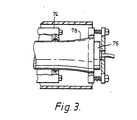
- Figure 3 illustrates a modified non-melt-contacting end for a probe of Figure 2.
- the end 78 of the core 54 is in the shape of an acoustic trumpet, with exponentially- curved side-walls; they accommodate on the end surface thereof a larger and more powerful piezoelectric crystal 76, for supplying larger amounts of energy to the melt.
- Each device illustrated in Figures 1, 2 and 3 is designed for use as a single probe, into a melt, both for transmission of ultrasound therein and reception of sound signals therefrom. It will of course be appreciated that in some circumstances it may be preferable to use two probes, one for transmission of signals into the melt and a second for reception of signals therefrom, each probe having its own piezoelectric crystal. In such cases, it is more important to provide the reflection signal receiving probe with the cooling means as described and defined herein, for maximum reception of reflected signals for analysis, but it is preferred that both probes should be so equipped and operated.
- Figure 4 of the accompanying drawings is a diagrammatic illustration of a block diagram for a pulse-echo ultrasonic testing technique for use with the probe as described herein. This is generally an arrangement according to the prior art, but useful in connection with the improved probe of the present invention.
- separate probes are designated, having respective transmitting crystals and receiving crystals, for the supplied ultrasound pulses and the received sound reflections.
- Figure 4 indicates the use of alternative arrangements, namely vertically-disposed probes testing or treating a melt in a ladle 79, and horizontally- disposed probes testing or treating a melt in a tundish 80, from which the melt is fed to a mould 81.
- the reflected signals as received are displayed on a cathode ray tube display, for suitable measurement and analysis of the impurities and inhomogeneities located within the melt.
- the oscillograph of reflected ultrasound signals so displayed typically shows one or more peaks of large amplitude at its right-hand side, derived from ultrasound reflections from the bottom of the melt-containing vessel, and a series of peaks of lesser amplitude to the left, derived from ultrasound reflections from inhomogeneities or suspended impurity particles in the melt.
- the horizontal axis of the oscillograph is a time scale, and indicates the time lapse between transmission and reflection reception of an ultrasound signal, so that those reflections which have travelled farthest, i.e. those from the bottom of the melt, appear to the right on the oscillograph.
- the degree of purity of the melt may be determined from the amplitude of the ultrasound reflections from the bottom of the melt vessel.
- the number of impurity particles is counted, by counting the number of signal reflections from a given area and depth of the melt. Signal reflections appear on the time base of the oscillograph, according to the depth of the particle responsible for the reflection. By computer counting and conversion, assuming the test area of the melt to be representative, the number of impurity particles present can thus be computed.
- a computer can be arranged to take readings and measurements of the reflected sound at given intervals of time, and, by suitable programming, to compare the signals received at different times. This enables an operator to tell whether the detected inhomogeneities are moving within the melt or whether they are stationary, at fixed positions therein. This can be of considerable importance, especially when a melt is being treated with high energy ultrasound in order to improve its characteristics.
- Computer analysis of the readings can then indicate, for example, whether impurities are being driven to the surface of the melt, whether cavities and voids therein are being filled and air bubbles driven to the surface of the melt, or whether particles are being caused to coalesce or are being more finely broken down.
- a difficulty commonly encountered in ultrasound testing and treatment of melts is the obtaining of sufficiently deep penetration of the ultrasound into the melt, both to obtain ultrasound reflections from the bottom and throughout the depth of the melt for analysis, and to effect ultrasound treatment of the melt throughout its volume.
- the most troublesome impurity particles in a ferrous melt are particles which are less dense than molten steel, such as silicates and oxides. Provided that the particles are large enough (e.g. 200 pm or above), they will float to the top of a ferrous melt for removal by, for example, skimming or bottom pouring.
- the present invention provides a method by which impurity particles in a ferrous or aluminium melt can be caused to coalesce to a size sufficiently large that they float to the melt surface, for removal therefrom, utilising long pulsed ultrasound.
- pulsed ultrasound is supplied to a metal melt through a side inlet into the vessel, e.g. substantially horizontally.
- a probe of the invention as described above.
- a bigger and more powerful piezoelectric crystal can be accommodated, e.g. of the type illustrated in Figure 3, for supplying greater amounts of pulsed ultrasound energy to the melt.
Landscapes
- Physics & Mathematics (AREA)
- Health & Medical Sciences (AREA)
- Life Sciences & Earth Sciences (AREA)
- Chemical & Material Sciences (AREA)
- Immunology (AREA)
- Biochemistry (AREA)
- General Health & Medical Sciences (AREA)
- General Physics & Mathematics (AREA)
- Analytical Chemistry (AREA)
- Pathology (AREA)
- Engineering & Computer Science (AREA)
- Acoustics & Sound (AREA)
- Food Science & Technology (AREA)
- Medicinal Chemistry (AREA)
- Investigating Or Analyzing Materials By The Use Of Ultrasonic Waves (AREA)
- Investigating And Analyzing Materials By Characteristic Methods (AREA)
- Manufacture And Refinement Of Metals (AREA)
- Physical Or Chemical Processes And Apparatus (AREA)
Claims (14)
dadurch gekennzeichnet, daß der Stabkühler befähigt ist, bei Verwendung des Stabes in Kontakt mit dem geschmolzenen Metall mit der Schmelzetemperatur durch eine geeignete Strömung eines durch den Kühler fließenden Kühlmittels im Stab einen steilen Temperaturgradienten, der mindestens 700° C äquivalent ist, über eine Länge von 50 mm vom Punkt des Schmelzenkontaktes an zu erzeugen, bezogen auf einen zylindrischen Stahlstab von 25 mm Durchmesser.
Priority Applications (1)
| Application Number | Priority Date | Filing Date | Title |
|---|---|---|---|
| AT85902585T ATE50064T1 (de) | 1984-05-17 | 1985-05-17 | Pruefen von fluessigen schmelzen und dazu geeignete sonden. |
Applications Claiming Priority (2)
| Application Number | Priority Date | Filing Date | Title |
|---|---|---|---|
| CA454623 | 1984-05-17 | ||
| CA000454623A CA1235476A (en) | 1984-05-17 | 1984-05-17 | Testing of liquid melts |
Related Child Applications (2)
| Application Number | Title | Priority Date | Filing Date |
|---|---|---|---|
| EP88105717A Division EP0300136A3 (de) | 1984-05-17 | 1985-05-17 | Behandlung von flüssigen Schmelzen |
| EP88105717.8 Division-Into | 1988-04-11 |
Publications (2)
| Publication Number | Publication Date |
|---|---|
| EP0185696A1 EP0185696A1 (de) | 1986-07-02 |
| EP0185696B1 true EP0185696B1 (de) | 1990-01-31 |
Family
ID=4127891
Family Applications (2)
| Application Number | Title | Priority Date | Filing Date |
|---|---|---|---|
| EP88105717A Withdrawn EP0300136A3 (de) | 1984-05-17 | 1985-05-17 | Behandlung von flüssigen Schmelzen |
| EP85902585A Expired - Lifetime EP0185696B1 (de) | 1984-05-17 | 1985-05-17 | Prüfen von flüssigen schmelzen und dazu geeignete sonden |
Family Applications Before (1)
| Application Number | Title | Priority Date | Filing Date |
|---|---|---|---|
| EP88105717A Withdrawn EP0300136A3 (de) | 1984-05-17 | 1985-05-17 | Behandlung von flüssigen Schmelzen |
Country Status (7)
| Country | Link |
|---|---|
| US (2) | US4770699A (de) |
| EP (2) | EP0300136A3 (de) |
| JP (2) | JP2655258B2 (de) |
| AU (1) | AU4298985A (de) |
| CA (1) | CA1235476A (de) |
| DE (1) | DE3575788D1 (de) |
| WO (1) | WO1985005449A1 (de) |
Families Citing this family (30)
| Publication number | Priority date | Publication date | Assignee | Title |
|---|---|---|---|---|
| GB9107803D0 (en) * | 1991-04-12 | 1991-05-29 | Thor Ceramics Ltd | Device and method for quality control |
| US5708209A (en) * | 1996-08-27 | 1998-01-13 | Aluminum Company Of America | Apparatus and method for ultrasonic particle detection in molten metal |
| US5951163A (en) * | 1996-10-16 | 1999-09-14 | National Research Council Of Canada | Ultrasonic sensors for on-line monitoring of castings and molding processes at elevated temperatures |
| US6065344A (en) * | 1998-10-20 | 2000-05-23 | General Electric Co. | Apparatus and methods for cooling an ultrasonic inspection transducer for turbine rotor wheel repair |
| US6345082B1 (en) * | 1999-06-03 | 2002-02-05 | Thomas A. Galioto | Fuel assembly mechanical flow restriction apparatus for detecting failure in situ of nuclear fuel rods in a fuel assembly during reactor shutdown |
| FR2796155B1 (fr) | 1999-07-09 | 2001-09-07 | Pechiney Rhenalu | Procede et dispositif ameliores de comptage des inclusions dans un bain de metal liquide par ultrasons |
| JP2002062282A (ja) * | 2000-08-17 | 2002-02-28 | Daikure Co Ltd | 溶融金属用容器の欠陥部を測定する方法及び装置 |
| KR100515412B1 (ko) * | 2003-01-22 | 2005-09-14 | 도요탄소 가부시키가이샤 | 용융염 전해장치 |
| DE10310114A1 (de) * | 2003-03-06 | 2004-09-16 | Robert Bosch Gmbh | Vorrichtung und Verfahren zur hydrostatischen Druckbestimmung in einem Hochdruckbehälter mittels Ultraschalllaufzeitmessung |
| US7509993B1 (en) | 2005-08-13 | 2009-03-31 | Wisconsin Alumni Research Foundation | Semi-solid forming of metal-matrix nanocomposites |
| US7682556B2 (en) * | 2005-08-16 | 2010-03-23 | Ut-Battelle Llc | Degassing of molten alloys with the assistance of ultrasonic vibration |
| DE102007027391B3 (de) * | 2007-06-11 | 2009-01-08 | Forschungszentrum Dresden - Rossendorf E.V. | Ultraschallsensor zur Messung von lokalen Strömungsgeschwindigkeiten in flüssigen Schmelzen |
| DE102007027392B3 (de) * | 2007-06-11 | 2009-01-15 | Forschungszentrum Dresden - Rossendorf E.V. | Verfahren zur Messung von lokalen Strömungsgeschwindigkeiten in flüssigen Schmelzen |
| ATE539823T1 (de) * | 2008-03-05 | 2012-01-15 | Southwire Co | Ultraschallsonde mit schutzschicht aus niobium |
| US8215173B2 (en) * | 2008-08-05 | 2012-07-10 | Roger Spencer | UT method of identifying a stuck joint |
| RU2393941C1 (ru) * | 2009-03-20 | 2010-07-10 | Олег Владимирович Анисимов | Способ гомогенизации расплавов путем циклических фазовых преобразований и устройство для его осуществления |
| US8652397B2 (en) | 2010-04-09 | 2014-02-18 | Southwire Company | Ultrasonic device with integrated gas delivery system |
| US8574336B2 (en) | 2010-04-09 | 2013-11-05 | Southwire Company | Ultrasonic degassing of molten metals |
| UA108402C2 (xx) | 2010-10-28 | 2015-04-27 | Безпровідний наконечник | |
| FR2971793B1 (fr) * | 2011-02-18 | 2017-12-22 | Alcan Rhenalu | Demi-produit en alliage d'aluminium a microporosite amelioree et procede de fabrication |
| US9061928B2 (en) | 2011-02-28 | 2015-06-23 | Corning Incorporated | Ultrasonic transducer assembly for applying ultrasonic acoustic energy to a glass melt |
| US9063059B2 (en) | 2011-05-10 | 2015-06-23 | Edison Welding Institute, Inc. | Three-dimensional matrix phased array spot weld inspection system |
| US9145597B2 (en) | 2013-02-22 | 2015-09-29 | Almex Usa Inc. | Simultaneous multi-mode gas activation degassing device for casting ultraclean high-purity metals and alloys |
| JP6674376B2 (ja) | 2013-11-18 | 2020-04-01 | サウスワイヤー・カンパニー・リミテッド・ライアビリティ・カンパニーSouthwire Company,Llc | 溶融金属の脱ガス用排気口付き超音波プローブ |
| EP3112856A1 (de) * | 2015-07-03 | 2017-01-04 | Kamstrup A/S | Trübungssensor auf basis von ultraschallmessungen |
| US10233515B1 (en) | 2015-08-14 | 2019-03-19 | Southwire Company, Llc | Metal treatment station for use with ultrasonic degassing system |
| AT521579B1 (de) * | 2018-08-24 | 2021-10-15 | Engel Austria Gmbh | Verfahren zum Erfassen von Inhomogenitäten in Schmelzen |
| JP2023038733A (ja) | 2021-09-07 | 2023-03-17 | 株式会社東芝 | 超音波プローブ及び超音波検査装置 |
| WO2024077218A1 (en) * | 2022-10-06 | 2024-04-11 | Government Of The United States Of America, As Represented By The Secretary Of Commerce | High-temperature and high-pressure speed of sound apparatus and measuring the speed of sound in a sample at high-temperature and high-pressure |
| FR3161280A1 (fr) | 2024-04-12 | 2025-10-17 | C-Tec Constellium Technology Center | Procédé de calibration d’un dispositif de mesure ultrasonore destinée à analyser un métal liquide. |
Family Cites Families (6)
| Publication number | Priority date | Publication date | Assignee | Title |
|---|---|---|---|---|
| GB1127231A (en) * | 1965-01-06 | 1968-09-18 | British Aluminium Co Ltd | Improvements in or relating to methods of and apparatus for testing molten metal |
| CH488183A (de) * | 1967-12-23 | 1970-03-31 | Knapsack Ag | Verfahren und Vorrichtung zur Ultraschall-Prüfung von Metallwänden |
| US4287755A (en) * | 1979-09-12 | 1981-09-08 | Reynolds Metals Company | Probes for the ultrasonic treatment or inspection of molten aluminum |
| US4261197A (en) * | 1979-09-12 | 1981-04-14 | Reynolds Metals Company | Probe for the ultrasonic inspection of molten aluminum |
| NO158107C (no) * | 1979-10-09 | 1988-07-13 | Showa Aluminium Co Ltd | Fremgangsmaate ved smelting av aluminium. |
| US4662215A (en) * | 1984-08-20 | 1987-05-05 | Aluminum Company Of America | Apparatus and method for ultrasonic detection of inclusions in a molten body |
-
1984
- 1984-05-17 CA CA000454623A patent/CA1235476A/en not_active Expired
-
1985
- 1985-05-17 AU AU42989/85A patent/AU4298985A/en not_active Abandoned
- 1985-05-17 WO PCT/GB1985/000212 patent/WO1985005449A1/en not_active Ceased
- 1985-05-17 EP EP88105717A patent/EP0300136A3/de not_active Withdrawn
- 1985-05-17 US US06/826,149 patent/US4770699A/en not_active Expired - Fee Related
- 1985-05-17 EP EP85902585A patent/EP0185696B1/de not_active Expired - Lifetime
- 1985-05-17 DE DE8585902585T patent/DE3575788D1/de not_active Expired - Lifetime
- 1985-05-17 JP JP60502157A patent/JP2655258B2/ja not_active Expired - Lifetime
-
1989
- 1989-08-10 US US07/393,060 patent/US4981045A/en not_active Expired - Lifetime
-
1994
- 1994-05-30 JP JP6152545A patent/JP2747458B2/ja not_active Expired - Fee Related
Non-Patent Citations (2)
| Title |
|---|
| Journal of the Unstitute of Metals, vol 88, 1959-1960, London (GB), pages 121-127, NDG Mountford et al: "Precipitation effects in liquid aluminium alloys. Experiments with a pulsed ultrasonic Technique", see page 121 and page 126 * |
| Soviet Journal of Nondestructive Testing, vol 15, nr 5, May 1979, New York (US) VM Lantukh et al: "Ultransonic inspection of a metal at high temperature", see pages 404 and 405 * |
Also Published As
| Publication number | Publication date |
|---|---|
| DE3575788D1 (de) | 1990-03-08 |
| EP0185696A1 (de) | 1986-07-02 |
| EP0300136A2 (de) | 1989-01-25 |
| WO1985005449A1 (en) | 1985-12-05 |
| JPS61502208A (ja) | 1986-10-02 |
| US4770699A (en) | 1988-09-13 |
| CA1235476A (en) | 1988-04-19 |
| JP2655258B2 (ja) | 1997-09-17 |
| EP0300136A3 (de) | 1990-05-16 |
| US4981045A (en) | 1991-01-01 |
| JPH08225860A (ja) | 1996-09-03 |
| AU4298985A (en) | 1985-12-13 |
| JP2747458B2 (ja) | 1998-05-06 |
Similar Documents
| Publication | Publication Date | Title |
|---|---|---|
| EP0185696B1 (de) | Prüfen von flüssigen schmelzen und dazu geeignete sonden | |
| CA2133823C (en) | Ultrasonic treatment of liquids in particular metal melts | |
| CA2429063C (en) | Apparatus and method for in situ, real time measurements of properties of liquids | |
| US4730493A (en) | Process and device for ultrasonic detection of gas bubbles in a liquid metal | |
| KR100424037B1 (ko) | 물질의 두께 측정 방법 | |
| EP0469044B1 (de) | Einschlusssensor für metallschmelzen zur kontinuierlichen verwendung | |
| AU647388B2 (en) | Single-use disposable molten metal inclusion sensor | |
| EP0035545B1 (de) | Sonden für die ultraschallbehandlung oder -prüfung geschmolzenen aluminiums | |
| EP0119770B1 (de) | Verfahren und Vorrichtung zur Feststellung und Messung von Teilchen in einem flüssigen Metall | |
| JP4865781B2 (ja) | 超音波測定方法及び装置 | |
| US5708209A (en) | Apparatus and method for ultrasonic particle detection in molten metal | |
| US4563895A (en) | Apparatus and method for ultrasonic detection of inclusions in molten metals | |
| EP0035563B1 (de) | Sonde für die ultraschallprüfung geschmolzenen aluminiums | |
| EP1354188B1 (de) | Vorrichtung zur erfassung und messung von teilchen in geschmolzenem metall | |
| EP0132296B1 (de) | Einrichtung zum Erfassen des Schlackenausflusses | |
| GB2255408A (en) | Ultrasonic melt probe with built-in reflector | |
| Ono et al. | An on-line ultrasonic cleanliness analyzer for molten light metals | |
| Gallo et al. | Ultrasound for On-Line Inclusion Detection in Molten Aluminum Alloys: Technology Assessment | |
| Ono et al. | Development of ultrasonic techniques with buffer rod in molten aluminum | |
| JPH07100833B2 (ja) | スカル溶融深度測定の装置および方法 | |
| Baharis et al. | Ultrasonic detection of heat fronts in continuously cast steel product | |
| Hauser | Ultra adhesives for ultrasonic bonding | |
| DE102004011553A1 (de) | Messvorrichtung und Messverfahren zur Zustandsbestimmung eines Metallschmelzenstroms |
Legal Events
| Date | Code | Title | Description |
|---|---|---|---|
| PUAI | Public reference made under article 153(3) epc to a published international application that has entered the european phase |
Free format text: ORIGINAL CODE: 0009012 |
|
| 17P | Request for examination filed |
Effective date: 19860205 |
|
| AK | Designated contracting states |
Kind code of ref document: A1 Designated state(s): AT BE CH DE FR GB IT LI LU NL SE |
|
| 17Q | First examination report despatched |
Effective date: 19871030 |
|
| GRAA | (expected) grant |
Free format text: ORIGINAL CODE: 0009210 |
|
| AK | Designated contracting states |
Kind code of ref document: B1 Designated state(s): AT BE CH DE FR GB IT LI LU NL SE |
|
| PG25 | Lapsed in a contracting state [announced via postgrant information from national office to epo] |
Ref country code: IT Free format text: LAPSE BECAUSE OF FAILURE TO SUBMIT A TRANSLATION OF THE DESCRIPTION OR TO PAY THE FEE WITHIN THE PRESCRIBED TIME-LIMIT;WARNING: LAPSES OF ITALIAN PATENTS WITH EFFECTIVE DATE BEFORE 2007 MAY HAVE OCCURRED AT ANY TIME BEFORE 2007. THE CORRECT EFFECTIVE DATE MAY BE DIFFERENT FROM THE ONE RECORDED. Effective date: 19900131 Ref country code: LI Effective date: 19900131 Ref country code: BE Effective date: 19900131 Ref country code: NL Effective date: 19900131 Ref country code: CH Effective date: 19900131 |
|
| REF | Corresponds to: |
Ref document number: 50064 Country of ref document: AT Date of ref document: 19900215 Kind code of ref document: T |
|
| ET | Fr: translation filed | ||
| RAP4 | Party data changed (patent owner data changed or rights of a patent transferred) |
Owner name: MOUNTFORD, NORMAN DUNCAN GERARD |
|
| REF | Corresponds to: |
Ref document number: 3575788 Country of ref document: DE Date of ref document: 19900308 |
|
| RAP4 | Party data changed (patent owner data changed or rights of a patent transferred) |
Owner name: MOUNTFORD, NORMAN DUNCAN GERARD |
|
| REG | Reference to a national code |
Ref country code: CH Ref legal event code: PL |
|
| PG25 | Lapsed in a contracting state [announced via postgrant information from national office to epo] |
Ref country code: LU Free format text: LAPSE BECAUSE OF NON-PAYMENT OF DUE FEES Effective date: 19900531 |
|
| NLV1 | Nl: lapsed or annulled due to failure to fulfill the requirements of art. 29p and 29m of the patents act | ||
| PLBE | No opposition filed within time limit |
Free format text: ORIGINAL CODE: 0009261 |
|
| STAA | Information on the status of an ep patent application or granted ep patent |
Free format text: STATUS: NO OPPOSITION FILED WITHIN TIME LIMIT |
|
| 26N | No opposition filed | ||
| EAL | Se: european patent in force in sweden |
Ref document number: 85902585.0 |
|
| REG | Reference to a national code |
Ref country code: GB Ref legal event code: 732E |
|
| REG | Reference to a national code |
Ref country code: FR Ref legal event code: TP |
|
| REG | Reference to a national code |
Ref country code: GB Ref legal event code: IF02 |
|
| PGFP | Annual fee paid to national office [announced via postgrant information from national office to epo] |
Ref country code: GB Payment date: 20030428 Year of fee payment: 19 |
|
| PGFP | Annual fee paid to national office [announced via postgrant information from national office to epo] |
Ref country code: SE Payment date: 20030505 Year of fee payment: 19 |
|
| PGFP | Annual fee paid to national office [announced via postgrant information from national office to epo] |
Ref country code: AT Payment date: 20030506 Year of fee payment: 19 |
|
| PGFP | Annual fee paid to national office [announced via postgrant information from national office to epo] |
Ref country code: FR Payment date: 20030512 Year of fee payment: 19 |
|
| PGFP | Annual fee paid to national office [announced via postgrant information from national office to epo] |
Ref country code: DE Payment date: 20030514 Year of fee payment: 19 |
|
| PG25 | Lapsed in a contracting state [announced via postgrant information from national office to epo] |
Ref country code: AT Free format text: LAPSE BECAUSE OF NON-PAYMENT OF DUE FEES Effective date: 20040517 Ref country code: GB Free format text: LAPSE BECAUSE OF NON-PAYMENT OF DUE FEES Effective date: 20040517 |
|
| PG25 | Lapsed in a contracting state [announced via postgrant information from national office to epo] |
Ref country code: SE Free format text: LAPSE BECAUSE OF NON-PAYMENT OF DUE FEES Effective date: 20040518 |
|
| PG25 | Lapsed in a contracting state [announced via postgrant information from national office to epo] |
Ref country code: DE Free format text: LAPSE BECAUSE OF NON-PAYMENT OF DUE FEES Effective date: 20041201 |
|
| EUG | Se: european patent has lapsed | ||
| GBPC | Gb: european patent ceased through non-payment of renewal fee |
Effective date: 20040517 |
|
| PG25 | Lapsed in a contracting state [announced via postgrant information from national office to epo] |
Ref country code: FR Free format text: LAPSE BECAUSE OF NON-PAYMENT OF DUE FEES Effective date: 20050131 |
|
| REG | Reference to a national code |
Ref country code: FR Ref legal event code: ST |