EP0185514B1 - Appareil pour la récupération de chaleur - Google Patents
Appareil pour la récupération de chaleur Download PDFInfo
- Publication number
- EP0185514B1 EP0185514B1 EP85309036A EP85309036A EP0185514B1 EP 0185514 B1 EP0185514 B1 EP 0185514B1 EP 85309036 A EP85309036 A EP 85309036A EP 85309036 A EP85309036 A EP 85309036A EP 0185514 B1 EP0185514 B1 EP 0185514B1
- Authority
- EP
- European Patent Office
- Prior art keywords
- exhaust gas
- heat
- radiation body
- furnace
- waste heat
- Prior art date
- Legal status (The legal status is an assumption and is not a legal conclusion. Google has not performed a legal analysis and makes no representation as to the accuracy of the status listed.)
- Expired
Links
- 239000002918 waste heat Substances 0.000 title claims description 27
- 238000011084 recovery Methods 0.000 title claims description 20
- 239000007789 gas Substances 0.000 claims description 53
- 230000005855 radiation Effects 0.000 claims description 52
- 238000005192 partition Methods 0.000 claims description 19
- 229910010293 ceramic material Inorganic materials 0.000 claims description 7
- 238000002485 combustion reaction Methods 0.000 claims description 4
- 239000000112 cooling gas Substances 0.000 description 5
- 239000000428 dust Substances 0.000 description 3
- 238000010438 heat treatment Methods 0.000 description 3
- 238000009825 accumulation Methods 0.000 description 1
- PNEYBMLMFCGWSK-UHFFFAOYSA-N aluminium oxide Inorganic materials [O-2].[O-2].[O-2].[Al+3].[Al+3] PNEYBMLMFCGWSK-UHFFFAOYSA-N 0.000 description 1
- 230000015572 biosynthetic process Effects 0.000 description 1
- 238000001816 cooling Methods 0.000 description 1
- -1 corderite Inorganic materials 0.000 description 1
- 230000003247 decreasing effect Effects 0.000 description 1
- KZHJGOXRZJKJNY-UHFFFAOYSA-N dioxosilane;oxo(oxoalumanyloxy)alumane Chemical compound O=[Si]=O.O=[Si]=O.O=[Al]O[Al]=O.O=[Al]O[Al]=O.O=[Al]O[Al]=O KZHJGOXRZJKJNY-UHFFFAOYSA-N 0.000 description 1
- 238000001035 drying Methods 0.000 description 1
- 230000008030 elimination Effects 0.000 description 1
- 238000003379 elimination reaction Methods 0.000 description 1
- 238000005516 engineering process Methods 0.000 description 1
- 239000000295 fuel oil Substances 0.000 description 1
- 238000012423 maintenance Methods 0.000 description 1
- 239000000203 mixture Substances 0.000 description 1
- 229910052863 mullite Inorganic materials 0.000 description 1
Images

Classifications
-
- F—MECHANICAL ENGINEERING; LIGHTING; HEATING; WEAPONS; BLASTING
- F24—HEATING; RANGES; VENTILATING
- F24H—FLUID HEATERS, e.g. WATER OR AIR HEATERS, HAVING HEAT-GENERATING MEANS, e.g. HEAT PUMPS, IN GENERAL
- F24H9/00—Details
-
- Y—GENERAL TAGGING OF NEW TECHNOLOGICAL DEVELOPMENTS; GENERAL TAGGING OF CROSS-SECTIONAL TECHNOLOGIES SPANNING OVER SEVERAL SECTIONS OF THE IPC; TECHNICAL SUBJECTS COVERED BY FORMER USPC CROSS-REFERENCE ART COLLECTIONS [XRACs] AND DIGESTS
- Y02—TECHNOLOGIES OR APPLICATIONS FOR MITIGATION OR ADAPTATION AGAINST CLIMATE CHANGE
- Y02P—CLIMATE CHANGE MITIGATION TECHNOLOGIES IN THE PRODUCTION OR PROCESSING OF GOODS
- Y02P80/00—Climate change mitigation technologies for sector-wide applications
- Y02P80/10—Efficient use of energy, e.g. using compressed air or pressurized fluid as energy carrier
- Y02P80/15—On-site combined power, heat or cool generation or distribution, e.g. combined heat and power [CHP] supply
-
- Y—GENERAL TAGGING OF NEW TECHNOLOGICAL DEVELOPMENTS; GENERAL TAGGING OF CROSS-SECTIONAL TECHNOLOGIES SPANNING OVER SEVERAL SECTIONS OF THE IPC; TECHNICAL SUBJECTS COVERED BY FORMER USPC CROSS-REFERENCE ART COLLECTIONS [XRACs] AND DIGESTS
- Y10—TECHNICAL SUBJECTS COVERED BY FORMER USPC
- Y10S—TECHNICAL SUBJECTS COVERED BY FORMER USPC CROSS-REFERENCE ART COLLECTIONS [XRACs] AND DIGESTS
- Y10S165/00—Heat exchange
- Y10S165/901—Heat savers
-
- Y—GENERAL TAGGING OF NEW TECHNOLOGICAL DEVELOPMENTS; GENERAL TAGGING OF CROSS-SECTIONAL TECHNOLOGIES SPANNING OVER SEVERAL SECTIONS OF THE IPC; TECHNICAL SUBJECTS COVERED BY FORMER USPC CROSS-REFERENCE ART COLLECTIONS [XRACs] AND DIGESTS
- Y10—TECHNICAL SUBJECTS COVERED BY FORMER USPC
- Y10S—TECHNICAL SUBJECTS COVERED BY FORMER USPC CROSS-REFERENCE ART COLLECTIONS [XRACs] AND DIGESTS
- Y10S165/00—Heat exchange
- Y10S165/904—Radiation
Definitions
- the present invention relates to a waste heat recovery apparatus for recovering the waste heat of exhaust gas discharged from a high temperature furnace, such as an industrial furnace (GB-A-931 111
- a heat exchanger so as to recover the waste heat of high temperature exhaust gas discharged from the furnace.
- the recovered waste heat is used, for example, to pre-heat fresh combustion air to be supplied to the furnace.
- the heat exchanger used for this purpose is generally provided with metallic radiation tubes having a limited heat resistivity.
- the exhaust gas temperature exceeds 800°C, for example, the gas cannot be supplied to the heat exchanger directly because of the insufficient heat resistivity of the metallic radiation tubes.
- the temperature of the exhaust gas discharged from the heat exchanger still remains as high as 500-600°C, even after the recovery of the waste heat by the heat exchanger.
- the heat recovery rate thus amounts to only 40-50%, so that an improvement in the overall thermal efficiency of the furnace can be achieved only in a limited range. This is due to the fact that a substantial part of the heat content of the exhaust gas is wasted in heating the added cooling gas, and cannot be recovered efficiently.
- the present invention contemplates the elimination or amelioration of the above-mentioned problems, by providing a novel and improved waste heat recovery apparatus which makes it possible to efficiently and economically recover waste heat directly from the exhaust gas at a temperature as high as 1,000°C or more.
- a waste heat recovery apparatus for recovering the waste heat of exhaust gas discharged from an exhaust gas outlet of a high-temperature furnace, characterized in that said apparatus comprises a radiation body which consists essentially of ceramic material, said radiation body having a heat radiation surface adapted to be arranged near said exhaust gas outlet and toward the inside of the furnace, and a plurality of preferably regularly arranged channels extending through the ceramic material from said heat radiation surface and allowing passage of the exhaust gas.
- Provision of the radiation body arranged nearthe exhaust gas outlet of the furnace makes it possible to primarily recover the heat of the exhaust gas, and to radiate the recovered heat directly into the inside of the furnace, so that the heat recovery rate can be improved considerably.
- the temperature of the exhaust gas passed through the radiation body has been lowered solely due to the primary heat recovery, so that a heat exchanger arranged on the downstream side of the radiation body need not be of expensive structure. Because additional cooling gas is not required to lower the temperature of the exhaust gas to be passed through the heat exchanger, the capacity of the exhaust gas post-treating equipment need not be increased.
- a high-temperature furnace designated generally by reference numeral 1, which may be a burning furnace, heating furnace, drying furnace, or the like, and to which the present invention is applied.
- the furnace 1 has a burner 2 for heating the chamber within the furnace 1, and is associated with a heat exchanger 3 for recovering the waste heat of the exhaust gas discharged from the furnace 1.
- the heat exchanger 3 is inserted into an exhaust gas duct 4 which serves to discharge exhaust gas from the furnace 1, and is arranged so that fresh combustion air supplied by a blower 5 under pressure is pre-heated by the recovered waste heat of the exhaust gas.
- the heat exchanger 3 is inserted also into a combustion air passage 6 with one end connected to the blower 5 and another end connected with the burner 2.
- various types of heat exchanger may be used, such as shell type, radiation tube type, honeycomb type, and the like.
- a novel waste heat recovery apparatus which is arranged in the vicinity of exhaust gas discharge opening 7 formed in a wall of the furnace 1, and on the inlet side of the heat exchanger 3.
- This apparatus has a number of regular channels 8 allowing passage of the exhaust gas therethrough, and consists essentially of ceramic material formed as a radiation body 9 with a heat radiation surface disposed toward the inside of the furnace 1.
- the radiation body 9 in the embodiment illustrated in Fig. 1 is arranged within the housing of the heat exchanger 3 and forms with the latter a unitary assembly.
- the radiation body 9 comprises a honeycomb structure of ceramic material, such as corderite, mullite, alumina or the like, with a plurality of partition walls 10 defining the channels 8.
- ceramic material such as corderite, mullite, alumina or the like
- partition walls 10 defining the channels 8.
- the radiation body 9 is heated by the exhaust gas and radiates substantial amount of heat from the heat radiation surface toward the inside of the furnace 1, thereby allowing a primary recovery of the waste heat of the exhaust gas.
- the arrangement of the partition walls 10 of the honeycomb structure, or the channels 8 defined by the partition walls 10, should be such that objects on one side of the radiation body 9 are not visible from another side of the radiation body 9 through the channels 8.
- the partition walls 10 of the radiation body 9 are inclined with respect to the longitudinal axis of the exhaust gas duct 4, which extends perpendicularly to the heat radiation surface of the radiation body 9, at an angle within a range of from 5° to 60°, preferably from 15° to 30°.
- the radiation body 9 consists of a plurality of layers of honeycomb structures, as shown in Fig. 2, these structures are preferably arranged such that the channels 8 or partition walls 10 of one layer are contiguous with the channels 8 or partition walls 10 of at least one neighbouring layer in a zig-zag fashion.
- the radiation body 9 consists of two or three layers of honeycomb structures, since provision of an excessive number of such layers results in an increased pressure drop of the exhaust gas.
- the honeycomb structure which may be suitably used in the present invention is typically featured by an equivalent channel diameter of 3 to 50 mm, a partition wall thickness of 1 to 10 mm, and an open frontal area of 30% or more. Also, the radiation body 9 has a typical overall thickness of 50 to 300 mm.
- the radiation body 9 when heated by the exhaust gas radiates heat not only toward the inside of the furnace 1, but also into the heat exchanger 3.
- the exhaust gas flow speed along the surface of the partition walls 10, which faces the inside of the furnace 1 becomes greater than that along the opposite surface of the partition walls 10.
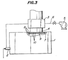
- Fig. 3 shows another embodiment of the present invention, wherein the same reference numerals used in Figs. 1 and 2 denote the same or functionally equivalent elements.
- the radiation body 9 is secured directly to the wall of the furnace 1 at a location corresponding to the exhaust gas discharge opening.
- Such an arrangement of the radiation body serves to improve the efficiency of the waste heat recovery by the radiation body, because the heat radiated from the radiation body 9 toward the inside of the furnace 1 is completely used to heat the furnace, and no part of the radiated heat is wasted to heat the exhaust gas duct 4.
- the apparatus of the present invention explained above has been used for waste heat recovery in a heavy oil burning furnace with the capacity of 1,000,000 kcal/H, and the data so obtained is shown in the following table.
- the total heat quantity radiated from the radiation body 9 into the inside of the furnace 1 amounts to 30% or more of the heat content of the exhaust gas.
- the heat of the exhaust gas which has passed through the radiation body 9 is further recovered by the heat exchanger 3 arranged on the downstream side of the radiation body 9 as shown in Fig. 1, so that the overall waste heat recovery efficiency of the furnace 1 can be improved up to about 60-70%.
- the radiation body 9 consists essentially of ceramic material, it can be used with a furnace whose inside is to be maintained at an extremely high temperature of 1,000 to 1,500°C. Formation of regular channels 8 in the radiation body 9 ensures that the pressure drop of the exhaust gas across the radiation body 9 can be minimized below 10 mm Aq or less, and thus the channels are prevented from getting clogged by the dust, and can be used for a long time without particular maintenance. Furthermore, the temperature of the exhaust gas passed through the radiation body 9 is decreased considerably, due to the primary waste heat recovery. This results in that the thermal load to which the heat exchanger is subjected can be reduced, and hence the heat exchanger need not be of expensive structure.
- the present invention thus provides a complete solution of various problems inherent to the conventional arrangement wherein waste heat recovery is solely effected by a heat exchanger.
Landscapes
- Engineering & Computer Science (AREA)
- Physics & Mathematics (AREA)
- Thermal Sciences (AREA)
- Chemical & Material Sciences (AREA)
- Combustion & Propulsion (AREA)
- Mechanical Engineering (AREA)
- General Engineering & Computer Science (AREA)
- Waste-Gas Treatment And Other Accessory Devices For Furnaces (AREA)
- Heat-Exchange Devices With Radiators And Conduit Assemblies (AREA)
Claims (8)
Applications Claiming Priority (2)
| Application Number | Priority Date | Filing Date | Title |
|---|---|---|---|
| JP191013/84U | 1984-12-17 | ||
| JP1984191013U JPS61106900U (fr) | 1984-12-17 | 1984-12-17 |
Publications (3)
| Publication Number | Publication Date |
|---|---|
| EP0185514A2 EP0185514A2 (fr) | 1986-06-25 |
| EP0185514A3 EP0185514A3 (en) | 1986-08-13 |
| EP0185514B1 true EP0185514B1 (fr) | 1988-03-16 |
Family
ID=16267423
Family Applications (1)
| Application Number | Title | Priority Date | Filing Date |
|---|---|---|---|
| EP85309036A Expired EP0185514B1 (fr) | 1984-12-17 | 1985-12-12 | Appareil pour la récupération de chaleur |
Country Status (4)
| Country | Link |
|---|---|
| US (1) | US4651814A (fr) |
| EP (1) | EP0185514B1 (fr) |
| JP (1) | JPS61106900U (fr) |
| DE (1) | DE3561908D1 (fr) |
Families Citing this family (13)
| Publication number | Priority date | Publication date | Assignee | Title |
|---|---|---|---|---|
| US4735531A (en) * | 1987-09-17 | 1988-04-05 | L & D Sales, Inc. | Acoustic tile cutting assembly |
| DE3836843A1 (de) * | 1987-11-03 | 1989-05-18 | Vaillant Joh Gmbh & Co | Brennerbeheiztes geraet, insbesondere wasserheizer |
| EP0580806B1 (fr) * | 1991-04-15 | 1998-02-25 | The Scientific Ecology Group, Inc. | Echangeur de chaleur a tres haute temperature |
| DE19814585A1 (de) * | 1997-08-22 | 1999-02-25 | Ford Global Tech Inc | Abgassystem |
| KR101255691B1 (ko) * | 2004-07-29 | 2013-04-17 | 퀄컴 엠이엠에스 테크놀로지스, 인크. | 간섭 변조기의 미소기전 동작을 위한 시스템 및 방법 |
| US8350444B2 (en) | 2009-05-14 | 2013-01-08 | The Neothermal Energy Company | Method and apparatus for conversion of heat to electrical energy using polarizable materials and an internally generated poling field |
| US8946538B2 (en) | 2009-05-14 | 2015-02-03 | The Neothermal Energy Company | Method and apparatus for generating electricity by thermally cycling an electrically polarizable material using heat from condensers |
| US9166139B2 (en) | 2009-05-14 | 2015-10-20 | The Neothermal Energy Company | Method for thermally cycling an object including a polarizable material |
| US9000651B2 (en) | 2009-05-14 | 2015-04-07 | The Neothermal Energy Company | Method and apparatus for generating electricity by thermally cycling an electrically polarizable material using heat from various sources and a vehicle comprising the apparatus |
| US8344585B2 (en) | 2009-05-14 | 2013-01-01 | The Neothermal Energy Company | Method and apparatus for conversion of heat to electrical energy using a new thermodynamic cycle |
| JP5775746B2 (ja) * | 2011-05-26 | 2015-09-09 | 株式会社超高温材料研究センター | 熱処理炉の熱効率改善方法 |
| JP6240371B2 (ja) * | 2011-09-05 | 2017-11-29 | 株式会社Ihi | 加熱炉および連続加熱炉 |
| US20130078047A1 (en) * | 2011-09-23 | 2013-03-28 | Bor-Yann Chuang | Fast changeable worktable of a carving machine |
Family Cites Families (16)
| Publication number | Priority date | Publication date | Assignee | Title |
|---|---|---|---|---|
| US3174228A (en) * | 1965-03-23 | Automatic heater control for a paper drying system | ||
| CA691329A (en) * | 1964-07-28 | Mills Lloyd | Radiant panel heating system | |
| US1603631A (en) * | 1923-03-28 | 1926-10-19 | Munhollon Frank | Heat-conserving system |
| US1748136A (en) * | 1925-09-03 | 1930-02-25 | Lipsius Samuel | Heating and drying apparatus |
| US1677136A (en) * | 1926-02-15 | 1928-07-17 | Surface Comb Company | Continuous carbonizing furnace |
| US2441594A (en) * | 1944-01-12 | 1948-05-18 | Brassert & Co | Apparatus for beneficiating nonmagnetic ores to render them magnetic |
| US2789521A (en) * | 1955-10-31 | 1957-04-23 | Edward J Wasp | Fluid heaters |
| GB931111A (en) * | 1960-02-08 | 1963-07-10 | Brown Fintube Co | Improvements in and relating to heat exchange recuperator units |
| US3130562A (en) * | 1960-11-02 | 1964-04-28 | Gen Electric | Cryogenic pumping apparatus |
| FR1377542A (fr) * | 1963-09-26 | 1964-11-06 | Procédé d'amélioration d'échanges thermiques | |
| US3175373A (en) * | 1963-12-13 | 1965-03-30 | Aero Vac Corp | Combination trap and baffle for high vacuum systems |
| US3360949A (en) * | 1965-09-20 | 1968-01-02 | Air Reduction | Cryopumping configuration |
| US3564648A (en) * | 1969-04-08 | 1971-02-23 | Borden Inc | Shucking of bivalves |
| JPS5147131A (ja) * | 1974-10-21 | 1976-04-22 | Toyoda Automatic Loom Works | Kyuchakukanenbosekihoho |
| JPS57187590A (en) * | 1981-05-13 | 1982-11-18 | Daido Steel Co Ltd | Heat exchange method |
| JPS59209846A (ja) * | 1983-05-13 | 1984-11-28 | 技術研究組合工業炉技術研究所 | 通気性固体 |
-
1984
- 1984-12-17 JP JP1984191013U patent/JPS61106900U/ja active Pending
-
1985
- 1985-12-06 US US06/805,798 patent/US4651814A/en not_active Expired - Lifetime
- 1985-12-12 EP EP85309036A patent/EP0185514B1/fr not_active Expired
- 1985-12-12 DE DE8585309036T patent/DE3561908D1/de not_active Expired
Also Published As
| Publication number | Publication date |
|---|---|
| EP0185514A2 (fr) | 1986-06-25 |
| JPS61106900U (fr) | 1986-07-07 |
| US4651814A (en) | 1987-03-24 |
| DE3561908D1 (en) | 1988-04-21 |
| EP0185514A3 (en) | 1986-08-13 |
Similar Documents
| Publication | Publication Date | Title |
|---|---|---|
| EP0185514B1 (fr) | Appareil pour la récupération de chaleur | |
| EP1751486B1 (fr) | Echangeur thermique | |
| EP0071073B1 (fr) | Tube radiant | |
| GB2076134A (en) | Combustion air preheater | |
| GB2075360A (en) | Water-cooled fluidised bed distributor plate | |
| US4069008A (en) | Method and apparatus for heating a workpiece | |
| EP0068360B1 (fr) | Utilisation d'un objet céramique poreux comme isolateur thermique perméable au gaz | |
| US4751910A (en) | Flue gas/combustion air heat exchanger | |
| US4165716A (en) | Process air coolers used for combustion air preheating | |
| GB2058326A (en) | Recuperator | |
| US3233664A (en) | Recuperator for flue gases containing sinterable dusts | |
| JPS6021385Y2 (ja) | 輻射管付き加熱炉 | |
| US2641456A (en) | Heat recovery apparatus | |
| JPS59113117A (ja) | 連続式加熱炉 | |
| JPH07171440A (ja) | サイクロン式集塵装置 | |
| SU853300A1 (ru) | Воздухоподогреватель | |
| CN2266719Y (zh) | 螺旋板式热风炉 | |
| CN111981680B (zh) | 燃生物质水锅炉 | |
| KR102337850B1 (ko) | 응축열교환기가 구비된 보일러 | |
| SU1196657A1 (ru) | Футеровка печи с внутренней рекуперацией тепла | |
| JPS6133437Y2 (fr) | ||
| SU1186660A1 (ru) | Печь с внутренней рекуперацией тепла | |
| SU1191717A1 (ru) | Печь дл термической обработки сыпучего материала | |
| JP3038338B2 (ja) | 竪型焼成炉 | |
| SU1368338A1 (ru) | Рекуперативный нагревательный колодец |
Legal Events
| Date | Code | Title | Description |
|---|---|---|---|
| PUAI | Public reference made under article 153(3) epc to a published international application that has entered the european phase |
Free format text: ORIGINAL CODE: 0009012 |
|
| AK | Designated contracting states |
Kind code of ref document: A2 Designated state(s): BE DE FR GB SE |
|
| PUAL | Search report despatched |
Free format text: ORIGINAL CODE: 0009013 |
|
| AK | Designated contracting states |
Kind code of ref document: A3 Designated state(s): BE DE FR GB SE |
|
| 17P | Request for examination filed |
Effective date: 19861002 |
|
| 17Q | First examination report despatched |
Effective date: 19870522 |
|
| GRAA | (expected) grant |
Free format text: ORIGINAL CODE: 0009210 |
|
| AK | Designated contracting states |
Kind code of ref document: B1 Designated state(s): BE DE FR GB SE |
|
| REF | Corresponds to: |
Ref document number: 3561908 Country of ref document: DE Date of ref document: 19880421 |
|
| ET | Fr: translation filed | ||
| PLBE | No opposition filed within time limit |
Free format text: ORIGINAL CODE: 0009261 |
|
| STAA | Information on the status of an ep patent application or granted ep patent |
Free format text: STATUS: NO OPPOSITION FILED WITHIN TIME LIMIT |
|
| 26N | No opposition filed | ||
| PGFP | Annual fee paid to national office [announced via postgrant information from national office to epo] |
Ref country code: GB Payment date: 19901130 Year of fee payment: 6 |
|
| PGFP | Annual fee paid to national office [announced via postgrant information from national office to epo] |
Ref country code: FR Payment date: 19901214 Year of fee payment: 6 |
|
| PGFP | Annual fee paid to national office [announced via postgrant information from national office to epo] |
Ref country code: DE Payment date: 19901218 Year of fee payment: 6 |
|
| PGFP | Annual fee paid to national office [announced via postgrant information from national office to epo] |
Ref country code: SE Payment date: 19901219 Year of fee payment: 6 Ref country code: BE Payment date: 19901219 Year of fee payment: 6 |
|
| PG25 | Lapsed in a contracting state [announced via postgrant information from national office to epo] |
Ref country code: GB Effective date: 19911212 |
|
| PG25 | Lapsed in a contracting state [announced via postgrant information from national office to epo] |
Ref country code: SE Effective date: 19911213 |
|
| PG25 | Lapsed in a contracting state [announced via postgrant information from national office to epo] |
Ref country code: BE Effective date: 19911231 |
|
| BERE | Be: lapsed |
Owner name: NGK INSULATORS LTD Effective date: 19911231 |
|
| GBPC | Gb: european patent ceased through non-payment of renewal fee | ||
| PG25 | Lapsed in a contracting state [announced via postgrant information from national office to epo] |
Ref country code: FR Effective date: 19920831 |
|
| PG25 | Lapsed in a contracting state [announced via postgrant information from national office to epo] |
Ref country code: DE Effective date: 19920901 |
|
| REG | Reference to a national code |
Ref country code: FR Ref legal event code: ST |
|
| EUG | Se: european patent has lapsed |
Ref document number: 85309036.3 Effective date: 19920704 |